Fringe Rotary Transformer Replication Experiments

  • 189 Views
  • Last Post 2 weeks ago
FringeIdeas posted this 2 weeks ago

Hey! I was hesitating starting this thread because I already have too many experiments/replications in progress. But I couldn't help myself!

For a while now the RT idea has been something I wanted to mess around with, so I've been keeping my eyes open for a nice universal motor. And I found one last week. Brand new, some German model, I believe for washing machines. The guy had got it and just never used it. Brand new, I got it for 50 euros. Not bad.


Sorry, I scratched up the label a bit. I went ahead and took a band saw and cut off some of the supports that were on it so it would sit a little more flat on the desk.

I also opened it up. The two stator windings were in series, with the center tap. Which I thought was strange because assuming that center tap was used as one polarity then the stator windings were wound so they would be opposing each other. I went ahead and separated the center tap so each coil had it's own separate connection pin. But I'm hoping that if the stator windings were really meant to oppose each other, that the armature windings and brushes are not configured to fire at some strange angle.


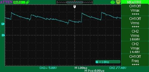
It starts up quite nice when DC is applied to the commutator pins. But the output voltage seems super low. If I run it at around 25 V input it will get up over 4000 rpm. Using one coil as output with a diode, It will take about 3-4 seconds to charge a capacitor just over 10 V. I'm not sure if that is expected, or if it should be quicker. When I have just a bulb connected, the voltage stays down around 2 V. It's a slim to nothing output.

Chris's experiments with this, in a 4 part video series..


Watching those, I think I should expect to see a horribly low output from the coils, until the proper bucking is achieved. 

So, I did start gathering parts and playing around with the circuit that Chris put out not too long ago, here on the thread The Rotary Transformer - Tinman

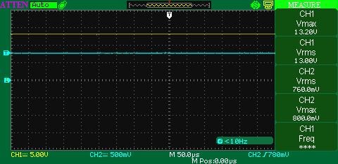
I have to locate an IRF-540. I'm using a IRF-640 in this picture and even though Rds(on) should be the same, 10V, the gate seems to want to start opening at around 4-5 V. I did add a pull-down resistor on the gate so it shouldn't be floating. Maybe I'm doing something else wrong.

I am thinking though, maybe I should shelf this for a bit and return to the Floyd Sweet style POC layout experiments, and the spark gap experiments. I now have the house to myself for a few days, and I was actually starting to make some progress with the other experiments. I will return to this soon though. Seems like a great alternative view on the same technology, and maybe there is something else to learn here.

Thanks,

Marcel

Order By: Standard | Newest | Votes
Chris posted this 2 weeks ago

Hey Marcel,

Thanks for Sharing! Awesome!

You know, the Circuit I posted, its as close to the description that was given by Tinman, as was possible, at the time, but I want to say, I think there was more to this. I don't believe there was any truth told about this.

Notable facts:

  • Internal Diode in the IRF540N is going to present a conductive path back in the opposite direction - Inductive.
  • The Fet Gate Terminals were across the Capacitor which was pretty flat at 10.4 volts, the Fett turn on voltage - Always on Fett?
  • Adding Capacitance changed the Machines operation, this is an important fact!
  • The speed of the rotor had to be optimized or the Generation of energy was reduced.
  • The trigger, of the Fett, gave a R x C Time constant, the Spike changed!
  • and more


There is enough here, to show, that the lucky hit that Tinman had, was completely misunderstood, he is unable to replicate any of what he achieved, because he did not take the time to fully understand what was occurring, and as a result, the RT was a one off fluke.


Before the RT, Tinman never ever showed, Bucking Coil Arrangement like I was showing.

Its a real shame, we could have had this 10 years ago, a small group of trolls, I have all their names, successfully stopped this, even though I was giving more info on it.

The Simple Facts we know, and simple experiments, we can make steps to replicate the RT, this will, however be difficult, because the Frequency of Operation is very hard to adjust, the Duty Cycle is very hard to adjust:


Please Note: I have modified the above Image for illustration purposes.

Where:

  • Red = TOn
  • Blue = Peak
  • Yellow = TOff


Please keep this statement in mind: "What if there was no Shorting, and instead Tinman was using the Fet for another reason"


A tiny DC Pulse into the Bucking Coil, you can see, the exact same effects are seen in the above video.


Both Coils are Inductively coupled, we bump the Voltage up ( Duty Cycle that is between the yellow lines I added, the R x C Time Constant changes ), the Diode is used, we use the Sawtooth Waveform to Pump Current, to Charge the Cap again and power the Load. In the above image, note the flip in polarity, TOn is on the Negative side of the Zero Graticule Line ( Marked by the number 2 in the image ), as you point out, turning on at around 4-5 volts, then flips from Negative to Positive, a Coil can NOT just Flip Polarity like that unless it is forced to. It really is worth thinking about this polarity flip in detail!

Here is a guess, which needs more work:


L1 flips polarity after Q1 turns off at TOff. Q1 Conducts reverse, through the internal diode. Don't forget, we need opposing Magnetic Fields for the Sawtooth Wave to be present, we learned this in prior experiments!

Note: This is a guess, but remember a full capacitor cannot be charged any more than it already is for a given Voltage. The capacitor must be emptied some.

I am trying to encourage the incorporation of Feed Forwards and Feed Backs, if you cant already tell.

Best Wishes,

   Chris

FringeIdeas posted this 2 weeks ago

Hey Chris

Sorry I've been pretty busy this week, but I started vacation last evening. So time to play catch up and get myself back to the bench.

Thank you for the tips, good stuff. I was thinking something along the same lines as you have suggested, though I was tripping over my mosfet getting stuck at around 5 V. You gave me a few ideas to try. Though I think tomorrow I'm planning on playing around with the large POC setup as you have been showing lately. Maybe this weekend I'll get back to this setup and try a few variations of the circuit, and cap values.

Thank you again!

Marcel

  • Liked by
  • Chris
  • Plasmonic
We're Light Years Ahead!
Members Online:

No one online at the moment


Past Visitors: 0 | Live Visitors: 0


3D globe widget by: Chris Sykes

What is a Scalar:

In physics, scalars are physical quantities that are unaffected by changes to a vector space basis. Scalars are often accompanied by units of measurement, as in "10 cm". Examples of scalar quantities are mass, distance, charge, volume, time, speed, and the magnitude of physical vectors in general.

You need to forget the Non-Sense that some spout with out knowing the actual Definition of the word Scalar! Some people talk absolute Bull Sh*t!

The pressure P in the formula P = pgh, pgh is a scalar that tells you the amount of this squashing force per unit area in a fluid.

A Scalar, having both direction and magnitude, can be anything! The Magnetic Field, a Charge moving, yet some Numb Nuts think it means Magic Science!

Message from God:

Hello my children. This is Yahweh, the one true Lord. You have found creation's secret. Now share it peacefully with the world.

Ref: Message from God written inside the Human Genome

God be in my head, and in my thinking.

God be in my eyes, and in my looking.

God be in my mouth, and in my speaking.

Oh, God be in my heart, and in my understanding.

We love and trust in our Lord, Jesus Christ of Nazareth!

Your Support:

More than anything else, your contributions to this forum are most important! We are trying to actively get all visitors involved, but we do only have a few main contributors, which are very much appreciated! If you would like to see more pages with more detailed experiments and answers, perhaps a contribution of another type maybe possible:

PayPal De-Platformed me!

They REFUSE to tell me why!

We now use Wise!

Donate
Use E-Mail: Chris at aboveunity.com

The content I am sharing is not only unique, but is changing the world as we know it! Please Support Us!

Thank You So Much!

Weeks High Earners:
The great Nikola Tesla:
N. Tesla

Ere many generations pass, our machinery will be driven by a power obtainable at any point of the universe. This idea is not novel. Men have been led to it long ago by instinct or reason. It has been expressed in many ways, and in many places, in the history of old and new. We find it in the delightful myth of Antheus, who drives power from the earth; we find it among the subtle speculations of one of your splendid mathematicians, and in many hints and statements of thinkers of the present time. Throughout space there is energy. Is this energy static or kinetic? If static, our hopes are in vain; if kinetic - and this we know it is for certain - then it is a mere question of time when men will succeed in attaching their machinery to the very wheelwork of nature.

Experiments With Alternate Currents Of High Potential And High Frequency (February 1892).

Close