today i did a replication of the reactive power 'effect' which is described in the video above.
this is how it looks on the bench.
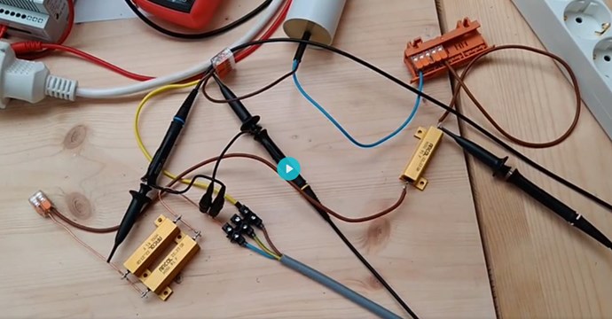
the energy comes from grid (isolation transformer / AC 50Hz 230V) - this is the gray cable on bottom.
brown is hot wire (phase), blue is neutral. the voltage is monitored on CH1 (yellow). oszilloscope ground is neutral.
the phase is connected to one side of capacitor (50uF) and the other side of capacitor goes to the load (0.1Ohm resistor, 50W). the voltage that is dissipating on the load is monitored by CH3 (pink).
i have CH2 (blue) to check the current which travels through the circuit. the voltage drop on the SHUNT (2x 0.1Ohm, 50W in parallel) is used to do some math on the oscilloscope.
not lets have a look at the situation on the load.
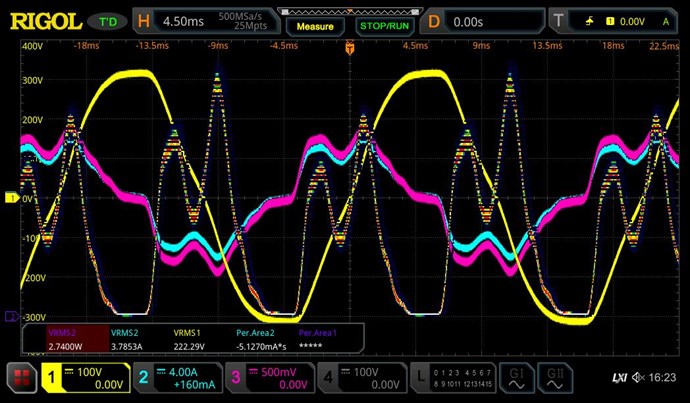
i have 2 MATH-functions on my scope and i use MATH2 for monitoring the power dissipation on load. voltage (CH3) and current (CH2) multiplied by scope-function (RMS value) - we can see 2,7W happening.
now we should have a look at the net-consumption.
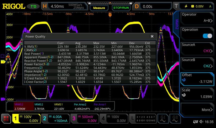
we can see a Phase angle of 90,xx° (this is important to have!)
the scope can calculate the Real Power based on voltage, current and phase angle.
have a nice day!


