My Friends,
@Jagau, I hope you dont mind, I just want to clear any possible confusion in others understandings.
For some, it may not be clear, and I think we need to make this clear; Electromagnetic Waves behave differently under many different circumstances!
Standing Waves in a single Coaxial Cable
This is a great video to see Standing Waves:
As it stands, there can be no Excess Energy "Generated" in this configuration! It is a Single Wire Wave.
In a Single Wire, a Coaxial Cable, there will be Nodes and Troughs, where there will be Current Nodes with no Voltage, and Voltage Nodes with No Current, the Standing Wave will be entirely Reactive.
Resonance frequencies may be maintained quite constant at high power levels so long as the load remains constant. We are all familiar with AM and FM propagation, where in the case as AM, the voltage amplitude varies, and with FM, the frequency is modulated. However, the output power sees a constant load impedance, that of the matched antenna system. If this changes, the input to the antenna is mismatched, and standing waves are generated resulting in a loss of power. The frequency is a forced response and remains constant. Power is lost and efficiency becomes less and less, depending on the degree of mismatch.
Ref: Floyd Sweet Magnetic Resonance
All Electromagnetic Waves must have a Source, E.G: An Antenna, or a Coil.
Electromagnetic Waves have two quantities:
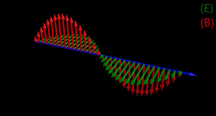
The Magnetic B is at 90 Degrees in Vector Space, to the Electric E! In viewing the Voltage, there can be a Phase Angle that also must be taken into account, normally around 90 degrees, but on the same plane as Current.
To create a Standing wave, we need two waves, each travelling in opposite directions:
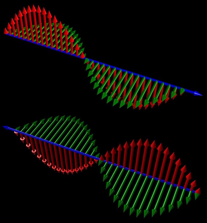
But, in the same Vector Space:
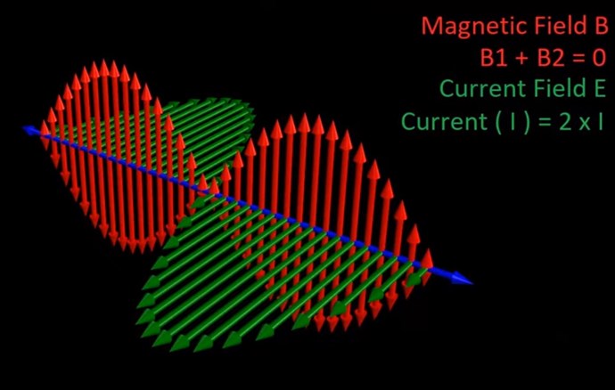
You can see, Electromagnetic Wave Mixing, in the same Vector Space has created a Current Standing Wave, but the Magnetic Field Component has canceled.
This is specifically in a Configuration where we have Two Sources, one for each Electromagnetic Wave! This is Superposition, and Floyd Sweet gave us some insight on this:
FIELD SUPER-POSITION AND THE VACUUM TRIODE
Electromagnetic induction with no measurable magnetic field is not new. It is well known that in the space surrounding a properly wound toroidal coil there is no magnetic field. This is due to the superposition of the fields. However, when alternating current is surging through a transformer an electric field surrounds it. When we apply the principle of superposition to the vacuum triode it becomes more obvious how the device is in fact operating.
The principle of superposition states that; "In order to calculate the resultant intensity of superimposed fields, each field must be dealt with individually as though the other were not present". The resultant is obtained by vector addition of each field considered singularly.
Consider for a moment the construction of the triode which includes the bifilar coils located within the fields of the two conditioned magnets.
When the current in one half of the conductors in the coils (i.e., one of the bifilar elements in each coil) of the device is moving up, both the current and the magnetic field follow the right-hand rule.
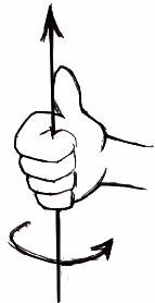
The resultant motional E-field would be vertical to both and inwardly directed.
At the same time the current in the other half of the conductors in the coils is moving down and both the current and magnetic field follow the right-hand rule.
The resulting motional E-field is again vertical to both and inwardly directed.
Thus, the resultant field intensity is double the intensity attributable to either one of the set of coil conductors taken singularly.
Expressed mathematically: E = ( B x V ) + ( -B x -V ) = 2 ( B x V )
Ref: Floyd Sweet - Nothing is Something
Wave mixing would normally require multiple Sources, especially to make for Energy Gains, for example, Andrey Melnichenko used two different Coils, each Coil having its own Electromagnetic Wave:
YouTube has Censored: Akula Vids!
NOTE: YouTube has Censored: Akula Vids! No results if one searches for Akula Vids on YouTube!

Sad isn't it!
One Coil was a multiple of the length of the other, as described by Andrey Melnichenko, normally around 2x the length.
Andrey Melnichenko stated:
Such experiments have repeatedly staged by the author. The question of why the power at the receiver antenna increases to 9, but not three times in three transmitting antennas? The fact that the receiving antenna is three times the induced emf increases, while the power is proportional to the square of the voltage. P = E2 / RH, where E - EDS, RH - the load resistance. Therefore, the power at the receiver antenna increases to nine times, not three times, as you might think. The usual classical interference is a multi-phase - in different regions of space electromagnetic waves are formed in different phases, where some are added, subtracted somewhere. Overall, therefore, these two effects cancel each other and the energy increment is not happening.
However, there is the so-called common-mode interference, in which occur only addition (in-phase) amplitudes of electromagnetic waves in the load. In this case the load generated by the additional energy in the form of heat or electricity.
Ref: Transgeneratsiya
One must take into account, the Action, Reaction Pairs in Wave Propagation. This is known as Wave destructive and constructive Interference.
"Generating" Signal Amplitude from Source to Destination, requires what?
So, there is a confusing, inside out meaning to these terms: destructive and constructive! It depends entirely, from which point of view, one takes, under a specific configuration!
Electromagnetic Wave Source
The Source of each of the Electromagnetic Wave, in Each Antenna, or each Coil, is simply, Electromagnetic Induction!
As one Coil has a Changing Magnetic Field, the other has a Voltage Induced! This is also true, back the other way around!
Magnetic Resonance is when Each Coils Amplitude is approximately Equal but Opposite in Magnetic Vector Direction!
I have not found a way, to have 2E and 2B at the same time. In other words, a I know of no way to achieve a Standing wave of B and E at the same time!
Floyd Sweet told us of such:
If the directions of the two signals are such that opposite H-fields cancel and E-fields add, an apparently steady E-field will be created. The energy density of the fields remain as calculated above, but the value of the E-field will double from E / 2 to E.
...
Similarly, if two signals flow through each other in such a way as to give the appearance of a steady magnetic field as a result of their E-field cancelling it is easily shown using the above equations to cancel out H and c...
Basically, he is saying one or the other, but B or E must Cancel.
Best Wishes,
Chris


