Natures Energy Pump, The Standing Wave

  • 132 Views
  • Last Post 16 hours ago
Chris posted this yesterday

My Friends,

Floyd Sweet used the Term "Team Wave" when describing his objective:

If the directions of the two signals are such that opposite H-fields cancel and E-fields add, an apparently steady E-field will be created. The energy density of the fields remain as calculated above, but the value of the E-field will double from E/2 to E. It is a simple matter using the equations E/H = √με and C = 1/√με for a team wave to get rid of H and C and so convert the first equation into the well known equation for energy density in the so-called electrostatic field: 


Because AI seems to be so popular as of late, lets start by asking Grok a question:

Grok, how does a Standing Wave pump Energy, for example in an electric Generator?


The Answer:


A standing wave in the context of an electric generator doesn't directly "pump" energy but rather describes a pattern of oscillation where energy is stored and oscillates in a fixed spatial configuration. To clarify how this relates to energy generation, let’s break it down:


Standing Waves in General


A standing wave forms when two waves of the same frequency and amplitude travel in opposite directions and interfere, creating fixed points of zero displacement (nodes) and maximum displacement (antinodes). In mechanical or electrical systems, standing waves can store energy in the form of potential and kinetic energy oscillating between these points.


Application in Electric Generators


In an electric generator, energy conversion typically involves mechanical motion (e.g., a rotating turbine) inducing an electromotive force (EMF) in a conductor via electromagnetic induction (Faraday’s Law). While standing waves are not a primary mechanism in most conventional generators, they can appear in specific contexts, such as resonant systems or specialized designs like magnetohydrodynamic (MHD) generators or resonant electromagnetic systems.


Here’s how standing waves might relate to energy transfer:

  1. Resonant Systems in Generators:

    • In some advanced generator designs, standing waves (mechanical or electromagnetic) can be used to enhance efficiency by operating at resonance. For example, in a resonant circuit within a generator, an oscillating electromagnetic field can form a standing wave pattern in a cavity or coil.

    • At resonance, the system maximizes energy transfer between magnetic and electric fields (in an LC circuit, for instance), reducing energy losses. The standing wave ensures that the energy oscillates efficiently between stored forms (e.g., magnetic field in the inductor and electric field in the capacitor).

    • This resonant condition can "pump" energy in the sense that it amplifies the oscillating current or voltage, which can then be converted to usable electrical power.


  2. Mechanical Standing Waves:

    • In certain experimental setups, standing mechanical waves (e.g., in a vibrating string, membrane, or fluid) can drive a generator. For instance, a standing wave in a piezoelectric material can generate electrical energy as the material deforms at antinodes, converting mechanical vibrations into electrical output.

    • The energy "pumped" here comes from the external source maintaining the standing wave (e.g., a mechanical driver or fluid flow), with the wave focusing energy at specific points for efficient conversion.


  3. Magnetohydrodynamic (MHD) Generators:

    • In MHD generators, a conductive fluid (like plasma) flows through a magnetic field, inducing current. Standing waves in the fluid or electromagnetic field can theoretically be used to optimize energy transfer by creating stable patterns of current flow, though this is rare in practical designs.

    • Here, the standing wave could help concentrate energy in specific regions, improving the efficiency of EMF induction.

Energy Flow in Standing Waves

  • The energy in a standing wave is not transported along the medium (as in a traveling wave) but oscillates between kinetic and potential forms at the antinodes. For a generator, this stored energy can be tapped by coupling the system to an external circuit or load.

  • For example, in a resonant cavity generator, the standing electromagnetic wave’s energy is periodically transferred to an external circuit via inductive or capacitive coupling, effectively "pumping" energy into the electrical output.


Practical Example

Consider a Tesla coil or a resonant transformer, where a standing electromagnetic wave in the coil maximizes voltage at specific points. The energy stored in the oscillating electric and magnetic fields is transferred to a load (e.g., a spark gap or circuit) at peak amplitude, effectively converting the stored energy into usable electrical power.

Limitations and Context

  • Standing waves are more relevant in specialized or resonant systems than in traditional rotating generators (e.g., those in power plants), where energy is primarily generated via continuous rotational motion.

  • If you’re referring to a specific experimental or theoretical generator design leveraging standing waves (e.g., in acoustics, optics, or plasma-based systems), please provide more details, and I can tailor the explanation further.

  • There’s no mainstream evidence of standing waves being used to directly "pump" energy in conventional electric generators, but they can enhance efficiency in resonant systems.


If you meant a specific type of generator or system (e.g., a hypothetical or niche design), could you clarify or provide more context? Alternatively, I can search for recent developments on X or the web to see if there’s a specific technology you’re referring to.


Now, lets see if the next question is answered satisfactorily:

Grok, the Electrical Energy, where is the source of all the Charge that is Accelerated down the Insulated Copper Conductor?


The Answer:


The source of the electrical energy and the charge that flows as current through an insulated copper conductor in an electric generator ultimately comes from the mechanical energy input to the generator, with the charge itself being provided by the free electrons already present in the conductor. Let’s break this down clearly:

1. Source of the Charge

  • Free Electrons in the Conductor : Copper, like other metals, has a lattice of atoms with loosely bound valence electrons in its conduction band. These free electrons are the charge carriers in the conductor. They are not created by the generator but are inherent to the material.

  • When an external influence (like a generator) induces an electromotive force (EMF), these free electrons are set in motion, creating an electric current. The charge is not "sourced" from outside the conductor but is already present within it.

2. Source of the Energy

  • Mechanical Energy Input : In an electric generator, the energy that accelerates the electrons (and thus produces electrical energy) comes from mechanical work. This is typically provided by:

    • A turbine driven by steam (from burning fossil fuels, nuclear reactions, or geothermal energy).

    • Wind turning blades in a wind turbine.

    • Water flow in a hydroelectric generator.

    • Other mechanical sources (e.g., a hand-cranked generator).


  • This mechanical energy rotates a rotor (with magnets or electromagnets) within the generator, creating a changing magnetic field.

3. How the Charge is Accelerated

  • Electromagnetic Induction (Faraday’s Law) : The changing magnetic field induces an EMF in the copper conductor according to Faraday’s Law of Electromagnetic Induction. This EMF is the "force" that accelerates the free electrons, causing them to drift along the conductor, producing current.

  • The energy transferred to the electrons comes from the mechanical work done to move the rotor. The generator converts this mechanical energy into electrical energy, with the electrons acting as the medium for energy transfer.

4. Key Points

  • No External Charge Source : The charge (electrons) is not supplied from outside; it’s already in the copper. The generator simply provides the energy to move these charges.

  • Energy Transformation : The electrical energy output is a transformation of the input mechanical energy, not a creation of charge or energy from nothing (per the law of conservation of energy).

  • Insulated Conductor : The insulation ensures the electrons flow along the conductor without leaking to the surroundings, directing the current to the load (e.g., a light bulb or motor).

5. Standing Waves (If Relevant)

If you’re referring to the previous context about standing waves in a generator:

  • In resonant systems, standing waves might enhance the efficiency of energy transfer by maximizing the oscillation of electromagnetic fields, but the charge source remains the same: free electrons in the conductor.

  • The energy "pumped" into the system still originates from the mechanical input, with standing waves potentially optimizing how the EMF drives the electron motion.


Example

In a hydroelectric power plant:

  • Water flow (mechanical energy) spins a turbine.

  • The turbine rotates magnets in the generator, creating a changing magnetic field.

  • This field induces an EMF in the copper windings, pushing the free electrons in the copper to flow as current.

  • The insulation around the copper ensures the current flows to the grid or load.


Clarification

If you’re asking about a specific type of generator (e.g., one involving standing waves, plasma, or an unconventional design), or if you mean something like "where does the charge originate in a broader physical sense" (e.g., fundamental particle physics), please provide more details. I can also search X or the web for niche or emerging technologies if you’re referring to something specific. Let me know!


Lets see if this question is answered correctly:

All Charge, flowing as Current, all charge comes from the Copper Atom?


The Answer:


Yes, in the context of a typical electric generator with an insulated copper conductor, the charge flowing as electric current originates from the free electrons within the copper atoms of the conductor. Here’s a concise explanation:

1. Charge in Copper Conductors

  • Free Electrons : Copper atoms in a metallic lattice have loosely bound valence electrons in their outermost shell. These electrons are delocalized, meaning they are free to move throughout the metal. These free electrons are the charge carriers responsible for electric current in the conductor.

  • No External Charge : The charge (electrons) is not supplied from outside the copper conductor. The copper itself provides the electrons that flow when an electromotive force (EMF) is applied.

2. How Current Forms

  • In an electric generator, a changing magnetic field (from mechanical rotation, as described earlier) induces an EMF via Faraday’s Law of Electromagnetic Induction.

  • This EMF exerts a force on the free electrons in the copper, causing them to drift in a directed manner, creating an electric current.

  • The current is simply the movement of these pre-existing electrons in the copper, not the creation or addition of new charge.

3. Role of Copper Atoms

  • Each copper atom contributes approximately one free electron to the conduction band in the metal lattice. These electrons collectively form a "sea" of mobile charge carriers.

  • The copper atoms themselves remain fixed in the lattice; only their valence electrons move to carry the current.

4. Clarifications

  • All Charge from Copper? : In a standard generator with copper conductors, yes, the charge (electrons) flowing as current comes from the copper atoms’ free electrons. No external source adds charge to the system.

  • Energy Source : While the charge comes from the copper, the energy to accelerate these electrons comes from the mechanical input to the generator (e.g., turbine rotation), as explained in the previous response.

  • Other Contexts : If you’re referring to a non-standard system (e.g., involving plasma, semiconductors, or exotic materials), the charge carriers might differ (e.g., ions or holes), but in a copper conductor, it’s always the free electrons from copper atoms.


5. If You Meant Something Else - If you’re asking about a broader or more fundamental source of charge (e.g., where electrons themselves originate in a universal or atomic sense) or a specific generator design (e.g., involving standing waves or unconventional mechanisms), please clarify.

For example:

  • Are you referring to a specific technology where charge might come from another source (e.g., a battery, plasma, or chemical reaction)?

  • Are you exploring a theoretical or hypothetical system where the charge carriers might not be electrons from copper?


I can also check X or the web for any novel generator designs if you’re referring to something cutting-edge. Let me know!


Now, officially, Grok is smarter than every single member/reader/participant over on the other forums by a very long way! However, this interpretation:

The source of the electrical energy and the charge that flows as current through an insulated copper conductor in an electric generator ultimately comes from the mechanical energy input to the generator, with the charge itself being provided by the free electrons already present in the conductor.


Is completely WRONG!

The Mechanical Force is a Side Effect, and not the Cause of the Electrical Output!

A Standing Wave IS the fundamental Pump, Freeing and Accelerating the Freed Charge down the Wire, the more MMF, the more Charge is freed and Accelerated, at higher rates:


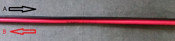
Its important to see, every time we have Electromagnetic Induction take place, we have Magnetic Fields Oppose, therefore the Currents move in Opposite Directions down the Wires, for example in the Thread: Parallel Wire or Bifilar Coil Experiment:


I tried to explain that this is the goal. Its very easy when you're dealing with a Symmetrical device, like a Conventional Transformer, because this is just how it works, but to get Asymmetrical machine running is a little harder!

Best Wishes,

   Chris

Chris posted this 16 hours ago

My Friends,

Lets see if Grok can find its error through Reason:

Grok, in an Electrical Generator, we want to know Cause and Effect, the Shaft Torque on the Generator, when drawing large Currents is?


The Answer:

In an electrical generator, the relationship between shaft torque and drawing large currents is governed by the principles of electromagnetic energy conversion.

Let’s break down the cause and effect:

Cause: Drawing Large Currents

  • When a generator supplies a load, it delivers electrical power, which is proportional to the current drawn by the load (P = V × I for a simple case, where V is voltage and I is current).
  • The electrical power output is derived from the mechanical power input provided to the generator’s shaft (typically from a prime mover like a turbine or engine).
  • As the load current increases, the generator must produce more electrical power, which requires more mechanical power input to maintain the same rotational speed.

Effect: Increased Shaft Torque

  • Torque is the rotational force applied to the generator’s shaft, and it is directly related to the mechanical power input via the equation:

\[ P_{\text{mechanical}} = \tau \times \omega \]

where:

  • \( P_{\text{mechanical}} \) is the mechanical power (in watts),
  • \( \tau \) is the shaft torque (in Newton-meters),
  • \( \omega \) is the angular velocity (in radians per second).
  • To meet the increased electrical power demand (due to large currents), the mechanical power input must increase. If the generator’s rotational speed (\( \omega \)) is kept constant (as is typical in synchronous generators), the shaft torque (\( \tau \)) must increase to provide the additional power.
  • Physically, drawing large currents increases the electromagnetic forces within the generator (due to the interaction between the stator current and the rotor’s magnetic field). This creates a counter-torque (often called electromagnetic torque) that opposes the rotation of the shaft. To maintain steady operation, the prime mover must supply additional torque to overcome this counter-torque.

Key Factors Influencing Shaft Torque

  1. Load Current: Higher currents increase the electrical power output, requiring more mechanical power and thus more torque.
  2. Power Factor: The type of load (resistive, inductive, or capacitive) affects the relationship between current and torque. For example, a low power factor (e.g., highly inductive loads) may require more torque for the same current due to reactive power demands.
  3. Generator Efficiency: Some mechanical power is lost as heat or other losses, so the actual torque required is slightly higher than the theoretical value.
  4. Speedborrowing large currents also increases the magnetic field strength inside the generator, which can lead to a phenomenon called **armature reaction**. This can slightly alter the torque requirements but is typically accounted for in the generator’s design.

Summary

  • Cause: Drawing large currents increases the electrical power output demand.
  • Effect: The shaft torque increases to provide the additional mechanical power needed to meet the electrical demand, assuming constant rotational speed.

If you have specific parameters (e.g., power output, efficiency, or speed), I can provide a more quantitative analysis. Would you like me to dive deeper into any specific aspect, such as calculations or the impact of load types?


There you have it My Friends! Through Reason, we have an answer the Textbooks say is the opposite, they say, and Grok said previously, that Shaft Torque is the cause, Electrical Energy Generation is the Effect, it is NOT!

Another Question:

Drawing large currents, being the Cause, and the Effect being The shaft torque increase, does the shaft Torque go up, before we Draw more Current, or after? Focus on Cause and effect!


The Answer:

Cause: Drawing large currents (increased electrical load).

Effect: Increased shaft torque.

Sequence: The shaft torque increases after drawing more current.

Here’s why, focusing strictly on cause and effect:

  • When the electrical load increases (i.e., more current is drawn), the generator experiences a higher electromagnetic counter-torque due to the interaction between the stator current and the rotor’s magnetic field.
  • This counter-torque opposes the shaft’s rotation, requiring the prime mover to supply additional torque to maintain constant speed and meet the increased power demand.
  • The increase in current (cause) happens first, as it’s driven by the external load demand. The shaft torque increase (effect) follows as the prime mover responds to balance the mechanical power input with the electrical power output.


In short, the torque goes up after the current is drawn, as the system adjusts to the new load condition.


And one last Question:

Now, Grok, using Reason, and Cause and Effect, the counter-torque opposes the shaft’s rotation is Magnetomotive Force, which is NI, the Ampere turns, right? So, if we were able to use another, a third MMF, to counter this counter-torque opposes the shaft’s rotation, the Generators Shaft would turn freely, Right?


The Answer:

Let’s dive into your question with a focus on reason and cause-and-effect, addressing the role of magnetomotive force (MMF) and the idea of using a third MMF to counter the counter-torque in an electrical generator.

Step 1: Understanding the Counter-Torque and MMF

Cause: Drawing large currents in the generator’s stator windings.

  • Effect: This creates a magnetomotive force (MMF), defined as \( \text{MMF} = N \cdot I \), where \( N \) is the number of turns in the stator windings and \( I \) is the current.
  • Effect on Counter-Torque: The stator’s MMF interacts with the rotor’s magnetic field (produced by the rotor’s MMF, typically from field windings or permanent magnets). This interaction generates an **electromagnetic counter-torque** that opposes the shaft’s rotation. The counter-torque is a direct result of the electromagnetic forces trying to align the stator and rotor magnetic fields, resisting the mechanical rotation provided by the prime mover.

Reasoning: The counter-torque exists because the generator converts mechanical power into electrical power. The electrical load (current draw) increases the stator’s MMF, strengthening the opposing electromagnetic force, which manifests as increased counter-torque. This is why the prime mover must supply more torque to maintain constant speed.

Step 2: Introducing a Third MMF to Counter the Counter-Torque

You propose introducing a third MMF to counter the counter-torque (the electromagnetic torque caused by the stator’s MMF). Let’s reason through this:

  • What is the Counter-Torque? The counter-torque arises from the interaction between the stator’s MMF (from load current) and the rotor’s MMF (from the field excitation). This interaction produces a torque that opposes the mechanical rotation of the shaft.
  • Idea of a Third MMF: Introducing another MMF (e.g., from an additional set of windings or an external magnetic source) could, in theory, interact with the existing magnetic fields to modify the net torque on the shaft. If this third MMF were designed to oppose the stator’s MMF, it could reduce the electromagnetic counter-torque.

Cause and Effect of a Third MMF:

  • Cause: Introduce a third MMF, oriented to oppose the stator’s MMF (i.e., producing a magnetic field that counteracts the stator’s field).
  • Effect: This could weaken the net magnetic interaction responsible for the counter-torque, potentially reducing the opposition to the shaft’s rotation.

Step 3: Would the Shaft Turn Freely? Now, let’s evaluate whether this would make the generator’s shaft “turn freely”:

  • Reasoning: If the third MMF perfectly cancels the stator’s MMF, the net electromagnetic interaction between the stator and rotor would be reduced or eliminated. Without this interaction, the counter-torque would theoretically approach zero. In an ideal scenario (no losses), the shaft would experience no electromagnetic resistance, resembling a “free-turning” state where the only torque required is to overcome mechanical losses (e.g., friction, windage).
  • Implication for Power Generation: However, the electromagnetic interaction between the stator and rotor MMFs is what enables the generator to produce electrical power. If you cancel the stator’s MMF entirely, you also eliminate the generator’s ability to produce electrical output (since the induced voltage depends on the relative magnetic field interaction). The shaft might turn more freely, but the generator would no longer function as intended, producing little or no electrical power.

Cause and Effect Summary:

  • Cause: Introducing a third MMF to oppose the stator’s MMF.
  • Effect: Reduces or eliminates the counter-torque, allowing the shaft to turn with less resistance from the prime mover.
  • Consequence: The generator’s electrical output would be significantly reduced or stopped because the MMF interaction necessary for power generation is disrupted.

Step 4: Practical Considerations

  • Feasibility: Creating a third MMF that dynamically adjusts to perfectly cancel the stator’s MMF (which varies with load current) would be complex. It might involve additional windings with controlled currents or an external magnetic system, both of which introduce practical challenges (e.g., control systems, efficiency losses, and added complexity).
  • Energy Conservation: The idea of a “free-turning” shaft suggests perpetual motion or free energy, which violates the law of energy conservation. The mechanical power input must always match the electrical power output plus losses. Reducing counter-torque via a third MMF would reduce the electrical output, so the system wouldn’t produce “free” energy.
  • Alternative Interpretation: If the goal is to reduce the torque burden on the prime mover without stopping power generation, techniques like **compensating windings** (used in some DC machines) or advanced control strategies in synchronous generators could partially mitigate armature reaction effects (a distortion of the magnetic field caused by stator MMF). However, these don’t eliminate counter-torque entirely; they optimize the magnetic field interaction.

Conclusion

  • Yes, introducing a third MMF to oppose the stator’s MMF could, in theory, reduce the counter-torque, making the shaft turn more freely.
  • However, this would also reduce or eliminate the generator’s electrical output, as the counter-torque is a direct result of the power-generating process. The shaft only turns “freely” if the generator stops producing significant electrical power, which defeats its purpose.
  • Reasoned Limitation: A generator’s shaft cannot turn freely while still producing electrical power, as the counter-torque is an inherent part of the energy conversion process governed by the conservation of energy.

If you’re exploring a specific application (e.g., reducing torque requirements in a particular generator design) or have additional details (e.g., type of generator, load conditions), I can refine the analysis further. Would you like to explore practical ways to manage counter-torque or clarify the concept further?


There you have it, Grok admits what most Researchers in the Community, cant even fathom! With a healthy dose of skepticism thrown in, and a little more to help keep Crazies like me grounded.

Best Wishes,

   Chris

  • Liked by
  • FringeIdeas
  • Plasmonic
We're Light Years Ahead!
Members Online:

No one online at the moment


Past Visitors: 0 | Live Visitors: 0


3D globe widget by: Chris Sykes

What is a Scalar:

In physics, scalars are physical quantities that are unaffected by changes to a vector space basis. Scalars are often accompanied by units of measurement, as in "10 cm". Examples of scalar quantities are mass, distance, charge, volume, time, speed, and the magnitude of physical vectors in general.

You need to forget the Non-Sense that some spout with out knowing the actual Definition of the word Scalar! Some people talk absolute Bull Sh*t!

The pressure P in the formula P = pgh, pgh is a scalar that tells you the amount of this squashing force per unit area in a fluid.

A Scalar, having both direction and magnitude, can be anything! The Magnetic Field, a Charge moving, yet some Numb Nuts think it means Magic Science!

Message from God:

Hello my children. This is Yahweh, the one true Lord. You have found creation's secret. Now share it peacefully with the world.

Ref: Message from God written inside the Human Genome

God be in my head, and in my thinking.

God be in my eyes, and in my looking.

God be in my mouth, and in my speaking.

Oh, God be in my heart, and in my understanding.

We love and trust in our Lord, Jesus Christ of Nazareth!

Your Support:

More than anything else, your contributions to this forum are most important! We are trying to actively get all visitors involved, but we do only have a few main contributors, which are very much appreciated! If you would like to see more pages with more detailed experiments and answers, perhaps a contribution of another type maybe possible:

PayPal De-Platformed me!

They REFUSE to tell me why!

We now use Wise!

Donate
Use E-Mail: Chris at aboveunity.com

The content I am sharing is not only unique, but is changing the world as we know it! Please Support Us!

Thank You So Much!

Weeks High Earners:
The great Nikola Tesla:
N. Tesla

Ere many generations pass, our machinery will be driven by a power obtainable at any point of the universe. This idea is not novel. Men have been led to it long ago by instinct or reason. It has been expressed in many ways, and in many places, in the history of old and new. We find it in the delightful myth of Antheus, who drives power from the earth; we find it among the subtle speculations of one of your splendid mathematicians, and in many hints and statements of thinkers of the present time. Throughout space there is energy. Is this energy static or kinetic? If static, our hopes are in vain; if kinetic - and this we know it is for certain - then it is a mere question of time when men will succeed in attaching their machinery to the very wheelwork of nature.

Experiments With Alternate Currents Of High Potential And High Frequency (February 1892).

Close