Hy guys,
thank you for your time and comments to me. I am wery gratful for your guidance. I suspected that resonant frequency is realy to high, but when i found multi of them i thot it is principle of harmonic.
1.) To high frewuency?
Yes it is,.... realy to high. This is the fact. Now i think that al the frequency witch i found are harmonic frequency perhaps.
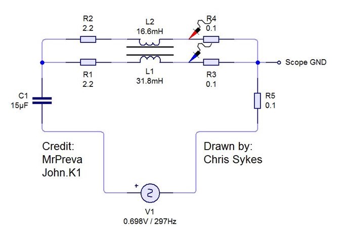
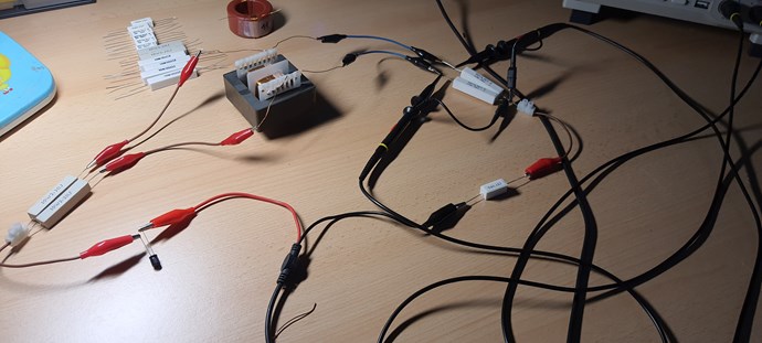
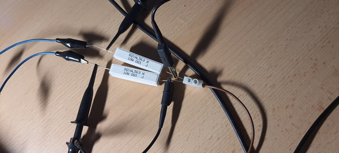
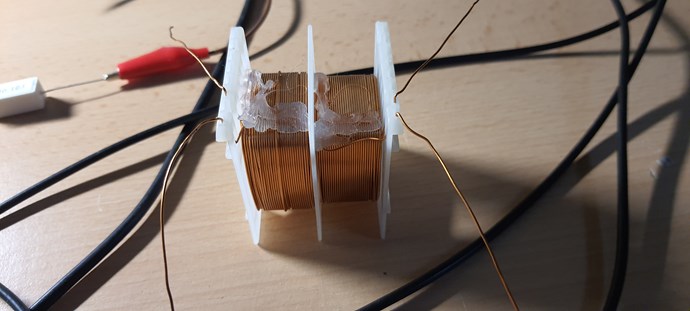
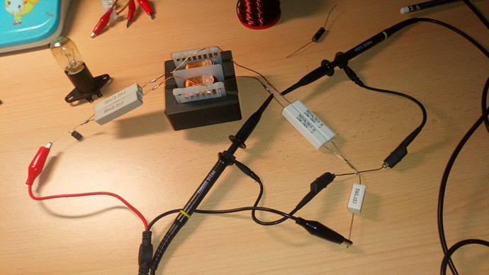
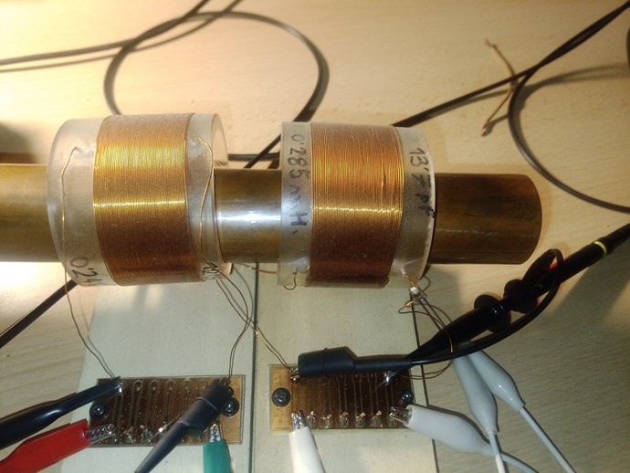
I mesured inductance of two coils with RLC meter. This meter is china cheepie,.. so i dont now how mutch to trust thise numbers.
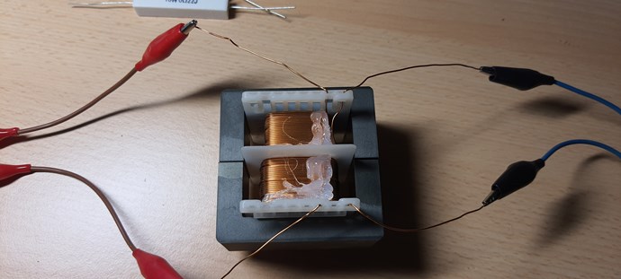
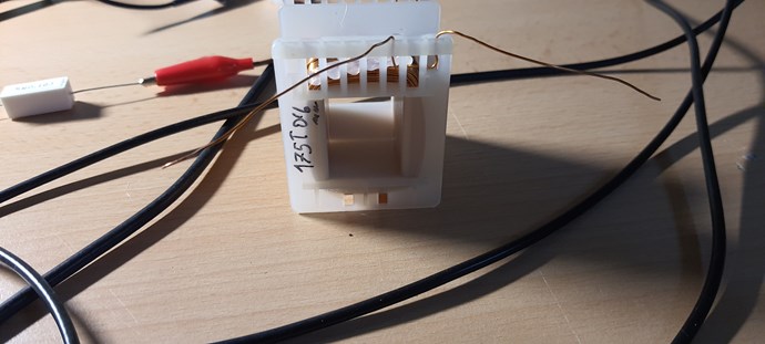
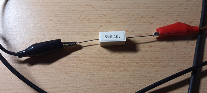
L1 175T 0.6mm 71.3mH, 1500qF
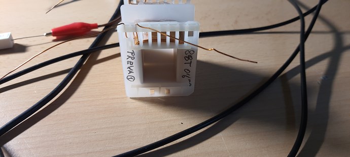
L2 88T 0.6mm 17.1mH, 790qF
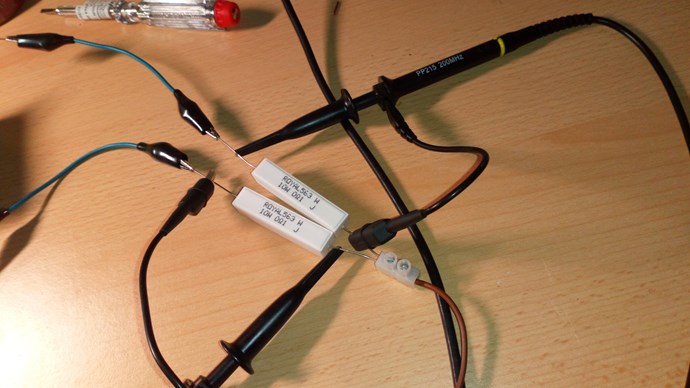
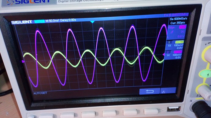
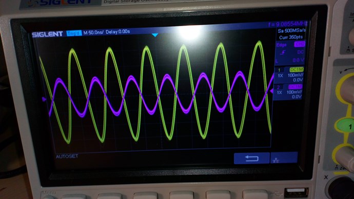
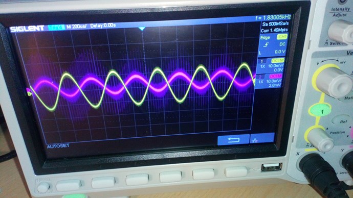
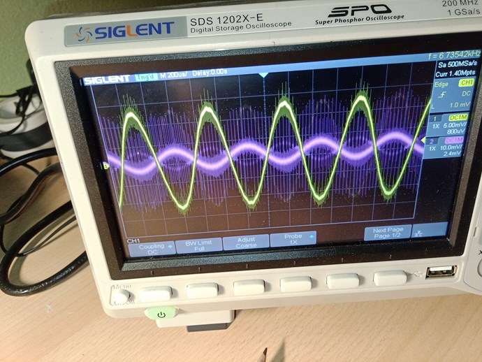
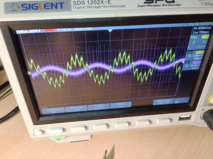
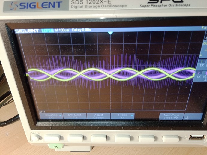
I put osciloscope and signal generator to one coil ( L1 - 175T) and sweep frequency and i stop it realy fast, becose resonance response skyroket. Then i do it manualy. When i found resonant frequency of coil L1 (75T ch2-violet color) i turned on the L2,(88T ch1-yelov color) to se what is relationship betwen both.
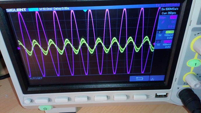
Then i loked for resonance frequency on L2 and turn on the ch1 to look relatinship betwen them.
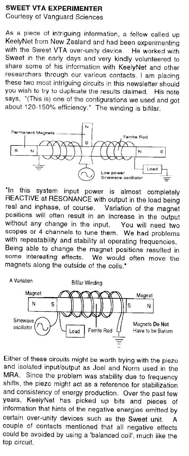
Fferite core is 3C94 and it is ok to 1mhz,if my memory serves me well. ( i buy it for thise reason)
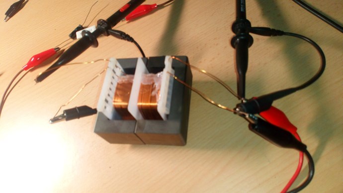
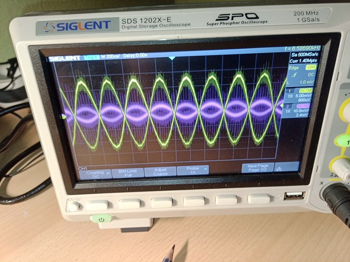
hok it up to L1 175T 0.6mm
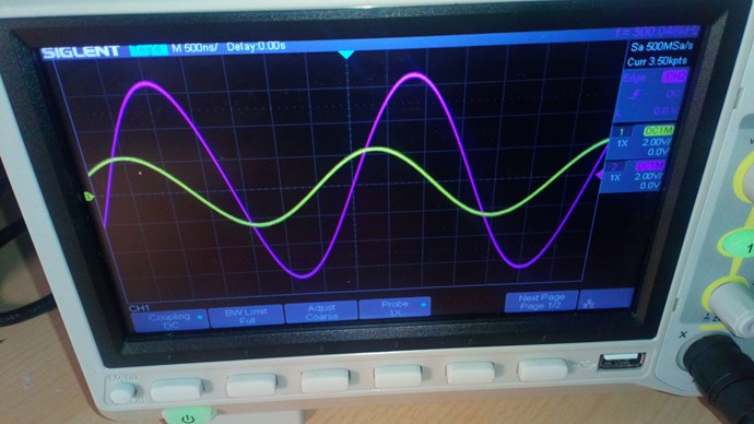
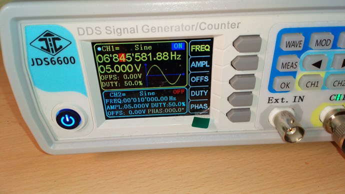
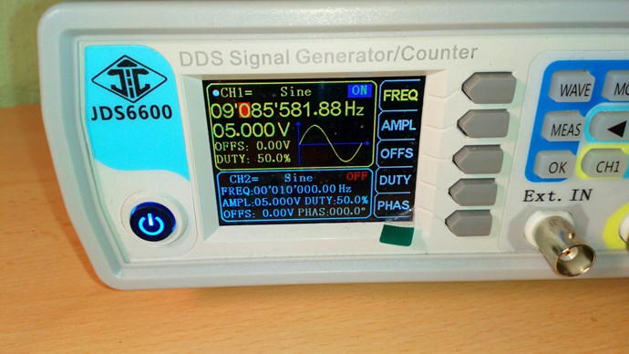
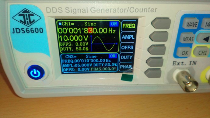
ch2 175T L1 violet in resonance at 300,050Khz
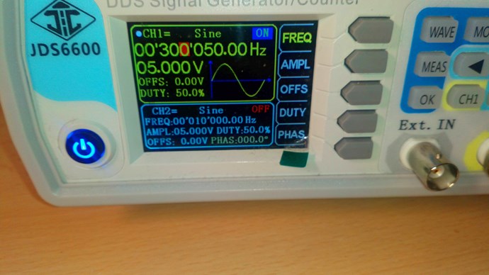
to confirm signal generator output
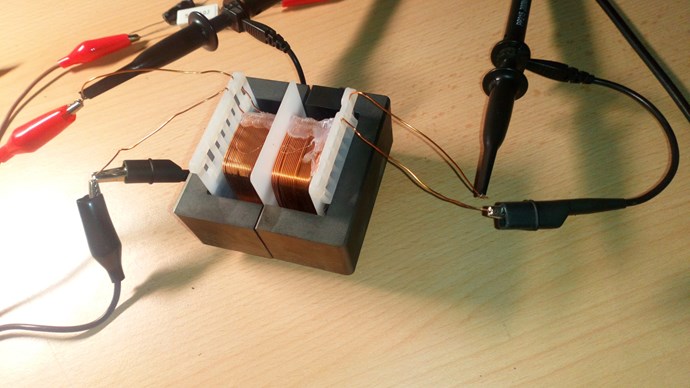
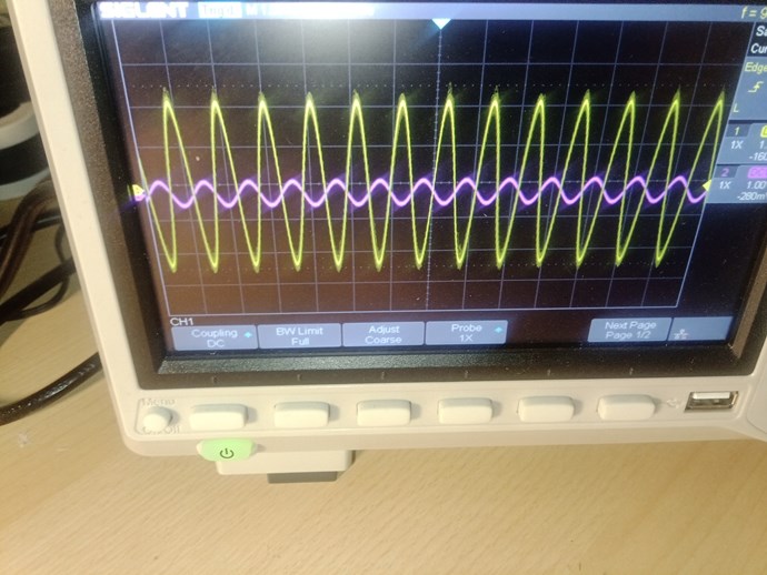
hok it up to L2 88t 0.6mm
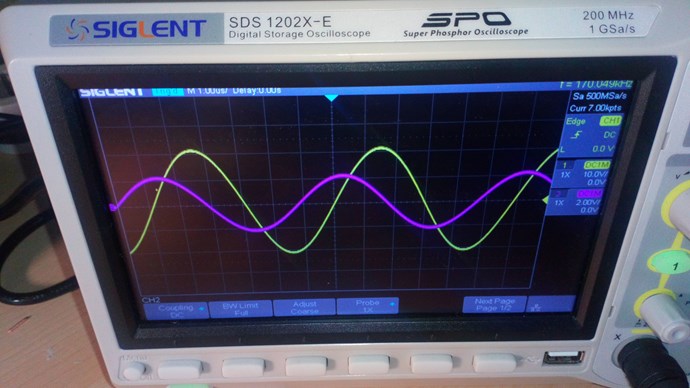
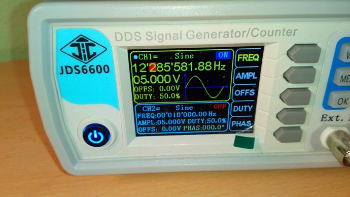
ch1 88T L1 yelov in resonance at 170,050Khz
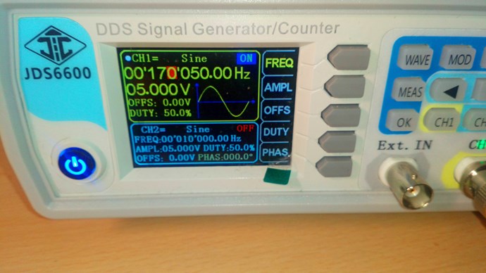
to confirm signal generator output
So here can we see resonant frequency of L1 and L2 and both relationship to the other coil which are not in resonance.
My question in my mind is as folows:
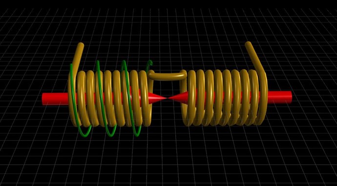
- if we need to have 180 degre of phase shift betwen both coils in transformer why we dont do it with:
a: phase shifter ( perhaps it is to complicated and it cant hold high curents)
b: special cable - we take cable with isolation in whitch is teflon and hok it up as in picture
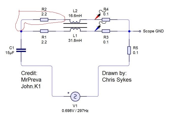
We take long cable, and cut it back so mutch that we get 180 degre out of phase on the osciloscope.
- The whole magic is to put two signal out of phasefor 180 degrees, yes? Becose they ad? This is curent. But my question is what is going on with voltage. If voltage of one coil is out of phase a lot then you dont get power? Aktiv power and this stuf. What is with this stuf then?
- If i understand corectly preva exsperiment is circulating for exsample 2.8A in and out of transformer but in transformer there is circulating axses of curent 5.1-2.8 =2.3. This 2.3 is directly dependent from phase shift 180, not big phase shift betwen voltage and curent in coil L1 and L2 ( aparent and real power). Is this corect.
- i loked around to buy amplifier for this exsperiment, that i can amplify signal from signal generator. Sad thing is that i got offer for 4K euros for this amplifier. Problem is frequency dependent.... . So i loked for op amp and i found power op amps in range to 10 a or more powerful to 100a. But problem is that they are exspencive. When i loked frequency dependance, it goes like so more buck biger thefrequency band. Can i get some info what do you use for amplifing the signal from signal generator please.
- If i look this problems around frequency, input curent and voltage and specialy resonance response the only thing in my mind that can save my ass is go old school. With this i mean, buy a deep cycle acumulator, hok it up to tru sine inverter, huke it up to variac, hok it up to variable oil or vacum capacitor for high voltage and i have voltage regulated ac sinosuidal sorce with frequency regulation option becose of variable capacitor. Thise amplifiers are realy costly becose higher the frequency higher the buck you need.
I have some problems geting suplys is it like nobady going to work enywere, i dont now.
My apologies becose things are in delay, i need to buy some stuf and this is not easy eny more.
One more thing, when i loked for resonance frequency for L1 coil on ch2 175T when i go to 1kHz and i went belou this number to around 975Hz signal generator had a realy strange sound coming out of it, more i lower frequency more louder it became, so i stop going lower. What is this, some resonance frequency of some part in signal generator?
Best wishes
elektrondiger