Inductance ( L ) is the Rate at which Amperes can flow through the Coil in Time, this is defined as:
L = di / dt
One Henry is where One Ampere transitions the Coil in One Second. With Back E.M.F:
L = ε / di / dt
Where ε is the Back E.M.F, restricting the Current Flow, created by the change in Current that produced the E.M.F.
Confused?
Keep reading:
The Impedance of a Coil is calculated: Impedance ( Z ) = Voltage ( V ) / Current ( I ) and is given in units of Ohms ( Ω ).
Complex Impedance has two components, real and imaginary. An example of this would be: Z = R +j X
Where:
- DC Resistance ( R ) = Real Component.
- Reactance ( X ) = Imaginary Component.
- +j = Voltage Leading.
- -j = Voltage Lagging.
All components are real components, observable Circuit conditions.
Reactance ( X ) is composed of both Capacitive Reactance ( XC ) and Inductive Reactance ( XL ). In an LC Tank Circuit, at Resonance, XC and XL are equal and are said to cancel each other out. Thus in the LC Tank Circuit, the Capacitors Charge ( Q = C / V ) transforms into Magnetic Field ( B = μnI ) at maximum efficiency, which is measured as Quality Factor ( Q ) = Reactance ( X ) / Resistance ( R ).
So, if Reactance ( X ) is very low, say: 0.00001, and Resistance ( R ) is very low, say: 1.0, then Quality Factor ( Q ) = 0.00001 / 1.0 = 0.00001
NOTE: Inductive Reactance ( XL ), is directly related to Faradays Law of Electromagnetic Induction!
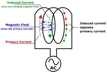
Faradays Law of Electromagnetic Induction: E.M.F = -N dPhi / dt, which is actually Back E.M.F, because of Self Induction inside the Coil, between the turns, this resists the Flow of Current, B.E.M.F = XL = ωL = 2pifL
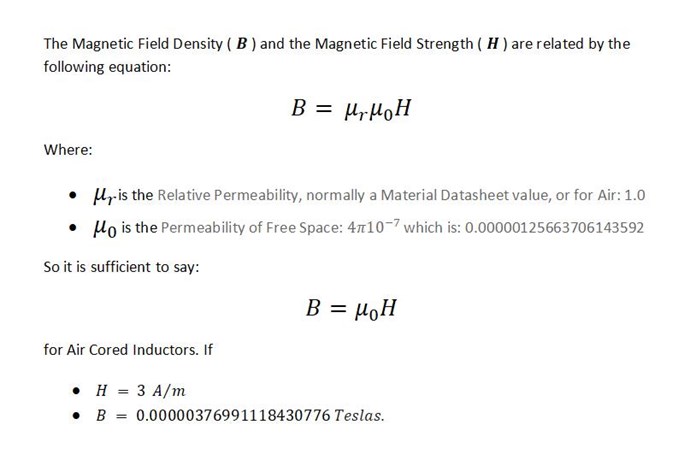
Also, remember, B and H are related in the following way:
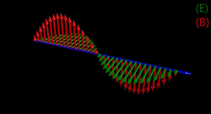
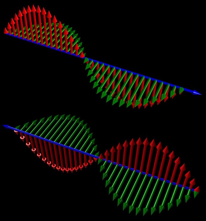
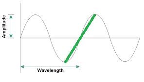
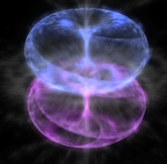
We know, the Cycle of the Transformation from Electric to Magnetic can be seen in Quadrants:
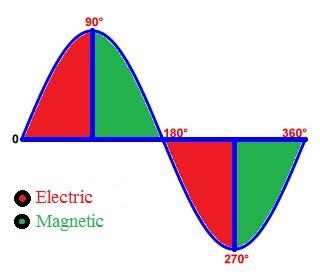
Red is Charge on the Capacitor ( Q = C / V ) charging the Inductor ( B = μnI ). At 90 degrees, the Capacitor has fully charged the Inductor, and the Inductor now Charges the Capacitor as the magnetic Field Changes in Time in the proximity of the Turns, yes Faradays law of Electromagnetic Induction again.
In an LC Tank Circuit, we see losses, Damping Factor ( ζ ) Zeta, and we see a typical decrease in the Amplitude of the Oscillations in an LC Tank Circuit:
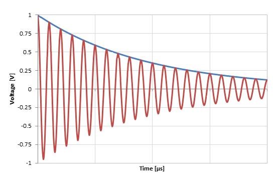
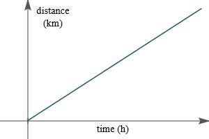
Inductance and Reactance all stay Linear, losses are not recoverable, and we see the Oscillations taper off.
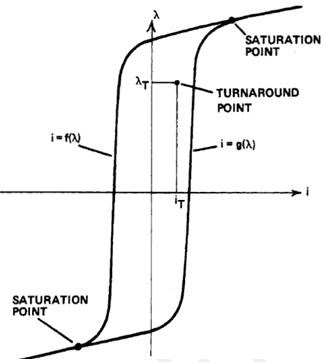
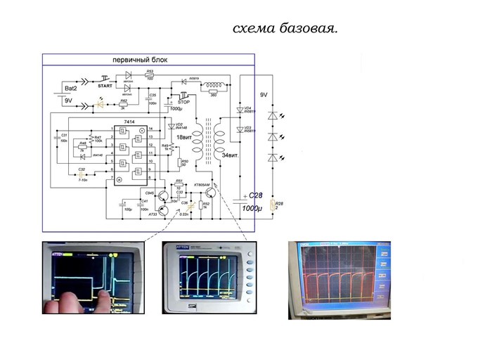
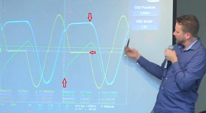
However, what is required to change, to Non-Linear Inductance? How can we see changes, enough to see a wave form like so:
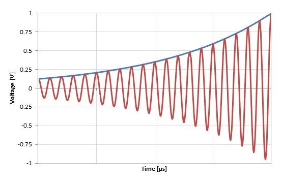
Knowing what we know, we must have any one of the above variables change. An experiment I have done, does show how this can be achieved: Reduced Impedance Effect
I do not agree entirely with Jim Murray. He has found a lot of what I have, his Transforming Generator does show the same effect as my Reduced Impedance Effect:
In the following video, if you listen carefully, Jim does say what I have, I = dL / dt:
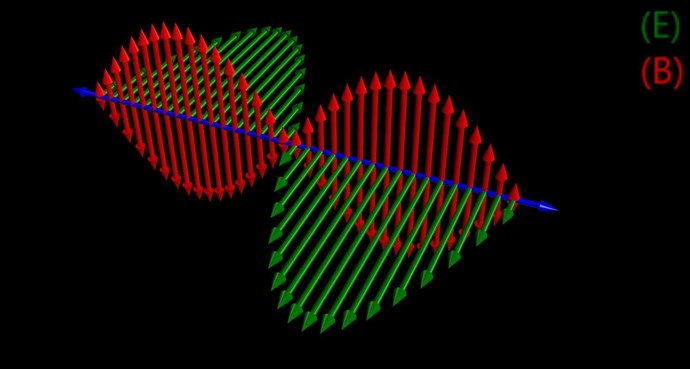
So, it is possible, at 90 Degrees, we can change the Circuit, make the Circuit change, with The Reduced Impedance Effect, or other effects, to become more Re-Generative, or Less lossy.
But, please remember, we must not touch the Circuit between 0 and 90 degrees, and between 180 and 270, all Red Zones are No Go Zones!
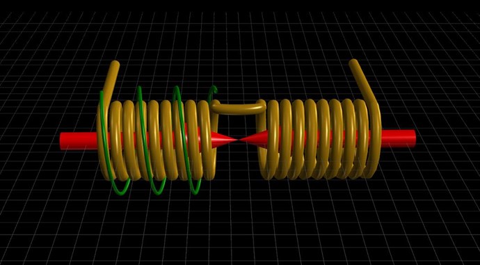
By changing the Systems Inductance or any part of the Coils parameters, which in turn changes the Inductance, is a common theme we have seen a lot of.
The works of Don Smith, Floyd Sweet, Andrey Melnichenko, Clemente Figuera, and many others all take advantage of these effects.
Also similar to Zanzals Un-Named Device, also a Video Zanzal has shared:
This Technology is everywhere, its there for the taking, it only requires you understand these concepts and then apply them!
I think the term: Non-Linear Inductance is perhaps not entirely adequate for the description of what's actually going on. So I ask you, please think broadly about this and do not confine yourself to the specific of Inductance.
What is true, if we change the Rate at which Current can transition the Coil, we have also changed the Inductance!
Supporting Links:
Chris