My Friends,
You have been lied to, mislead, and swindled, by self proclaimed gurus, you those members of other forum's, they are absolutely NOT qualified, never will be, yet they have had a grasp on your direction for decades.
The Power of Observation, key to understanding and furthering our technologies, advancing as a Species, hopefully together.
We all know the Floyd Sweet VTA Schematic, we have seen it a million times, but have we closely studied and made critical Observations:
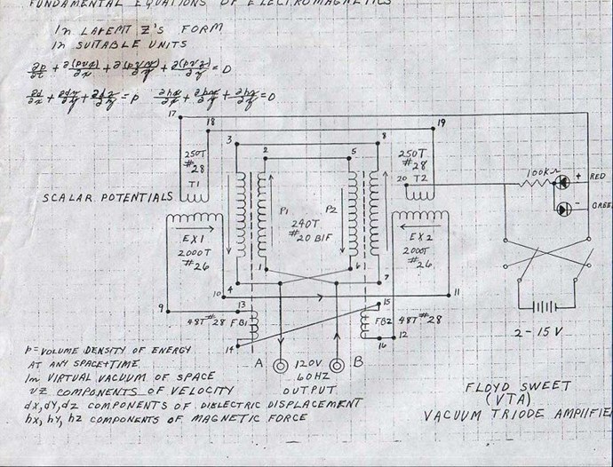
A short list of some Key Observations:
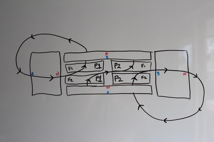
- P1 supplies a Voltage and therefore a Current to one coil in P2 and vice versa.
- At-least two signals at any one time is present, one from FB1/2 and another from the opposite Power Coil.
- The Arrows indicate the Bucking, which ties in with the below quote.
- The VTA was started by a battery, and stopped by momentary disconnection of the Power Coils.
Quote
FIELD SUPER-POSITION AND THE VACUUM TRIODE
Electromagnetic induction with no measurable magnetic field is not new. It is well known that in the space surrounding a properly wound toroidal coil there is no magnetic field. This is due to the superposition of the fields. However, when alternating current is surging through a transformer an electric field surrounds it. When we apply the principle of superposition to the vacuum triode it becomes more obvious how the device is in fact operating.
The principle of superposition states that; "In order to calculate the resultant intensity of superimposed fields, each field must be dealt with individually as though the other were not present". The resultant is obtained by vector addition of each field considered singularly.
Consider for a moment the construction of the triode which includes the bifilar coils...
When the current in one half of the conductors in the coils (i.e., one of the bifilar elements in each coil) of the device is moving up, both the current and the magnetic field follow the right-hand rule.
The resultant motional E-field would be vertical to both and inwardly directed.
At the same time the current in the other half of the conductors in the coils is moving down and both the current and magnetic field follow the right-hand rule.
The resulting motional E-field is again vertical to both and inwardly directed.
Thus, the resultant field intensity is double the intensity attributable to either one of the set of coil conductors taken singularly.
Expressed mathematically: E = (B x V ) + ( -B x -V ) = 2 ( B x V )
You will note: E = (B x V ) + ( -B x -V ) = 2 ( B x V ) is this statement, in long form:
Quote
If the directions of the two signals are such that opposite H-fields cancel and E-fields add, an apparently steady E-field will be created. The energy density of the fields remain as calculated above, but the value of the E-field will double from E / 2 to E.

My Friends, can we Cross Reference these observations? Yes we can!
Andrey Melnichenko's GLED uses the very same facts, also the same with Kapanadze's machines.
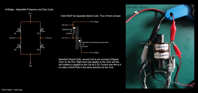
I already tried to show you all, Tinman's RT V3 also uses the very same effects by injecting a small current into one POC at the right time:
I said:
Look For Effects - I have always said this, this is how I found this path! Some effects to look for:
Ref: Chris
I gave you all, a very simple experiment a long time ago:
Some of my Pulsed DC work was documented here: Akula0083 30 Watt Self Running Generator.
The CLOSE Observation of this experiment was a real blessing for me! I found some very important aspects to Bucking Coils in the experiment! Other very bennificial Experiments also helped!
You will obtain success if you follow these key observations, which are Intuitive yet contrary to what we know. I will have more on this very soon!
Best Wishes,
Chris