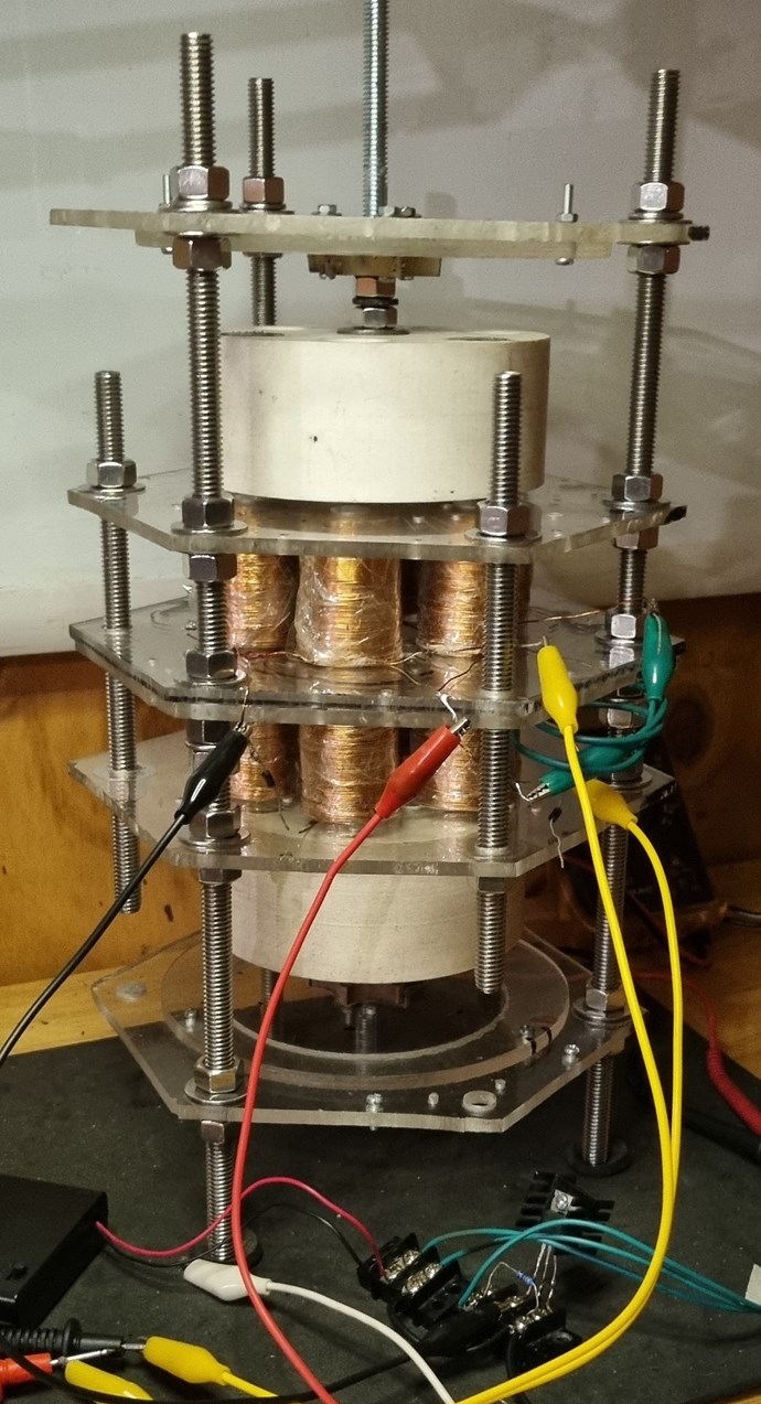
After a fun few weeks of testing I'm now pulling 140VAC from a 14W input... inadvertently, by having the POCs within the rotors, I get a much increased pulse as the pulsing POCs work together. At the moment the pulsed POCs are wired and pulsed in parallel, but the plan is to split the switching so that the ~70V of EMF can be bucked. A 36V/.5A return will make this a self runner.
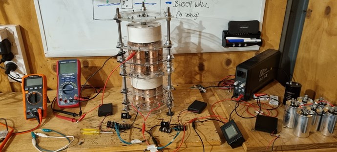
Without a scope (Siglent SDS1104X-E is on the shopping list), I only have multimeters to roughly gauge how the POCs are behaing.
For the generator POCs, with diodes for direction in place, I can clearly see the load of 7x12V mini edison globes dragging down both coil sets relatively evently from 60V > ~50, when placed on the native wound coil set. But the same load again on the regauged coil set, sees it drop as low as 27V and 36V on the other side. So definitely levels of interaction going on here.
I'm wondering whether I need to make a simple mechanical commutator to pulse the re-guaged set of coils to 'trick' the current to flow in the opposite direction at the right tme. Something a scope will help with.
The really exciting part of this, if I were to pulse from outside of the rotors, my output would double to 280V across the dozen coils within the rotors. And further, if I loaded the other half of the rotors with opposite magnets, I could potentially double again by alternating flux flow.