Introduction:
The Modular switching tool is a very practical commutation device for research on electromagnetics. It's features make it especially useful for pulsing DC applications, Half bridge and H bridge configurations, floating Hi or low side switches, coil shorting and other similar techniques.
The power switch modules are provided with a single IGBT rated for 25A 1200V max. , which can be easily exchanged for a MOSFET Device, convenient for high frequency applications, by using the practical screw connectors. Additional screw connectors are provided for a surge protector, and connections to the external circuits. As the module employs an optical isolated driver, and the driver power supply is also galvanically isolated by transformers , the switch can be used completely floating, either in High or Low side position , combined with aditional switch modules as half or full bridge topology and more.
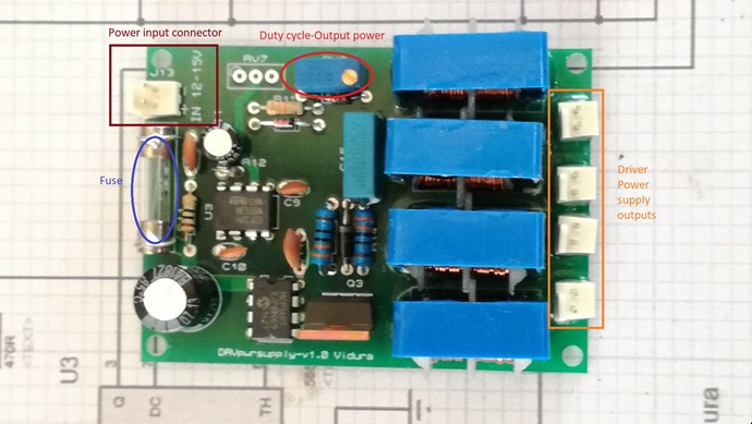
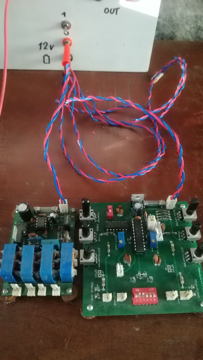
The Driver power supply module is another part of the tool, which provides four outputs to feed the required power for the drivers of four power switch modules. This device has to be powered with 12-15v dc, like a small lead-acid battery or a PSU.
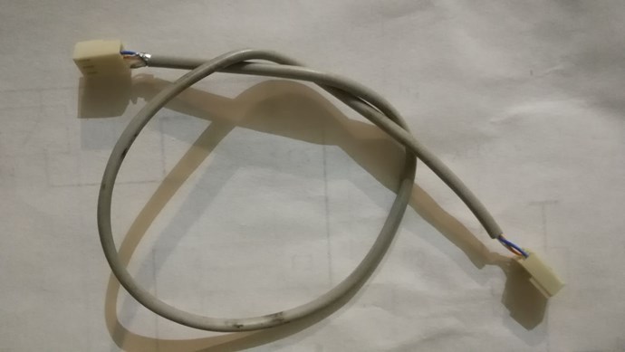
With this two basic module types the tool can be used feeding the signals from a standard signal generator or an Arduino board. A set of connectors is available for this kind of usage.
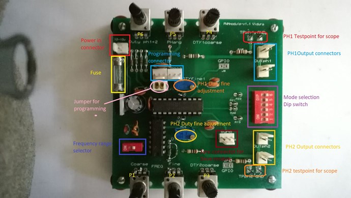
The next component is the Master PWM module. This is a specially designed oscillator which provides two phases of square wave signals, and have some unusual properties as the combined analogous and digital control feature. It is based on a PIC16hv785 microcontroller, this MC has a internal two phase PWM peripherical with infinite resolution analogous duty cycle control. Also the frequency of the PWM is analogous adjustable , and thus have infinite resolution as well. This advantages are combined with digitally controlled features like the 5 bit resolution of the Phase angle, complementary outputs for half or full bridge drive with adjustable deadtime, or individually adjustable duty cycles for both phases. The device have various ranges of frequencies and duty cycles , and covers a spectrum from a few Herz up to 350khz. Also a connector for in circuit programming is on the module, for those with knowledge in PIC programming more possibilities like an additional CCP peripherical, OpAmp's and timers and a synchronisation feature for a slave module, for adding two more phases, are available in the MC.
The slave PWM module:
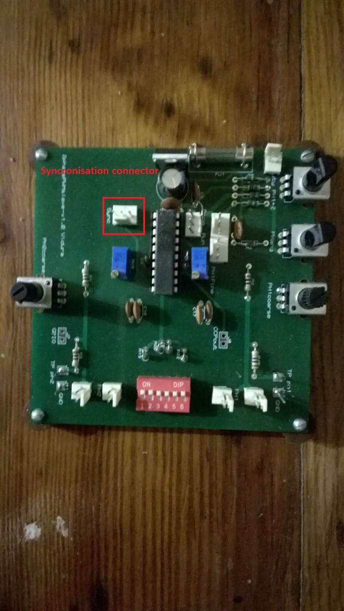
This is a module which is intended as an extension, it adds two more phases synchronized with the master PWM,
It is basically identical with the master PWM, with the only difference that it do not have an own clock oscillator, as it is designed to be connected and synchronised to the master PWM module via a sync connector.
Hardware overview:
1.Power switch module: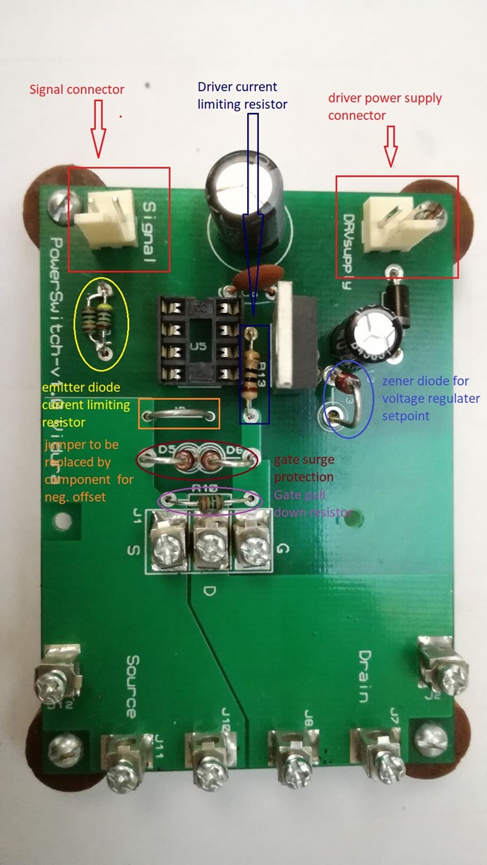
This is a view of the Power switch PCB with identifiers for some components with specific functions.
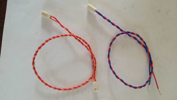
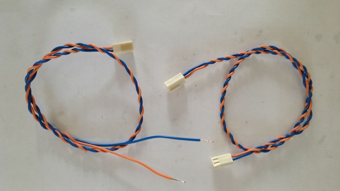
Signal connector: to connect the signal source, which can be the PWM module, a signal generator or similar. The positive terminal is on the right side in this view, the slot side of the connector. The Signal connector wires have Orange-blue colour identification. (orange corresponding to the positive conductor)
Below it remarked in yellow the current limiting resistor for the emitter diode of the driver IC. It is configurated for a voltage of 5V, as output from the PWM modules. Using a signal generator it should be set to the same voltage, although for some models it might be necessary to rise it to 10-12 volt, you can put a 1 ohm resistor in the signal line and measure with the scope , to find the correct voltage setting for your SG. Be careful not to exceed 16mA, as the driver IC could be damaged by doing so. For some Arduino boards with 3.3V output the value of the limiting resistor should be changed to 180- 220ohm to achieve a reliable switching performance.
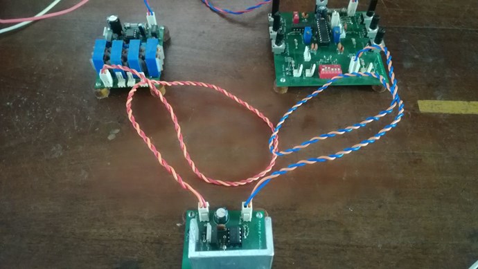
On the upper right side you find the Driver supply connector. Here the connector wire from the Driver power supply have to be placed. The corresponding connection wires are identified with red-orange colours. The Driver power supply delivers AC current at aprox.40V which is rectified and filtered in the Power switch module.
Below remarked in blue you see the zener diode for the voltage regulator, it defines the setpoint for the voltage limit for the driver IC. It is by default set to 17V (18V zener diode -1 voltage drop). The A3120 driver IC is capable to driving voltage up to 30 V, which is within the range of many IGBTs, But most MOSFETs have a max. Gate voltage of 18-20V, so the default regulation can be used for both types of switches. In the centre you see the deriver current limiting resistor, it has two functions, it prevents ringing on the gate and limits the maximum current drawn from the driver IC . The default value of 10 ohm should cover well most applications.
The Jumper remarked in orange colour is a special feature of the module, It can be replaced by Zener diode to achieve a negative offset switching, this special technique will be covered later in another chapter.
Remarked in red the gate surge protection, consisting of the two zener diodes D5,D6. Their function is limiting the gate voltage below 19V. This maximum value is adequate for MOSFETs, and although some IGBT can be driven with higher gate voltage, for most applications they will perform good with the default values.
Below it marked in violet you can see the gate pull down resistor, its function is to keep the switch in off state, for example when the driver supply power is turned off.
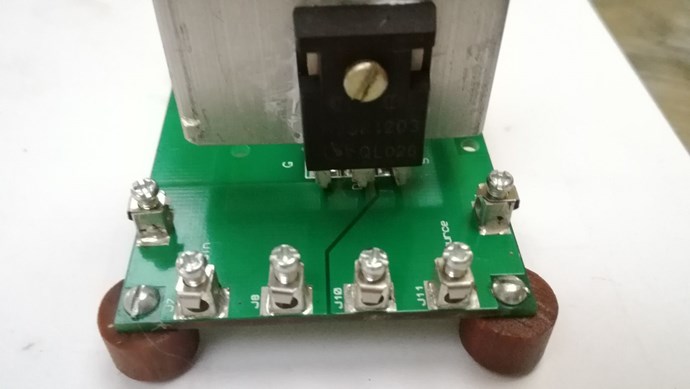
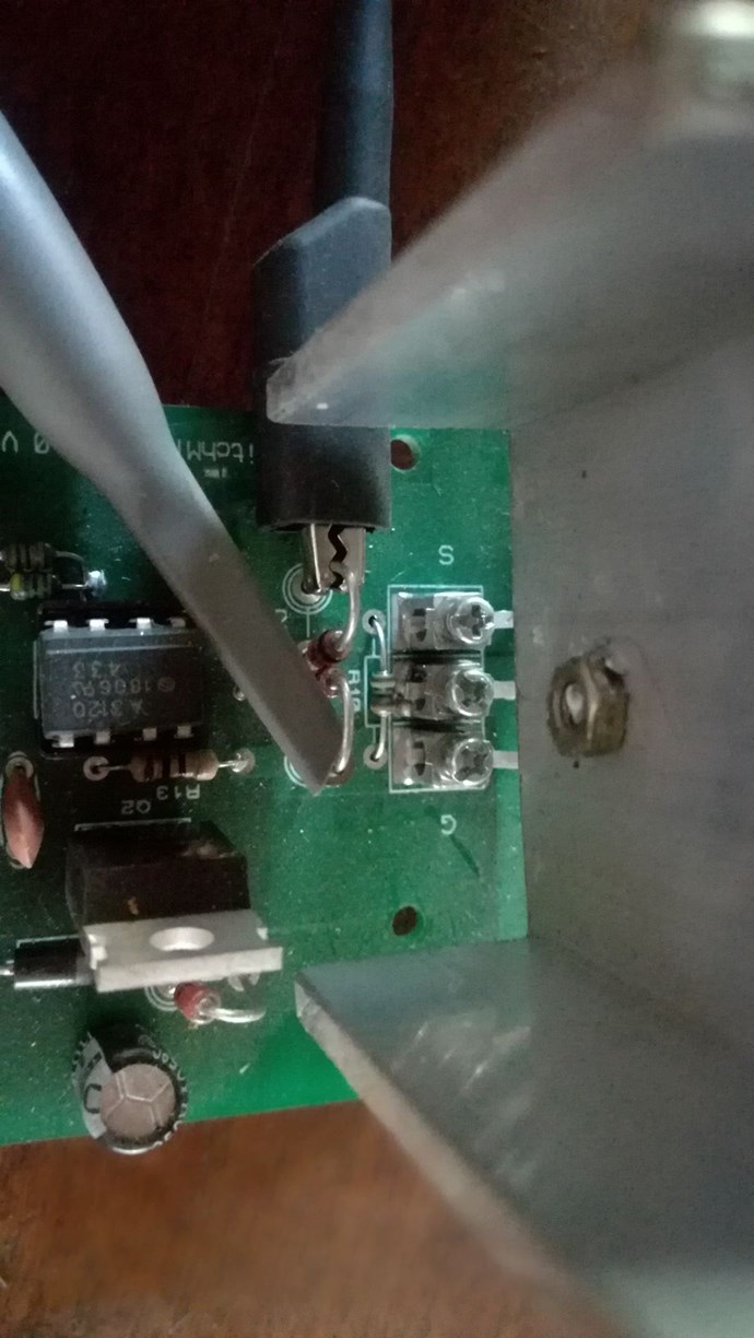
In this picture you can see the IGBT mounted in the module. Care must been taken to connect the gate to the corresponding terminal labelled with G. In your toolset you might have normal and mirrored versions of the switch module, the mirrored version have the IGBT on the opposite side of the heatsink, and the leads are bent to the opposite side to match the correct connectors. If you change the switch device assure to mount it in the correct position for each type of module. IGBTs and MOSFETs in TO247 or TO220 packing have the gate always on the left side looking at the front of the device.
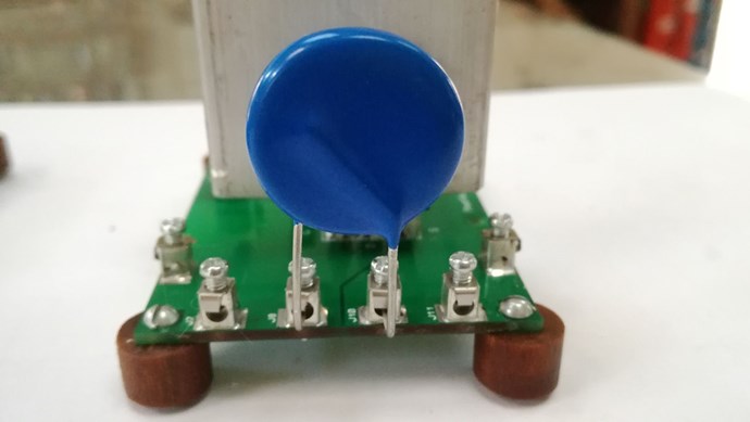
The Drain-Source surge protector. This is a very important part when you are switching inductors, as the BEMF spike would easily destroy the switch if not present. The default component is a MOV S14K275 witch has a max clamping voltage of 710V, this leaves a good safety margin to protect the IGBT (1200V max), but if needed it can be exchanged for a higher value up to a 420V rms MOV which clamps at 1120 Volts. If you change the switch look in the datasheet for the rated maximum voltage and use an appropriated surge protector for the new component. For lower voltage devices also a TVS diode can be used.
The optical isolated driver:
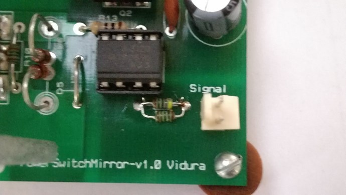
In this image you can see the optical isolated driver IC, if you remove it in any occasion be sure to mount it in the correct position like shown , the identifier stripe is always on the signal input side. If any signal source with a different voltage as 5V default configuration will be used , changing the current limiting resistor of the emitter diode may be required. Choose an adequate value to adjust the emitter current between 10 and 16 mA.
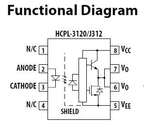
Below a functional diagram of the driver IC:
2. The Driver Power supply:
The module is designed as a floating power source for the Driver IC on the Power switch modules. The four separate output transformers covered with a dielectric coating are providing an galvanically isolation up to 4000Vrms. In the image below you can find the indicators for the connectors and the output power adjustment.
The module has to be connected to a 12-15Vdc supply, which can be a 12V lead-acid battery or a small PSU.
With the default regulation four modules mounted with MOSFETs of moderated total gate charge can been driven up to more than 200khz, rising the input of the supply module to 15v it supports even higher frequencies, the same applies if less modules are connected. If more driving power is required the duty cycle can be increased, by turning the preset potentiometer clockwise.
