Hey, I really like the videos! First off, manual calculation of complex wave forms is never the best option 😂 Kidding. Maybe you could teach me some math though.
I wanted to comment about your trying to calculate the duty cycle. What I'm about to share, I'm not trying to say is correct, but it's something I have needed to investigate further, and just have not. So as you are now going through the same thing, I figured we could open this up a little bit and try to progress together.
And again, sorry, I had found this information in a thread somewhere and for the life of me can't find it. It was just a small discussion tucked away somewhere. There is also a little relevant information in this video, which I'm guessing you have watched, but I thought I would bring it up here.
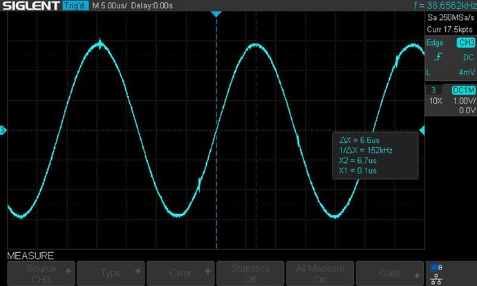
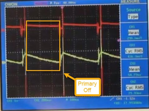
Anyway, your natural resonance of your coils as you say is 191.5 KHz. The rise time, or 1/4 of the cycle is 1.3 µS. So, my understanding is that this is the time period for the pulse, and it should not change. As you move down to lower frequency sub-harmonics, lets use half of Fres, being 95.75 KHz, you would still use 1.3 µS as the pulse time. Picture to help understand, showing two cycles, the whole length of time here would be one cycle of 95.75 KHz, if that makes sense. 
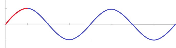
So we are still targeting the Fres of 191.5 KHz, with a 1.3 µS pulse at 95.75 KHz. Like the of pushing a swing, we are pushing once every two cycles, not on every cycle. Using sub-harmonics so we ensure the "push" time is always during the correct part of the cycle.
Now the issue here is that for 191.5 KHz the duty cycle at 1.9 KHz would be super small. If you get a chance, could you check your resonance and see if you can find a second, much lower, point where the coils resonate? For example I found resonant peaks on my coils at around 130 KHz and I think about 4.9 KHz, I'll stick with that for the example, with similar magnitudes. So I could use the 1/4 rise time duty cycle thing i just mentioned with 4.9 KHz and not shave my duty cycle off to nothing.
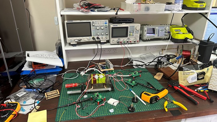
I've been wanting to do a few really basic experiments around this idea. Capacitor and one inductor of known values, find the resonance. Then switch to pulse and sweep around and find the peaks. Then try different duty cycles, etc. See how well the idea holds up. I just have not got around to it.
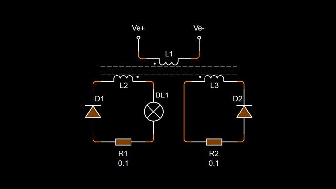
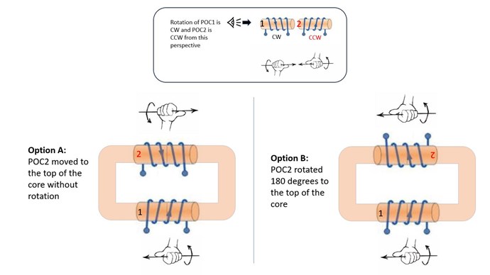
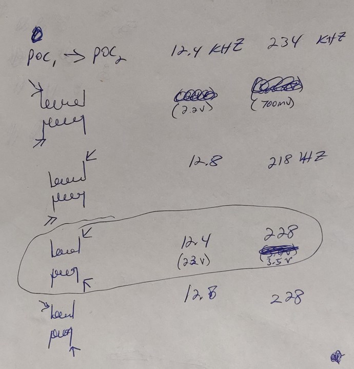
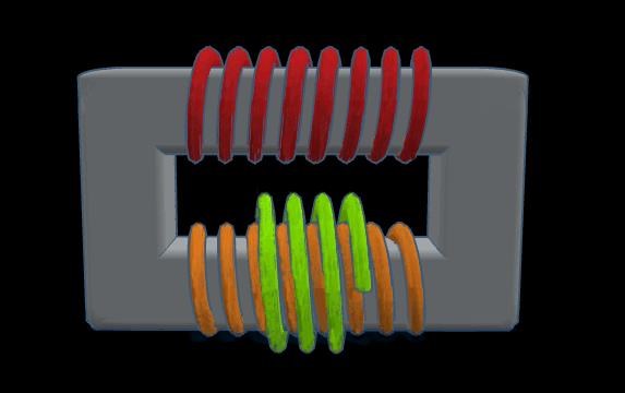
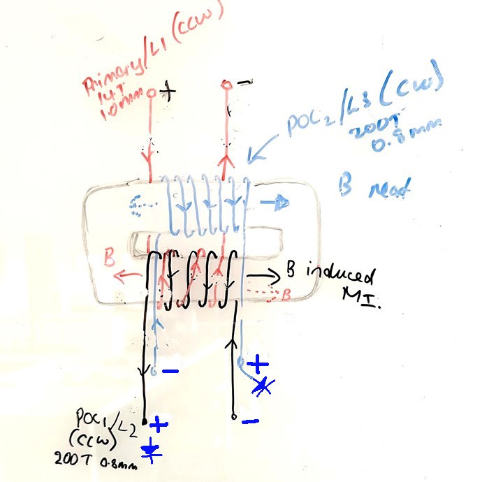
Also, the things Chris mentioned are important things to play with. The switching in/out of POC2 is helpful. On my setup I used a small metal bar which I'd drop in the light bulb fitting on POC2. Manually sweeping around the frequencies with different duty cycles, open (un-short) POC2, short, monitor the input current and the brightness of the bulb on POC1. At points you will see, when shorting, the light dims and the input increases. And not far away from there you should points where the bulb actually gets brighter and the input goes down, again when shorting. POC2 is then assisting the input. Then look at ways help facilitate this effect.
Also, just in passing, leaving both POC coils open and sweeping around, you can watch the amplitudes of the oscillations vary, it's interesting anyway, good way to get familiar with your coils.
Anyway, I need to run. Working, trying to type this, and watching sick kids at the same time. I hope I said everything I was thinking, and have not steered anyone off course. Again, don't abandon your thoughts on the duty cycle. Just wanted to give more to think about.
Hope to see more soon!
Marcel


.jpg?width=690&upscale=false)


