The Dot Notation
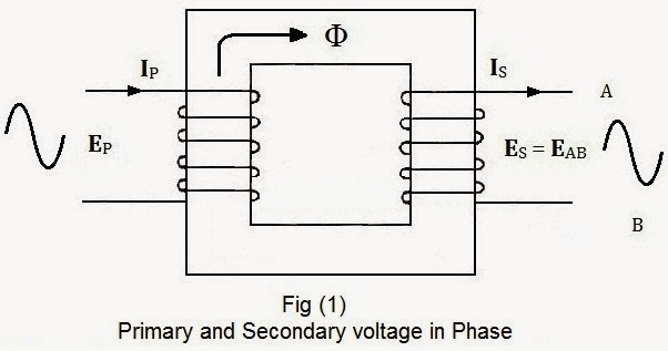
Generally, when we study about Transformers, we assume that the primary and secondary voltage and currents are in phase. But, such is not always the case. In Transformer, The phase relation between primary and secondary currents and voltages depends on how each winding is wrapped around the core.

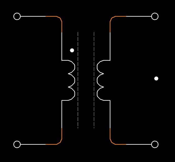
Refer to fig (1) and (2), you may see that the primary sides of both transformers are identical i.e. primary windings of both transformers wrapped in the same direction around the core.
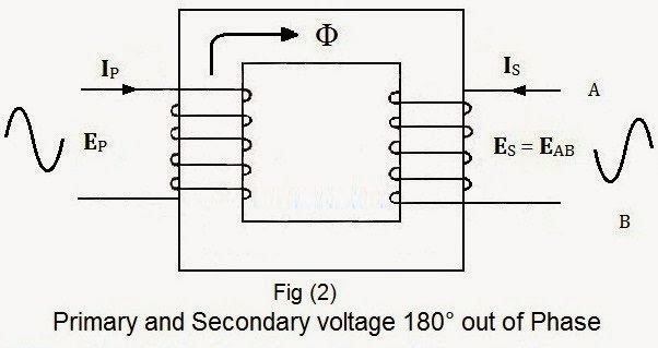
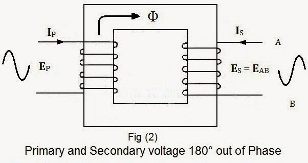
But in fig (2) you may notice that the secondary winding is wound around the core in the opposite direction from the secondary winding in fig (1).
Consequently, the voltage induced in the Secondary winding in fig (2) is 180° out of phase as compared with the induced voltage in secondary in fig (1) and the direction of secondary current (IS) is opposite from the primary current (IP)
So we see that
- The primary and secondary voltage and current are in phase in fig (1)
- The primary and secondary voltage and current are 180° out of phase in fig (2)
Dot Convention
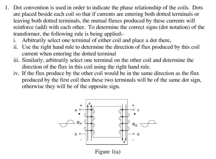
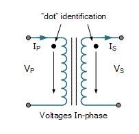
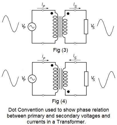
To eliminate any confusion in the phase relation between primary and secondary voltage and current, a dot convention has been adopted for transformer schematic diagrams. Dots are placed on the top of primary and secondary terminals as shown in fig (3) and (4)
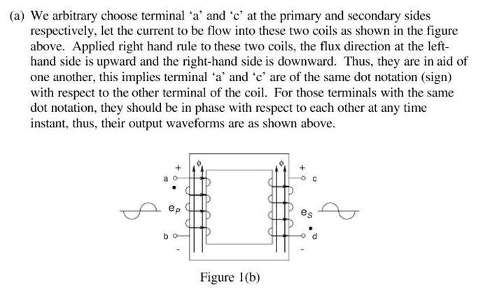
In fig (3), we see that dots are placed at the top in both primary and secondary terminals. It shows that the primary and secondary current and voltages are in phase. Moreover, the primary and secondary voltages (VP and VS) have similar sine wave, also the primary and secondary (IP and IS) currents are same in direction.
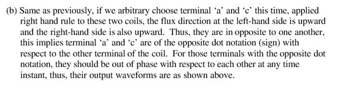
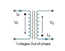
The story is opposite in fig (4). We can see that one dot is positioned at the top in primary terminal and the other one (dot) is placed at bottom of secondary terminal. It shows that the primary and secondary current and voltages are 180° out of phase. In addition, the primary and secondary voltages (VP and VS) sine waves are opposite to each other. Also the primary and secondary currents (IPand IS) are opposite in direction.
Please note: This article is in reference to: electricaltechnology.org
If Voltage and Currents are not in phase
For example, in an Autotransformer, we have Voltage in one polarity and Current in another. I want to quote Wikipedia:
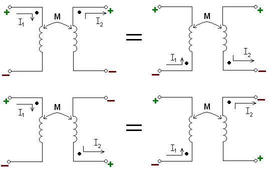
If two mutually coupled inductors are in series, the dot convention can be used in the same manner as in the case of autotransformers. Relative polarity in autotransformer drawings is usually quite obvious by physical placement of the windings in circuit drawings.
Autotransformers
So we see that the Mutual Inductance is the determining factor but layout is important to take into account.
Chris
EDIT:
Re-reading the Thread, I see my wording is not very good! I tried to point out the Dot Notation but in doing so, have made what I see now as confusing statements!
I apologise for this everyone!
Conventional Electromagnetic Induction is always Equal and Opposite minus Losses!
This is Fact and cant be disputed!
To make sense of this Thread, One must apply the Right Hand Grip Rule to the Coils.