My Friends,
I am seeing a renewed push of powerful Disinformation! Its very powerful, some with reasonably large budgets showing very stupid Experiments to get others excited and hopeful for new results on old BS that never ever once produced any results. Its a very powerful new push!
Yes, the Liars, Cheats, BS Artists and general Trolls, you know: The Spooks and Freaks, are out, trying to have one last push before they completely fail!
I will tell you: Very soon we will have:
In terms of energy, they talk about up a box with a new technology, and it gets warm, but not hot, and you get a different size box, to power a building, or to power a car, so I don't know what the box is.
It sounds like a battery.
No I don't think so I think it's a new technology but I didn't know enough when I first heard this to ask them to describe it in greater detail.
The Muppets that had control of the globe, now losing control very fast, will not be able to stop this.
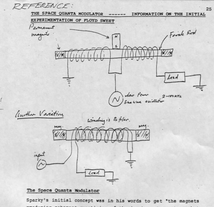
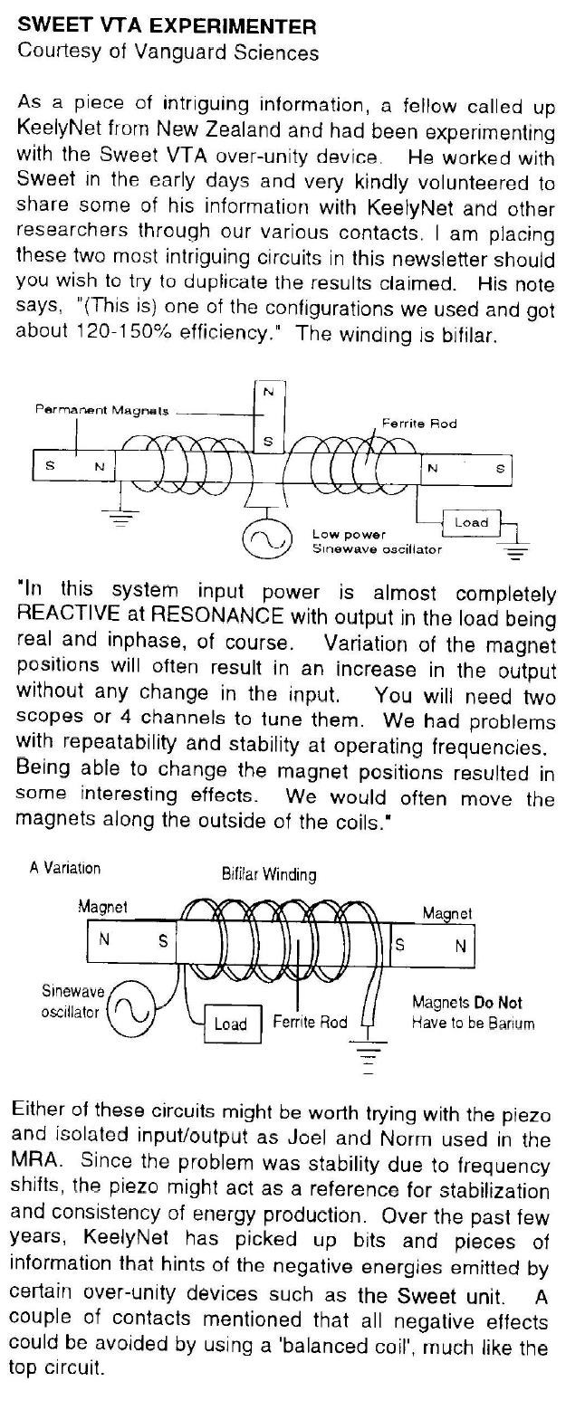
Let's not forget what Floyd Sweet said to Mike Wattson:
He also says "Magnets are spaced 2" apart in traction mode The excitation coil is inside the and is bifilar and wound to cause space stress in the magnets. The excitation is very weak but apparently moves the traction flux. The kernal flux of the conditioned magnet is cancelled out at least 1" from the pole faces, the central airgap flux is made to appear and disappear in step with the space stress caused by the excitation coil."
Now we know, from experiment, that this statement was very accurate!
FYI: Traction Flux:
In classical physics and early electrical engineering literature (late 19th and early 20th centuries), the term "traction flux" (often referred to interchangeably with tractive flux) designates the specific lines of magnetic force responsible for generating a physical pulling, gripping, or attractive mechanical force across an air gap.
Depending on the specific sub-discipline of vintage engineering—whether dealing with electromagnets (relays, brakes, lifting magnets) or electric rail transit (electric traction motors)—the term carried distinct contextual meanings.
1. The Electromagnetism Context: Tractive Force Flux
In early texts on electromagnetic mechanisms (such as Silvanus P. Thompson’s seminal 1891 work, The Electromagnet and Electromagnetic Mechanism), traction flux refers to the magnetic field lines that cross directly from a magnetic pole face into a moving iron armature to pull them together.
The Mathematical Foundation
According to classical electromagnetic theory, when magnetic flux crosses an air gap between two parallel ferromagnetic surfaces, it creates a mechanical pull known as tractive force. This is calculated using a simplification of the Maxwell stress tensor:
$$F = \frac{B^2 A}{2\mu_0}$$Where:
$F$ is the mechanical pulling force (tractive effort) in Newtons.
$B$ is the traction flux density (flux per unit area crossing the gap) in Teslas.
$A$ is the cross-sectional area of the pole faces in square meters.
$\mu_0$ is the permeability of free space ($4\pi \times 10^{-7} \text{ H/m}$).
Because the force scales with the square of the flux density ($B^2$), early designers focused heavily on concentrating the traction flux into the smallest possible area to maximize the gripping or pulling capability of clutches, relays, and telegraph sounders.
2. The Electric Heavy Machinery Context: "Traction" Motor Flux
In the literature surrounding early streetcars, locomotives, and electric trolleys—collectively known as electric traction systems—the phrase took on a slightly altered, system-level meaning.
In a traction motor (typically a series-wound DC motor), the "traction flux" refers to the primary field flux generated by the stator field coils to produce high starting torque.
Why Traction Flux Was Managed Differently:
Massive Starting Torque: A locomotive requires immense force to move from a dead stop. In a series motor, the input current flows through both the armature and the field coils. At startup, low speed means low back-EMF and high current, causing the "traction flux" in the stator to surge instantly to its maximum capability, creating the necessary mechanical pull.
The Air Gap Constraint: In standard stationary industrial motors, the air gap between the stator and rotor can be microscopic. In early rail traction motors, the air gap had to be physically wider to withstand the heavy mechanical vibrations, bumps, and debris of rail travel. Consequently, engineers had to drive significantly more magnetomotive force (MMF) through the coils just to maintain a stable traction flux across that wider physical gap.
3. Historical Distinctions from Other Flux Types
To keep their calculations clean, early electrical engineers carefully segregated traction flux from other structural magnetic fields in the machine:
Leakage Flux: This is flux that spills out into the surrounding air or loops back early through the housing without crossing the active air gap. Because it fails to pass through the intended armature or rotor path, it performs zero mechanical work and reduces efficiency.
Armature Reaction Flux: As a motor turns, the current flowing through the rotor creates its own magnetic field. In old texts, this field was noted for distorting and opposing the clean "traction flux" coming from the stator, which could lead to heavy sparking at the carbon brushes if not properly neutralized.
And for Kernel Flux:
In late 19th and early 20th-century electrical literature—particularly texts translated from or heavily influenced by Germanic engineering nomenclature (where Kern means core and Kernfluss means core flux)—the solid or laminated iron center of a transformer, inductor, or dynamo was frequently referred to as the "kernel" or "kern."
Consequently, kernel flux (often written as kernel-flux and conceptually synonymous with mutual core flux) refers to the primary body of magnetic lines of force that remains entirely confined within the high-permeability iron path to link the electrical circuits.
1. Definition and Practical Purpose
Unlike traction flux, which is deliberately forced across an open air gap to execute physical mechanical work (like pulling an armature or turning a rotor), kernel flux is intended to remain strictly inside the closed ferromagnetic loop. Its purpose is purely electrical: to maximize mutual induction between independent coils according to Faraday's Law of Induction.
2. The Physics and Mathematical Framework
In early machine design, engineers calculated the magnitude of the kernel flux ($\Phi_{kernel}$) using Hopkinson's Law (the magnetic circuit equivalent of Ohm's Law):
$$\Phi_{kernel} = \frac{\mathcal{F}}{\mathcal{R}_{core}} = \frac{N \cdot I}{\frac{l}{\mu A}}$$Where:
$\mathcal{F}$ is the magnetomotive force produced by the coil turns ($N$) and current ($I$).
$\mathcal{R}_{core}$ is the magnetic reluctance of the iron kernel.
$l$ is the mean geometric path length of the iron core loop.
$\mu$ is the absolute magnetic permeability of the core material.
$A$ is the cross-sectional area of the iron core.
Because the magnetic permeability ($\mu$) of engineered transformer iron is thousands of times greater than that of the surrounding air, the magnetic lines of force naturally pool inside the iron structure, creating a highly dense, concentrated core of flux.
3. Historical Distinction from Leakage Flux
In classical literature by pioneers such as Charles Proteus Steinmetz and Gisbert Kapp, heavy emphasis was placed on mathematically separating total structural flux into two strictly defined components:
The Kernel Flux: The mutual portion of the flux that stays perfectly within the boundaries of the iron core and successfully cuts through both the primary and secondary windings to transfer power.
The Leakage Flux: The stray portion of the flux that escapes the boundary of the iron "kernel" and completes its circuit through the surrounding air space.
In early transformer design, maximizing the ratio of kernel flux to leakage flux was the ultimate goal. Excess leakage flux meant poor voltage regulation, unwanted inductive reactance, and phase displacement.
4. Constraints: Magnetic Saturation
Old engineering manuals focused heavily on the limits of the iron kernel. If the excitation current ($I$) was driven too high, the iron would hit a point of magnetic saturation.
Once saturated, the domain boundaries within the iron kernel could no longer align any further. Any additional flux generated could no longer be contained within the core matrix, causing it to force its way into the surrounding air as leakage flux. This crippled the efficiency of the transformer and generated severe thermal stress due to localized hysteresis losses.
While the historical term refers to the primary magnetic fields within an iron core, the name has been revived in modern neurotechnology; you can watch CONTROL YOUR MIND with BCI | Kernel's Non-Invasive Brain Computer Interface to see how modern magnetometers track tiny magnetic fluxes produced by neural activity.
So, I ask you all to be very careful what you see and hear by some Muppets! They actively try to get you all excited by a bunch of shiny nothings! Don't be a Kia and get Dazzled by Shiny Nothings!
Best Wishes,
Chris