

My Friends,
What happens when you Generate a Voltage in POCOne?
Knowing POCOne's Voltage is determined by Faradays Law: E.M.F = -N ΔΦB / Δt, and measuring, we can see the Open Circuit Voltage on POCOne that is Generated.
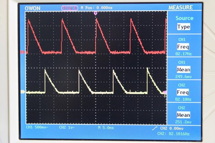
At this point, if we short POCOne we will have a Low Impedance Circuit, the maximum Current will flow, and we will have an instance where the Magnetic Field will be held High, the Magnetic Field will be restricted to Change, however because we have a NON-Super Conducting Coil, the Magnetic Field will dissipate and we will see:
The Fall of Current, which is proportional to the Magnetic Field, is a Linear Function and we see:
Ref: Some Coils Buck and Some Coils Don't
Depending on What You Do, and Where You Do It, you can make the Coils do some pretty amazing things! A Video, our friend Zanzal shared sometime back now:
Here is a pretty good explanation:
I wish YouTube user: "debunkified" took this to the next step. However, he did do a good job!
The Bucking Effect is what gives you Power Output, while not effecting your Input! Or at least, very little reverse effect, back onto your Input, because the Bucking of POCOne and POCTwo, as we know, the Magnetic Field Superposition: POCOneMMF + POCTwoMMF = Zero! In other words, the Magnetic Fields Cancel out, and the Rotor see's no Reverse Effects, or your Primary Coil see's no reverse effect.
Know and understand: A Voltage is "Generated" and a Current is "Pumped"!
Voltage is the Separation of Charge by a Changing Magnetic Field.
Current is Charge forced or broken away from the Atom, under High Stress conditions, pumped via an external Magnetic Field.
When can a Voltage NOT be Generated?
Once the Magnetic Field is restricted from Movement, a Voltage stops being Generated. For example, the Common Mode Choke, filters out Transients, because it Un-Generates Voltages.
The Common Mode Choke uses the Common Core and Coils to filter out all Noise within the Design Spec:


The Inductance can be configured to Un-Generate Noise and transients.
These Videos are Fantastic:
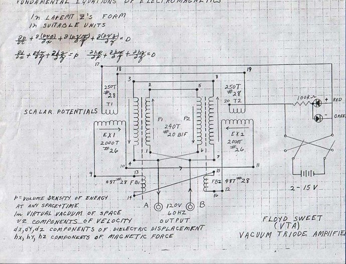
Remembering Gabriel Kron was Floyd Sweets mentor! Please note:
In the context of Gabriel Kron's "Tensor Analysis of Networks," a balun (balanced-to-unbalanced transformer) is a device that allows for the interface between balanced and unbalanced transmission lines without disturbing the impedance of either line. Kron's work explores the application of tensor analysis to network theory, and baluns are examples of network components that are analyzed within this framework. Specifically, an off-chip transformer can act as a balun, improving filter-Q and achieving impedance matching, which are concepts relevant to Kron's network analysis, according to a research paper on Universal Frequency-Domain Analysis of N-Path Networks.
Balun - Balanced-to-Unbalanced Transformer
A balanced-to-unbalanced transformer, also known as a balun, is a type of transformer that converts a balanced signal to an unbalanced signal or vice versa. It's a crucial component for interfacing devices that use different wiring schemes, such as balanced audio lines and unbalanced consumer electronics.
This Video is very good:
![]()

Bits on Baluns – Part 3
By: Peter McNeil
06/21/2018
Basic Baluns
The type of balun used in microwave RF designs depends on the bandwidth required, the operating frequency, and the physical architecture of the design. As differential power dividers, baluns can be transformers, capacitively and/or magnetically coupled transmission lines, hybrid couplers, or used in a combination of power divider and inverter. Baluns are used in many applications from creating transitions between single ended and differential signals and in canceling mode noise and signals. The baluns most important property is in power balance and phase balance.
The flux coupled balun transformer is the most common type of balun which is basically two separate wires wound around a magnetic core with one side of the primary winding grounded thus creating an unbalanced condition on the primary side and a balanced condition on the secondary side. The secondary side can have an arbitrary ratio of turns to the primary side creating the arbitrary impedance ratio. The flux coupled balun transformer will induce an AC voltage in the secondary of n times the voltage in the primary, while the current will be n times smaller than in the primary, giving an output impedance of n2 as stated above, where n is the ratio of turns in the secondary to turns in the primary.
Wire wound flux coupled transformers often have a center tap in the secondary winding with a ground – connecting this point to the ground of the secondary system can improve the balance of the output.
For example, a flux coupled transformer is best suited to frequencies below 1 GHz but often experiences coupling loss at higher frequencies; magnetic materials have a large loss tangent which leads to high signal losses at microwave frequencies. Thus, the capacitive coupled transmission line balun, most often with a bifilar transmission line wrapped around a magnetic core, solves the high frequency problem with the low frequency magnetic coupling and the high frequency capacitive coupling as seen in the Guanella balun.
A balun that is often used in microwave applications is the Marchand balun. The video, Types of Spiral Baluns describes spiral baluns, Interwound, Symmetrical, and Marchand, and the design and simulation of GaAs MMIC planar spiral balun.
Classical Transformer Balun
In classical transformers, or isolation transformers, there are two separate windings of wire coils around the transformer core which can be empty or air, a magnetically neutral material like porcelain, or a magnetic conductor, or soft iron. The primary winding receives the input signal and the secondary winding sends out the converted signal. For ideal transformers, although the ratio of voltage to current will change in exact proportion to the square of the winding ratio, the power, measured in watts, remains identical.
Advantage: electrically separate windings for input and output allow these baluns to connect circuits whose ground-level voltages are subject to ground loops or are electrically incompatible.
Autotransformer or Voltage Balun
An autotransformer balun has one coil or two or more coils that have an electrical connection also wound on a ferrite rod or toroid. A single winding must have at least one extra electrical connection, or tap point, between the ends of the winding. The current sent into the balun through one pair of connections acts as a primary coil and magnetizes the core.
Advantage: unlike transformer-type baluns, an autotransformer balun provides a path for DC current to ground from every terminal.
Transmission-line Transformer or Choke Balun
Sometimes called a current balun, this type of balun ensures equal current on both sides of its output, but not necessarily equal voltage. The currents inside coax are equal and opposite so the magnetic fields are also equal, opposite, and mostly cancel. When a transformer balun is combined with the transmission-line transformer balun, the resulting device has very wideband operation. The Guanella transmission-line transformer is often combined with a balun to act as an impedance matching transformer.
Advantage: the choke balun prevents extra current flowing back along the transmission through inductive impedance.
Delay-line Balun
Using connected transmission lines of specific lengths with no transformer element, these delay-line baluns are usually built for narrow frequency ranges where the connected transmission line lengths are a multiple of a quarter wavelength of the intended frequency in the transmission line medium as seen in a coaxial connection to a balanced antenna.
Advantage: causes 180° phase shift and provides a balanced input.
Self-resonance Balun
Transformers made of real materials have a small capacitance between the primary and secondary windings, as well as between individual loops in any single winding, forming unwanted self-capacitance or parasitic capacitance. When the electrical reactance of the self-inductance and self-capacitance in the balun are equal and opposite, resonance occurs. A balun of any design type operates poorly at frequencies at or above its resonance. Design considerations for baluns are for the purpose of making the resonant frequency as far above the operating frequency as possible. As frequencies rise, the impedance of the parasitic capacitance drops until it’s magnitude equals that of the ideal inductance known as Self Resonant Frequency (SRF).
The inductance acts like an inductor up to its SRF then the impedance becomes very high and the inductor can be used as a choke to attenuate signals near the SRF.
To learn more about Pasternack’s line of baluns, visit: https://www.pasternack.com/nsearch.aspx?Category=Baluns&sort=y&view_type=grid


I am guessing you are starting to see the similarities:
Gabriel Kron's Negative Resistor
Gabriel Kron later took a job with the Lincoln Electric Company in Cleveland and presented his first paper in 1930. In 1934 He joined General Electric and worked there in various departments, all concerned with applied engineering.
It was there that he talked about the "Negative Resistor". His notes about the Negative Resistor went largely unnoticed. While working for G.E. in the 1930's Kron used Negative Resistance circuits in equipment he designed for the U.S. navy's "Network Analyser". Absolute Negative Resistance is - according to the laws of nature - not possible - as it means "free energy".
The Guanella Balun
A Guanella balun, also known as a current balun or 1:4 current balun, is designed to transform impedance from a balanced, high-impedance side to an unbalanced, low-impedance side. The characteristic impedance of the transmission line used in the Guanella balun is ideally half of the impedance on the balanced side. For example, for a 75-ohm to 300-ohm transformation, the characteristic impedance would be 150 ohms.
The Guanella balun, a type of transmission line transformer, converts unbalanced signals to balanced ones, and vice versa. It uses coiled transmission lines to achieve this, often incorporating magnetic cores for improved bandwidth and efficiency. The core concept involves creating a phase shift between the signals on the transmission lines, resulting in balanced currents at the output.
Transmission Lines:
Guanella baluns typically employ two transmission lines, often bifilar coils, with identical lengths.
Phase Shift:
The transmission lines create a phase shift between the signals, ideally resulting in signals at the output with the same amplitude but opposite polarity.
Impedance Transformation:
The balun can also act as an impedance transformer, converting impedances between balanced and unbalanced systems.
Magnetic Cores:
Coiling the transmission lines on a magnetic core, like a toroid or rod, can enhance bandwidth and reduce the length of the transmission lines, according to Minikits and All About Circuits.
1:1 and 4:1 Baluns:
Common types include 1:1 and 4:1 baluns, where the ratios indicate the impedance transformation.
Mathematical Principles:
Impedance Transformation:
The impedance transformation ratio in a 4:1 Guanella balun is 4:1. For a 1:1 balun, the impedance remains the same.
Phase Shift:
The phase shift between the signals on the two transmission lines is crucial for creating balanced currents.
Transmission Line Characteristics:
The characteristic impedance (Z0) of the transmission line is an important parameter in balun design.
Impedance Matching:
The impedance of the balun should be matched to the impedance of the balanced and unbalanced lines to minimize reflections.
Applications:
- Antenna Systems: Guanella baluns are widely used in antenna systems, particularly to interface between coaxial cables (unbalanced) and balanced antenna systems (dipoles, Yagis).
- Matching Impedances: They are also used to match impedances between different systems.
- Reducing Common-Mode Currents: Baluns can help mitigate the effects of common-mode currents on antenna feedlines.
In summary, the Guanella balun is a versatile device that facilitates impedance matching and signal conversion between balanced and unbalanced systems. Its design relies on the principles of transmission line behavior, phase shifts, and impedance transformation.
A Balun is an acronym for Balanced Unbalanced = Balun.
Unbalanced System:
An unbalanced system is an electrical circuit or transmission line where the signal is referenced to a single ground or common conductor, with one conductor carrying the signal and the other serving as a return path (e.g., coaxial cable). This configuration is susceptible to common-mode noise and interference due to unequal impedances or currents in the conductors.
Balanced System:
A balanced system is an electrical circuit or transmission line where two conductors carry equal and opposite signals relative to a common reference, typically with no direct connection to ground (e.g., twisted pair). This setup minimizes noise and interference by canceling common-mode signals, as the differential signals maintain symmetry.
REMEMBER: Ohms Law, Current I = Voltage V / Resistance R, so, you MUST have a Voltage in POCOne, and the Higher the Voltage, the Higher the Current, through the same Resistance!
Best Wishes,
Chris


