My Friends,
I want to tell you: You are perfectly able to achieve Free Energy through these machines we have given you!
I will help you achieve this task!
Its real, it works, we have shown all of the world how this works and why this works!
Voltage, Current, where 6.241509 x 10¹⁸ Electrons, Stationary is One Volt, or One Coulomb if stored, or if moving at a rate of One Second, is One Ampere.
What makes Charge Move?
A Changing Magnetic Field!
We have shown you, Magnetic Fields arranged in an Asymmetrical arrangement, can give you a lot more Energy Output than you have to Input! Its only when you have a Symmetrical arrangement of Magnetic Fields, that you are bound to Below Unity Machines, because: Output = Input - Losses, = Below Unity!
@30:13 minutes, you will see:

This is very simple, if you read this post carefully, you can very easily see the commonsense, and the logic here to why this works! You can easily do this, you can have your own Free Energy Machine! You can see right there on the bench, something that Science has tried to tell you for hundreds of years, cant be done! We have done it, we are doing it!
I have shown you, what the other forums never ever showed:
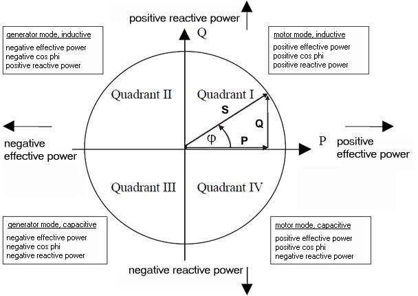
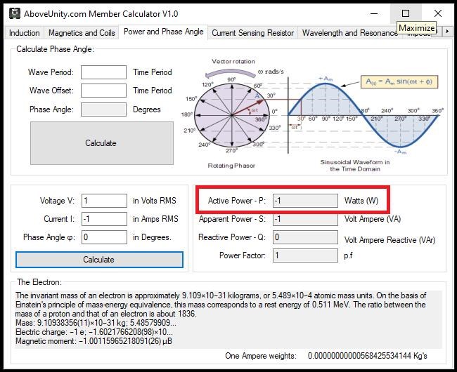
We have covered before, the fact that the Input Coil sends Power Back to your Input! This is directly related to the Argand Diagram:
We can have Positive Voltage and Positive Current for Positive Power!
Inversely, we can have Positive Voltage and Negative Current, for Negative Power!
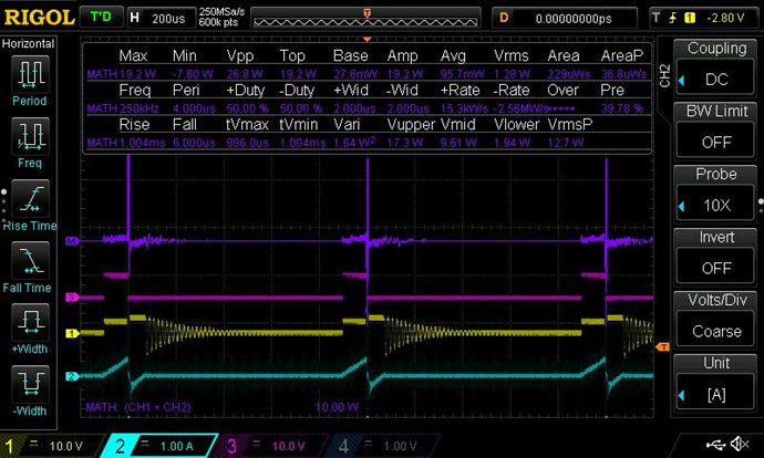
Here is an example:
Where:
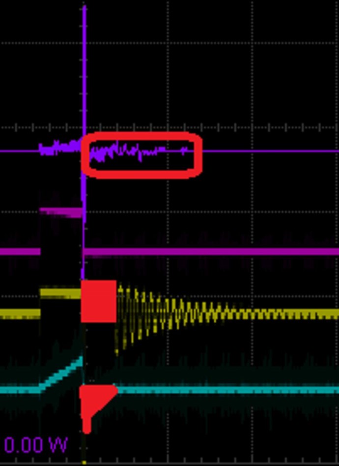
- Purple Trace is the Math, showing Positive and Negative Power.
- Pink Trace is the Gate Signal to the Mosfet.
- Yellow is the Input Voltage.
- Teal Trace is the Input Current, both Positive and Negative.
I must apologise, I have better examples of this, but do not wish to confuse everyone. This example is sufficient to show what I am talking about.
Again, marked in Red, Positive Voltage and Negative Current, you have Negative Power. Not Negative Energy, Negative Power, I hope people do not confuse this as I believe people have in the past.
I hope this helps others when doing experiments, knowing what to look for is very important!
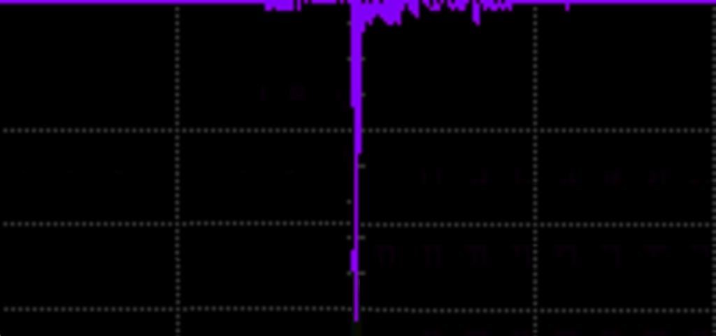
Remember: This is the very reason you can NOT Use RMS Measurements on the Input! See Measurements Thread and see the above Figures:
- Average: 95.7 mW
- RMS: 1.28 W
A Huge error here! 1.28 - 0.095 = 1.185 Watts. 13.474 times!RMS is totally Wrong! Remember, your Zero Graticule Line is very important:
- above: Positive
- below: Negative
Its worth noting, there is 1.28 Watts in the System. An analogy, inaccurate as it stands, is, Power Delivered to the Coil might be in the order of 1.28 Watts. Then the Coil returns 1.28 - 0.095 = 1.185 Watts back to the Power Supply. So the Total Power used is only: 0.095 Watts. Power Returned, is not Power Used!
This is Reactive Power Conditions, except V and I are in apparent phase. We have 1.28 Watts of Work Done for the Cost of 0.095 Watts. I hope this makes sense? Please understand, the example is not giving accurate Power In and Out, only using figure seen in this Analogy for simplicity.
I believe, 1.28 - 0.095 / 2 = 0.5925, is the In and Out power. I am sure others here, perhaps YoElMiCrO, Jagau, Vidura, or someone can correct me here?
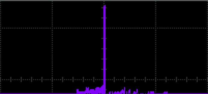
Meaning, the Power in Purple Above the Zero Graticule Line:
Is more than the Math in Purple Below the Zero Graticule line:
By: 0.095 Watts.
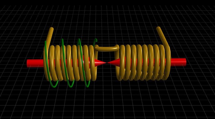
Ref: The Input Coil
No one, ever, has shown you this effect, they could not, because they simply just did not know what they were doing, they were Plants, in a pot, there to hold you all back and stop you from discovering anything important! Well, what I have shown you above is astounding and it very important to understand!
I have been here, doing this for a very long time now, my Character has been attacked at every level by Trolls, but they have never once proven me wrong, because they cant! My Track Record speaks for itself, many have achieved what I have given them! Many have done the impossible, because its actually very easy and relatively cheap to achieve!
In 1831, Michael Faraday was always supposed to give you the complete picture, but for some 197 Years, it still isn't clear! Well, my web pages show you the complete picture, and why we have seen, through out history, so many people show machines that just cant be explained:
These demonstrations exist because they were real, but hidden from you! Stupid people acting like idiots, spreading fake nonsense about these machines, because they cant stop, and logically work them out. Far to many people with Ultra Egos and a God Complex, when in fact the complete opposite is true! It was satan worshippers keeping you from this!
Floyd Sweet was my Hero, and I have studied him for a long time!
We have resurrected the VTA Technology, and we have shown where so many lied and spread fake nonsense about it!
Truly: This Works and You can do it!
Best Wishes,
Chris