Chris
posted this
04 October 2019
- Last edited 05 October 2019
My Friends,
YoElMiCrO and Vidura's work, to understand Fighter's work, is very important!
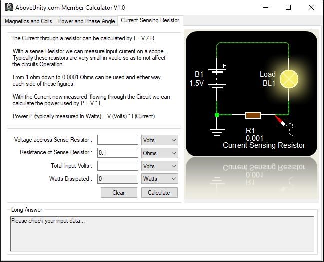
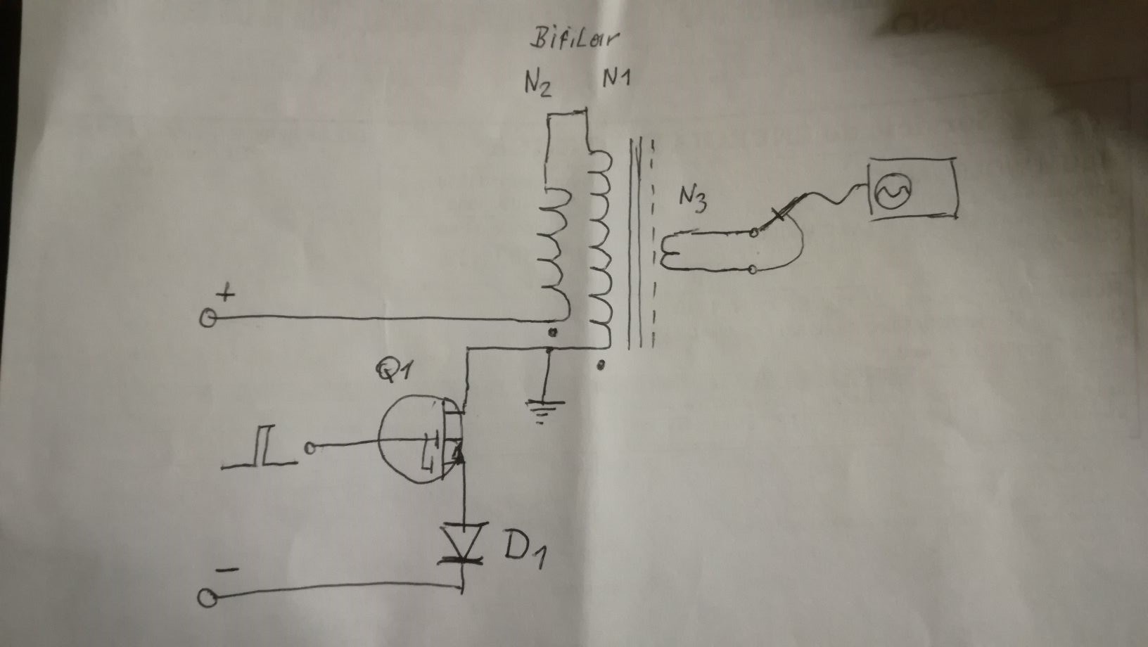
Lets take the following Experiment:
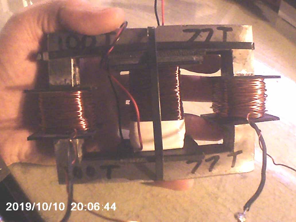
A Single loop of wire, the length of a single loop is: 111mm and we have 100 loops the same length.
Our 100 loops at 111mm each is equal to N1.
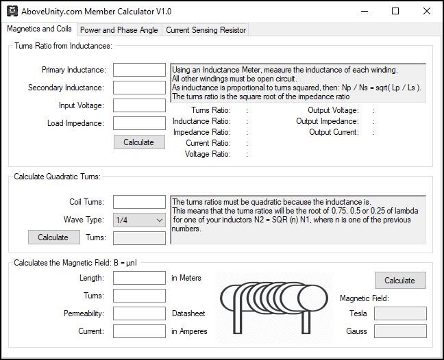
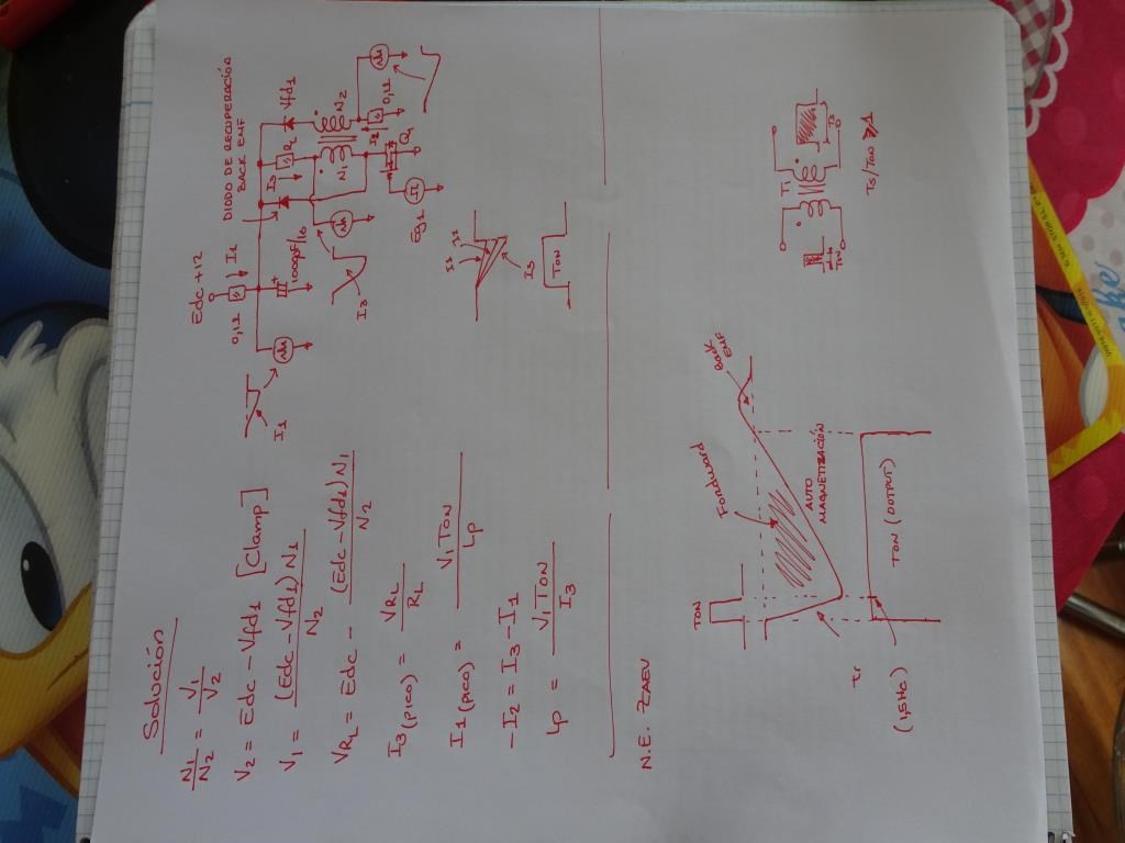
Our equation:
N2 = SQR (n) N1
Ref: YoElMiCrO
So, calculating: N2 = sqrt(0.25) * 100 = 50 loops at 111mm each.
Now comparing:
- N1 = 111 x 100 = 11,100mm.
- N2 = 111 x 50 = 5,550mm.
For Half Wave: N2 = sqrt(0.5) * 100 = 70.71 loops at 111mm each.
- N2 = 111 x 70.71 = 7,848.81mm.
For Three Quarter Wave: N2 = sqrt(0.75) * 100 = 86.6 loops at 111mm each.
- N2 = 111 x 86.6 = 9,612.6mm.
Now, if we look at the length of the wire:
- 11,100 / 2 = 5,550mm = 1/4 wave, which is what we calculated for N2.
Respectively, we can get:
- 11,100 / 1.414 = 7,848 = 1/2 wave.
- 11,100 / 1.154 = 9,612 = 3/4 wave.
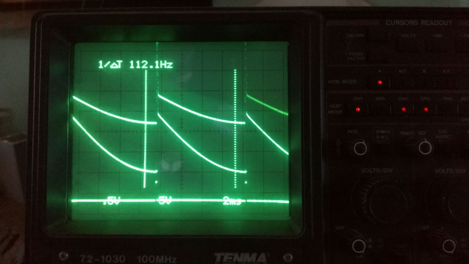
The Frequency ( f ) = 27.00 MHz
The Speed of Light ( c ) = 299,792,458 meters per second
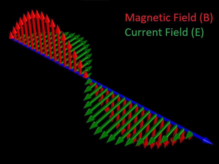
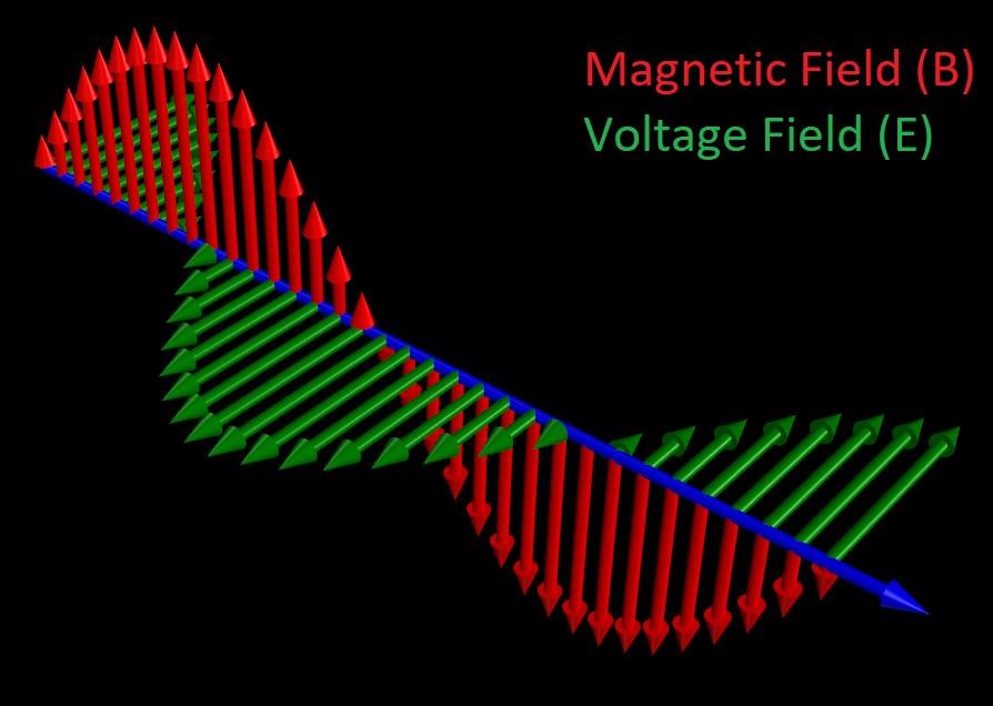
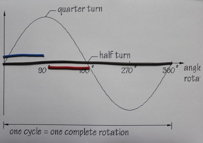
We know, for an Antenna, a Half Wave is the optimum Wavelength to transfer Electromagnetic Energy, this is: λ / 2
Where
- Lambda ( λ ) = the Wavelength at Resonance.
Which means:
- Lambda ( λ ) = Speed of Light ( c ) / Frequency ( f ).
- Lambda ( λ ) = 299,792,458 / 27,000,000 = 11,103mm
- 11,103mm ≅ N1
- 11,103mm / 2 = 5,551mm
- 5,551mm ≅ N2 calculated above ( N2 = 111 x 50 = 5,550mm )
Remember this:
This, in combination with our Antenna Theory threads, here and here, with the thread here and here, means we have a lot of very special logic to study!
The Coils become Resonant at the Half Wavelength, which is calculated by the Quarter Wavelength of 0.25. This is using the Inductance, but means the Wire length of N2 is half that of the N1 as seen in the above Experiment, which is Lambda ( λ ) / 2.
However, please remember, this is only one way, many ways exist to get to the same goal! We are specifically referring to Fighters work in this thread.
Chris


.jpg?width=690&upscale=false)
.jpg?width=690&upscale=false)