My Friends,
In DC Switched Machines, the Input Coil plays a very important role.
Two things are achieved:
- Creates a Magnetic Field in the Device.
- Induces an E.M.F, or a Voltage on the terminals of the Output Coils.
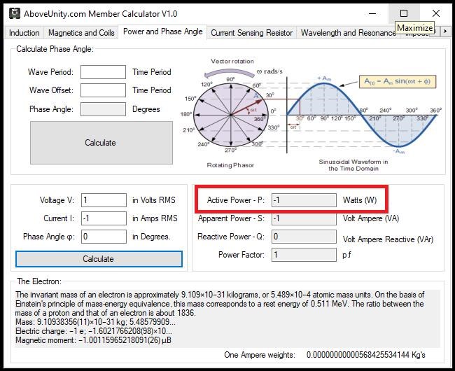
There is another way to think about this, the Magnetic A Vector Potential is an Electric Field with Curl:
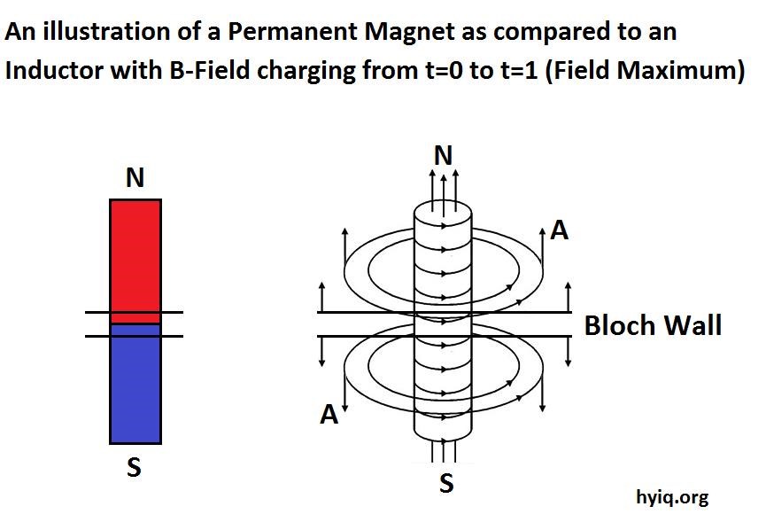
One could say that it is the Magnetic A Vector Potential that is disturbed:
When you find the AB effect is indeed invoked, then you can adjust the magnitude of the E-fields produced in the A-potential reservoir by dA/dt. That means you adjust the rise time and decay time of the input pulses. Also play around with frequency (each unit has its own "sweet spot").
Ref: http://www.cheniere.org/correspondence/061603.htm
We have heard this many times before, but one example comes to mind:
I'm not allowed to give any more hints than that, except to point out that wire size and numbers of windings are also variables you must investigate rather thoroughly. They do have great effect on the COP.
Ref: http://www.cheniere.org/correspondence/061603.htm
If one were to do a full analysis on all the devices over the years, and all the Input Coils, one would find very few turns and normally a heavier gauge wire.
E.G:
- Don Smith used: 4 turns of perhaps No# 12 Insulated Wire.
- Akula used: 7 Turns of perhaps No# 18 Insulated Wire.
- And so on...
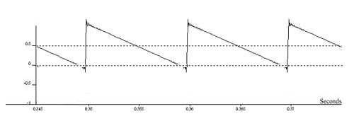
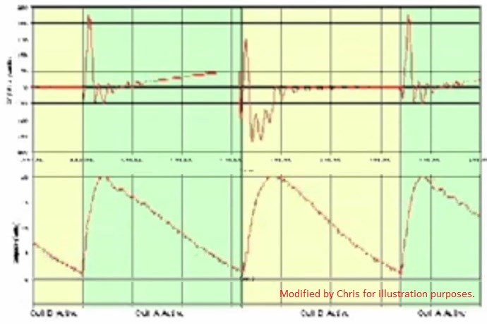
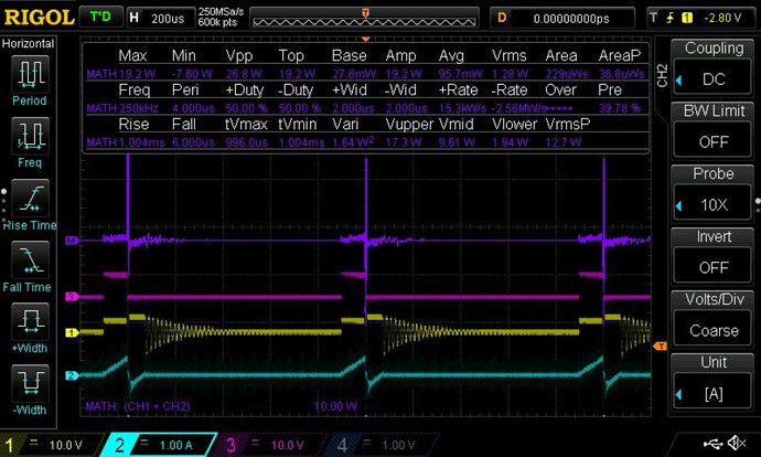
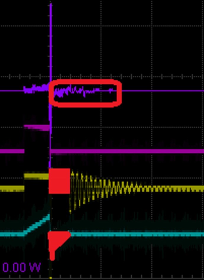
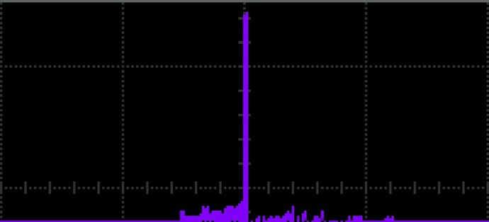
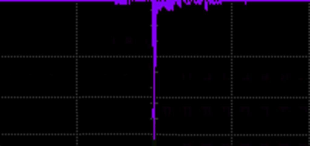
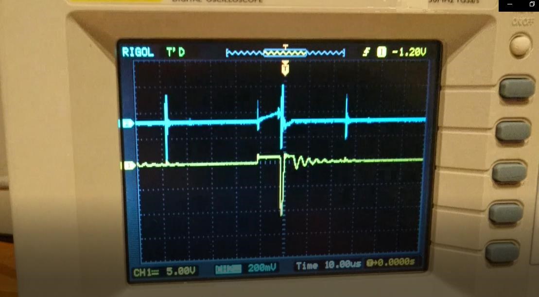
We also see this in our detailed study of the Asynchronous Re-Gauging, which we have proven to be valid on many devices:

As you can see, the Regauge Region is very much shorter in Time than the Work Region.
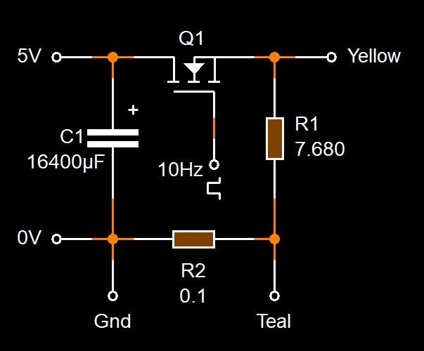
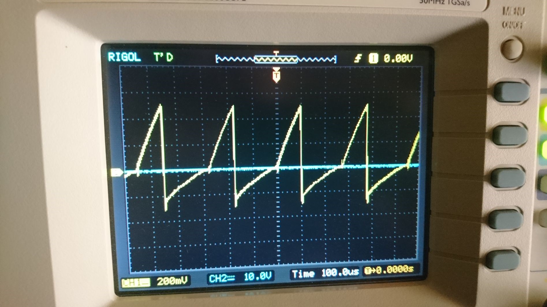
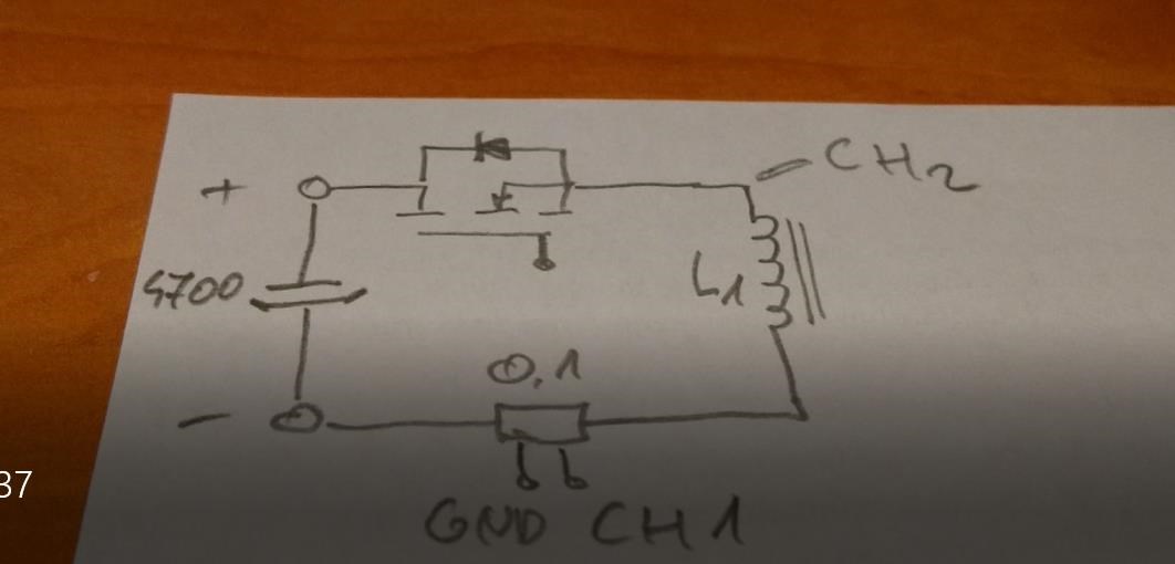
An Input coil must be able to do its job quickly and efficiently, and the Time to do its job can be calculated by using:
T = L / R
The Time Rate of Change is reduced by reducing the Inductance ( L ) and Resistance ( R ), shorter thicker wire means faster Rise Time. This makes your Regauge Region faster. This also means your Switching Time must be shorter, say 10% Duty Cycle.
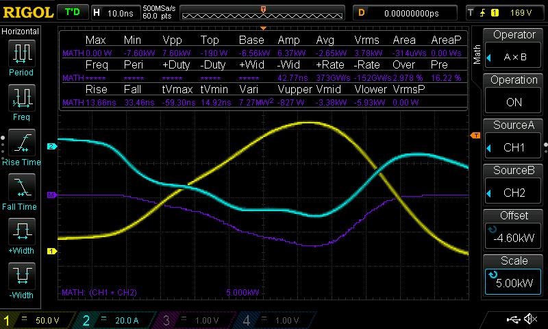
Note: We have seen, history has shown us many examples, one must find the optimum point where the Rise time has done enough to allow the Partnered Output Coils to do enough Work, in other words: "Generate" enough Electrical Energy, to cover losses and enough to Power a Load.
One such example of this is the tuning required in the following video:
By turning on the English subtitles you will get somewhat of an explanation of the Timing required.
Another example is Bradley's RT, by attaching the Fan, slowing the Rotor and the Pulses, the machine was below unity. We must invoke the Partnered Output Coils interaction so as to:
Below is a bad google translation in a text file.
Related Threads:
Chris