Chris's Replication of Lari Man's Объект 013Б

  • Topic Is Sticky
  • 4.4K Views
  • Last Post 2 weeks ago
Chris posted this 16 October 2018

Hi my friends,

I have not replicated this one yet! So, I am making a dedicated thread for this replication. I am going to build the Lari Man's Lantern,, which was called the: Объект 013Б.

I copied his video and postings from realstrannick.com:


I have all the original files.


Another video, looks to be a Google Live Stream recording:


   Chris


Light Up the Darkness!

Order By: Standard | Newest | Votes
Vidura posted this 30 September 2019

You forgot the square root Fighter, A mistake that so many have made. In the example I put the winding ratio that GR saw on the video, for half wavelength (0.5) the SQR is 0.707, this multiplied by N1 (41T) = 28.99= 29 turns for the second coil section. Regards Vidura

getreal156 posted this 30 September 2019

Got it. Thanks Vidura !

Fighter posted this 30 September 2019

You forgot the square root Fighter, A mistake that so many have made. In the example I put the winding ratio that GR saw on the video, for half wavelength (0.5) the SQR is 0.707, this multiplied by N1 (41T) = 28.99= 29 turns for the second coil section. Regards Vidura

Yes, that's correct. My mistake, I was focused more on describing the steps of calculations than on calculations themselves.

So these are the calculations corrected:

N1 = N2 * SQRT(0.25) = N2 * 0.5

or

N1 = N2 * SQRT(0.5) = N2 * 0.707

or

N1 = N2 * SQRT(0.75) = N2 * 0.866

So let's suppose you want your smaller coil to have 10 turns, so we have N1 = 10.

Then we have:

for 0.25 wavelength: 10 = N2 * 0.5 so N2 = 10 / 0.5 = 20 turns for bigger coil

for 0.5 wavelength: 10 = N2 * 0.707 so N2 = 10 / 0.707 = 14.14 turns for bigger coil

for 0.75 wavelength: 10 = N2 * 0.866 so N2 = 10 / 0.866 = 11.54 turns for bigger coil

Chris posted this 30 September 2019

My Friends,

Tariel Kapanadze gave us a gift:


As did Don Smith:


Many others also, we have only covered a few.

What's the most basic thing we see?

We see Turn for Turn, a Magnetic Cancelation Factor:

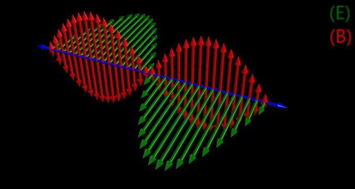
If the directions of the two signals are such that opposite H-fields cancel and E-fields add, an apparently steady E-field will be created. The energy density of the fields remain as calculated above, but the value of the E-field will double from E / 2 to E.

Ref: Floyd Sparky Sweet


Which means this:


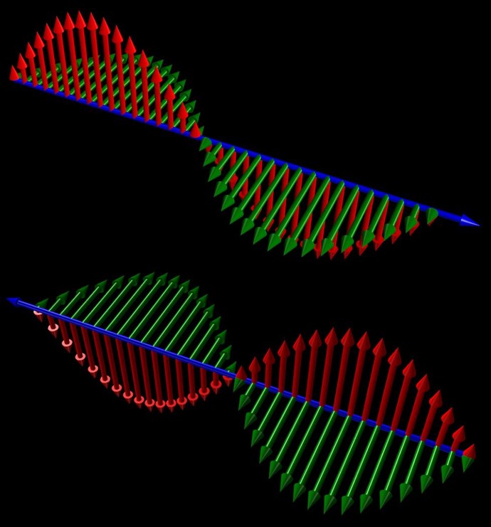
NOTE: The Blue arrows indicate the Direction of Travel. Red is Magnetic Field, Green is Current, where the E Field is normally depicted as Voltage, I have shown it as Current.

Note the Amplitude of the Green, or Current.

Now combining the two Waves, traveling in opposite Direction:


We see a: Standing Wave.

Of course, as you stated, Andrey Melnichenko also used the same concepts: pointed out here.


We have a treasure trove of Data:

The principle of superposition states that;

"In order to calculate the resultant intensity of superimposed fields, each field must be dealt with individually as though the other were not present".


The resultant is obtained by vector addition of each field considered singularly.

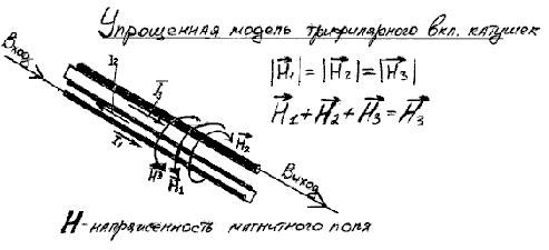
Consider for a moment the construction of the triode which includes the bifilar coils located within the fields of the two conditioned magnets.

When the current in one half of the conductors in the coils (i.e., one of the bifilar elements in each coil) of the device is moving up, both the current and the magnetic field follow the right-hand rule.

The resultant motional E-field would be vertical to both and inwardly directed.

At the same time the current in the other half of the conductors in the coils is moving down and both the current and magnetic field follow the right-hand rule.

The resulting motional E-field is again vertical to both and inwardly directed.

Thus, the resultant field intensity is double the intensity attributable to either one of the set of coil conductors taken singularly. Expressed mathematically;

E = ( B x V ) + ( -B x -V ) = 2( B x V ) 

where:

   E = Electric Field Intensity

   B = Magnetic Field Intensity

   V = Electron Drift Velocity 

The first term ( B x V ) in the equation represents the flow of the magnetic field when the electrons are moving in one direction, while the second term ( -B x -V ) defines the flow of the magnetic field when the electrons are moving in the other direction.

These measurements indicate that field intensity is directly proportional to the square of the current required by the load placed on the device.

This is due to its proportional relationship with the virtual value of the magnetic field which theory states is proportional to the current. Electrometer readings were always close to parabolic, thus indicating that the source was of infinite capacity.

Ref: Floyd Sparky Sweet - Nothing is Something.


Floyd Sweet talks about Canceling H and c, it was very obvious, that this was the primary goal of Floyd Sweet!

to cancel out H and c...

  • H = Magnetic Field
  • c = Speed of Light.


So, yes, you're right GR! Well done!

   Chris


P.S: Other Forums copy our work, finding obscure names to try to hide the very same technology, they try, but they still copy our work, it is so obvious its not funny. We are Light Years ahead of the other forums!
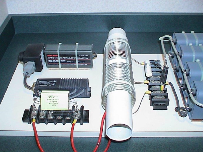
getreal156 posted this 01 October 2019

Hi guys,

Question about the workings on the MC34063 chip

Yesterday I started with bread boarding my first replication of the Lari-man device. Very efficient circuit ... and weird results.
The MC34063 chip normally is powered by straight DC. On the other hand, the coils are pulsed and thus the feedback to the chip is also pulsed.
My question is, how can this chip still function properly ? Should the input voltage be regulated in such a way that the pulses of the feedback to the chip stay between the lower and upper threshold voltage limits of the chip?

I was about to do some tests with pulsing the input of the chip to see how it would behave, but I thought I could ask here also.
My first thoughts would be to rectify the voltage before feeding it back to the chip. 

Does any one has experience with this? 


Fighter posted this 01 October 2019

I have the same situation with ZPM. As it's getting power from my DC source in pulses with high frequency, the signal on my DC source's output is also made of high-frequency pulses, it's not DC anymore. I don't see a solution about how this can be solved, I think as long as our devices are getting power in high-frequency pulses we will always have non-DC on the inputs. But maybe I'm wrong, maybe there is a way and I'm not aware of it...

Chris posted this 01 October 2019

My question is, how can this chip still function properly ? Should the input voltage be regulated in such a way that the pulses of the feedback to the chip stay between the lower and upper threshold voltage limits of the chip?


Hey GR,

Worth having a read of the Datasheet on this one: MC34063 Datasheet and Theory and Application is especially good!

8.1 Overview

The MC33063A and MC34063A devices are easy-to-use ICs containing all the primary circuitry needed for building simple DC-DC converters. These devices primarily consist of an internal temperature-compensated reference, a comparator, an oscillator, a PWM controller with active current limiting, a driver, and a high-current output switch. Thus, the devices require minimal external components to build converters in the boost, buck, and inverting topologies.

The MC33063A device is characterized for operation from –40°C to 85°C, while the MC34063A device is characterized for operation from 0°C to 70°C.


If the threshold voltage is breached, the chip goes into a sort of starve mode and the PWM is changed.

The error amplifier monitors the output voltage level, compares it to the reference and generates a linear control signal that varies between two extremes, saturation and cutoff. This signal is used to vary the resistance of the series−pass element in a corrective fashion in order to maintain a constant output voltage under varying input voltage and output load conditions.


Its a very smart little chip for what it is.

Much to read, I will not add to it.

   Chris

skywatcher posted this 18 December 2019

Is anyone still working on this replication ?

This device (if it really works) would be the ideal demonstrator for overunity.

But i wonder why no one (at least outside Russia) was able to replicate it in the last 4 years.


I also wonder about the function of the switch. This switch is present in all 'Akula-style' devices i have seen. But this switch would not be necessary to demonstrate the function of the device. So why is it included in every device ?

The second point i wonder about (only present in the LariMan device) is the strange PCB layout.

What is the purpose of the big copper patches ?  Do they have any function ?  Why didn't he use normal tracks ?

skywatcher posted this 23 December 2019

Now i have all the parts needed for this circuit.

The ferrite core is a 42mm N27 core without air gap (EPCOS/TDK B66325G). I was not able to get big enough C-cores but i think any core should work, and if it's not exactly the same as in the original circuit you have to tune it anyway.

I made the PCB as similar as possible to the original layout, with the difference that i flipped it so i can solder the components on the surface, that's much more convenient than drilling holes, and it's also better for doing measurements.

In the next days i will build up the circuit, and look what it's doing...  smile

skywatcher posted this 23 December 2019

Chris posted this 23 December 2019

Nice work Skywatcher!

I gave up with my replication. I felt that this could work with enough time, but its tricky!

I hope you have more success than I did!

   Chris

Chris posted this 30 July 2020

Hi Guys,

After reading through this post I noticed that most here have missed the most critical detail of this device.
The secondary is not 1 coil !
It is in fact 2 coils that are wound in opposite direction and connected in series. 

After unwinding 28 turns clock wise, he fiddles with a small piece of tape that holds the wire bend in place and then he continues with unwinding  41 turns counter clockwise (If I counted well). 
Take a very close look how he unwinds the coil in this video. He is trying disguise the winding scheme by turning and fiddeling with the ferrite core.

(starting at 25 : 35). 

The good news is that we have seen this type of winding many times before. I recognized the winding scheme from Earl Koenig and Andrey Melnichenko. Paul Raymond Jensen also describes the same type of winding scheme.
They are all doing exactly the same thing !

I bet Akula is using this winding scheme also

Ref: GR's Post Here.


My Friends,

Just wondering, has anyone verified GetReal156's experiment here?

My Experiment: Chris's Non-Inductive Coils Experiment shows how the Coils need to Interact. This Interaction can be done with two separate Coils as I have shown, but also can be done as GetReal suggested, a very good suggestion!

There is a specific Resonance that must be obtained. We all know this, so this is a bit harder to obtain in this situation. This was pointed out by Vidura:

You forgot the square root Fighter, A mistake that so many have made. In the example I put the winding ratio that GR saw on the video, for half wavelength (0.5) the SQR is 0.707, this multiplied by N1 (41T) = 28.99= 29 turns for the second coil section. Regards Vidura

Ref: Vidura's post Here.


Of course we know Tariel Kapanadze wound his coils this way. I do want to say, this is not the only way.

28 / 42 = 66.66% of the turns are non inductive. Don't forget, we need the Voltage up, Current I = Voltage V  / Resistance R. The Voltage out of the L2 Coil must be sufficient to charge Run Capacitors.

Best wishes, stay safe and well My Friends,

   Chris

Gucio_81 posted this 2 weeks ago

Hello everyone.
I've been back into playing with coils for some time thanks to this forum, thank you Chris 
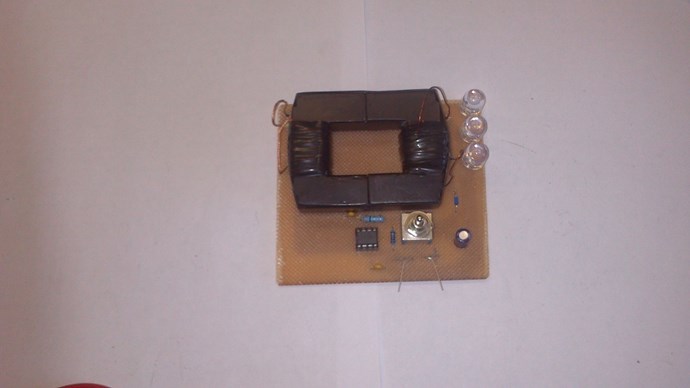
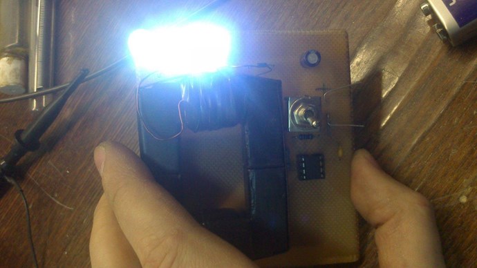
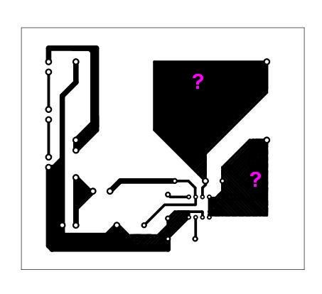
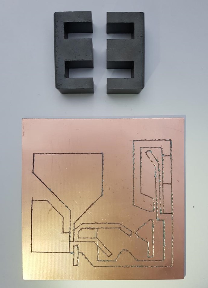
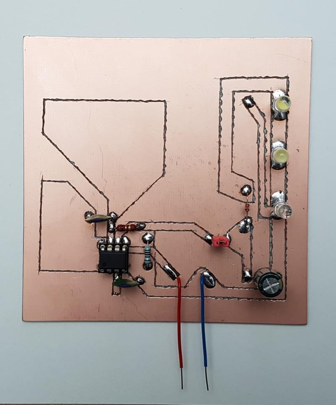
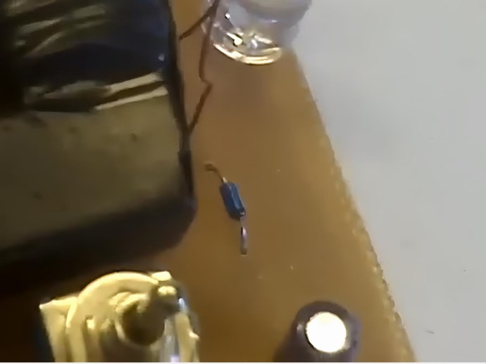
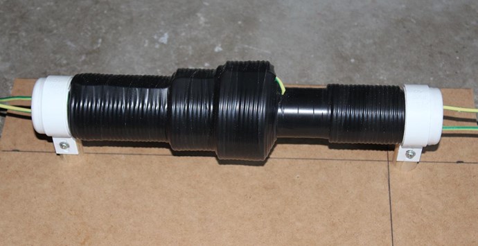
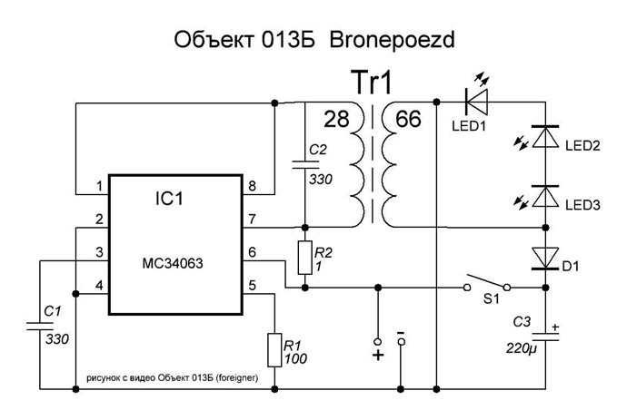
. I built a replica of "Lari Man's Object 013Б", of course with poor results 
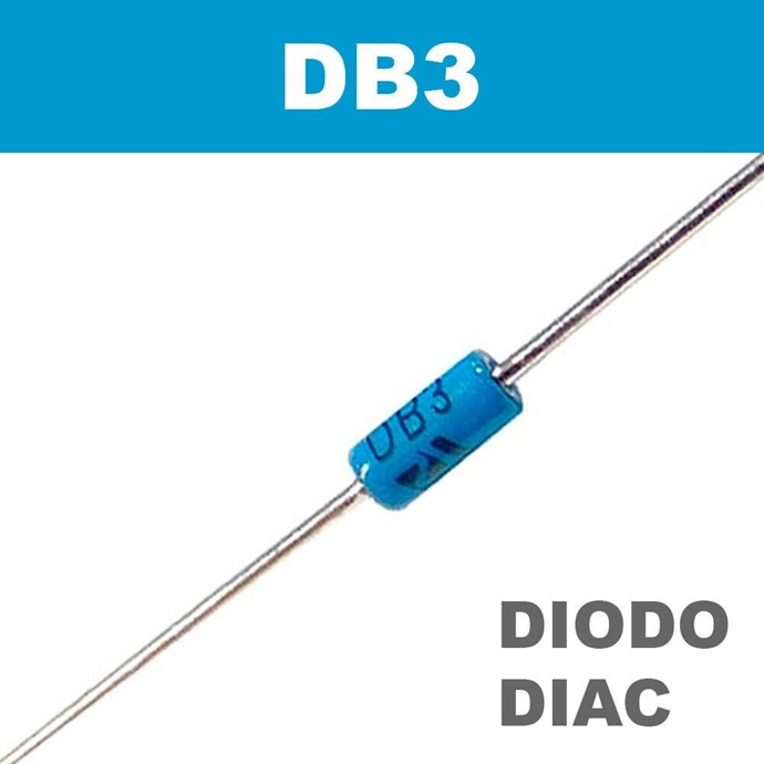
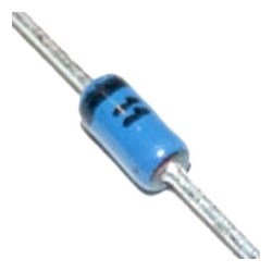
. I test different coils and windings. I have some ideas to test, for example a bifilar coil on the secondary winding of the transformer, as suggested by "getreal156". I also wanted to refer to Chris's suggestion that it could be a diac or another diode, which he pointed out. I watched the video of the working "Lari Man's" replica several times from this link


and decided to take a closer look at this diode. Nowadays, we have strong AI video processing tools and I decided to improve something.
I took one frame from the movie.
I corrected and improved as best I could


In my opinion, it is also not a DIAC diode but a 11V ZENER diode (the voltage visible in the video is 10.86V).


Looking through the diagram, it would make sense because the zener diode is connected to the circuit in a prohibitive manner. Soon I will post photos from my observations and fun with the "Lari Man's Object 013B" replica.
Regards.

We're Light Years Ahead!
Members Online:
What is a Scalar:

In physics, scalars are physical quantities that are unaffected by changes to a vector space basis. Scalars are often accompanied by units of measurement, as in "10 cm". Examples of scalar quantities are mass, distance, charge, volume, time, speed, and the magnitude of physical vectors in general.

You need to forget the Non-Sense that some spout with out knowing the actual Definition of the word Scalar! Some people talk absolute Bull Sh*t!

The pressure P in the formula P = pgh, pgh is a scalar that tells you the amount of this squashing force per unit area in a fluid.

A Scalar, having both direction and magnitude, can be anything! The Magnetic Field, a Charge moving, yet some Numb Nuts think it means Magic Science!

Message from God:

Hello my children. This is Yahweh, the one true Lord. You have found creation's secret. Now share it peacefully with the world.

Ref: Message from God written inside the Human Genome

God be in my head, and in my thinking.

God be in my eyes, and in my looking.

God be in my mouth, and in my speaking.

Oh, God be in my heart, and in my understanding.

Your Support:

More than anything else, your contributions to this forum are most important! We are trying to actively get all visitors involved, but we do only have a few main contributors, which are very much appreciated! If you would like to see more pages with more detailed experiments and answers, perhaps a contribution of another type maybe possible:

PayPal De-Platformed me!

They REFUSE to tell me why!

We now use Wise!

Donate
Use E-Mail: Chris at aboveunity.com

The content I am sharing is not only unique, but is changing the world as we know it! Please Support Us!

Thank You So Much!

Weeks High Earners:
The great Nikola Tesla:

Ere many generations pass, our machinery will be driven by a power obtainable at any point of the universe. This idea is not novel. Men have been led to it long ago by instinct or reason. It has been expressed in many ways, and in many places, in the history of old and new. We find it in the delightful myth of Antheus, who drives power from the earth; we find it among the subtle speculations of one of your splendid mathematicians, and in many hints and statements of thinkers of the present time. Throughout space there is energy. Is this energy static or kinetic? If static, our hopes are in vain; if kinetic - and this we know it is for certain - then it is a mere question of time when men will succeed in attaching their machinery to the very wheelwork of nature.

Experiments With Alternate Currents Of High Potential And High Frequency (February 1892).

Close