Clarification on a few things

  • 561 Views
  • Last Post 15 hours ago
drachonite posted this 15 July 2026

I have read the bucking coil PDF and watched the videos. From this knowledge I have build various prototypes with all but one working properly.
Coil A & B is wound as partner coils with the right hand rule and 0.4mm enamel coated copper wire(Rated at 5Amp), 100 turn each. The pulse coil is wound in the exact same way as Coil A with a layer of insulation tape in between, 20 turns for a 5:1 ratio mentioned. There is 2 separate pieces of 10mm ferrite core spaced about 3-4mm apart in the center. I'm using Coil A as my output coil and Coil B as my resonator coil.

Running the pulse coil from my signal generator @ 12V square wave 5% duty cycle 200mA(Current limited), with the device optimal at 170 KHz, I'm getting 19.1V and 17.2V under load, which is a 41% gain over my input voltage. The maximum current I can draw is 530mA which gives me the 2V voltage drop. With a rectifier parallel over the load I get 17.1V DC out, with the load removed I get the 19V out. I would have thought that I can at least get the 5amp the wire is rated for???
The frequency of coil B is 980KHz and the voltage around 190V but there is no current though if you connect one side of a bulb to the end and ground the other end the bulb lights up. 

The pulsing circuit settled at a natural resonant frequency of 81Khz with the same setup as above, 12V square wave 5% pulse. The current draw is 4.2 amp which suggest there is a fairly strong magnetic field plus the voltage of coil A is 1.8KV. If I short coil B my output voltage drops by half and the current draw from the PSU drops from 4.2 amp to 2.1 amp.

Adding resonant capacitors to coil A and B has no effect. My next step is to pass the 2KV output to a 2kw step down transformer to 220V and then rectify to get around 300V DC.
I want to aim for a unit that can produce 4kw DC constantly.

Here are my questions.
How do I get to the 10X amps that the PDF mentioned?
What is the coloration between the core watt rating and the wire amp rating?
Would the step down be limited to the 2kw of the step down transformer?
Would using 0.9mm wire rated at 10amp make a difference?
Would I need to ferrite with a higher KW rating?

Pulser

Coil Setup

Images liked above as my file manager just comes up blank.

  • Liked by
  • Chris
  • Drasko
Order By: Standard | Newest | Votes
Chris posted this 17 July 2026

Hello and Welcome Drachonite!

I firmly believe one needs to understand Voltage and Current fairly well to be able to build Energy Machines. Voltage is Charge Separation and Current is Pumped from Source, where Source is Outer Orbital Electrons in the Valence Band.


Voltage

Voltage is the total number or Charge, Elementary Charge, but I prefer Free Electrons, that have been separated, on the Conductor, where one Terminal has a greater proportion of Free Electrons compared to the other Terminal. This is called the Potential Difference in Charge. One Volt is equivalent to: 6.241509 x 10¹⁸ Electrons.
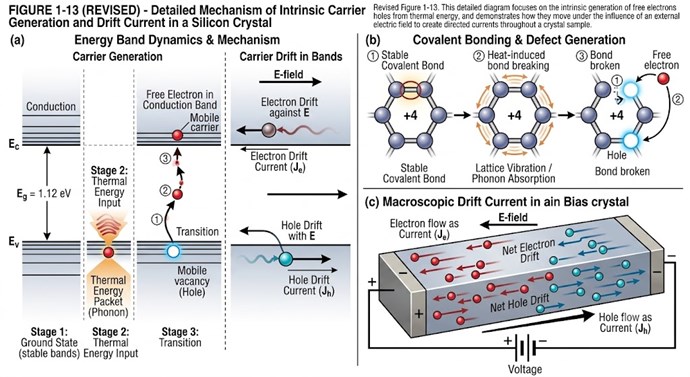
 

This means, if we were to have a Potential Difference of One Volt on a Battery, one Terminal has more Free Electrons, compared to the other Terminal, by 6.241509 x 10¹⁸ Electrons.

What causes Electrons to move to this Terminal?


Elementary Charge

Elementary Charge is just the Electron that is in a High Energy State.
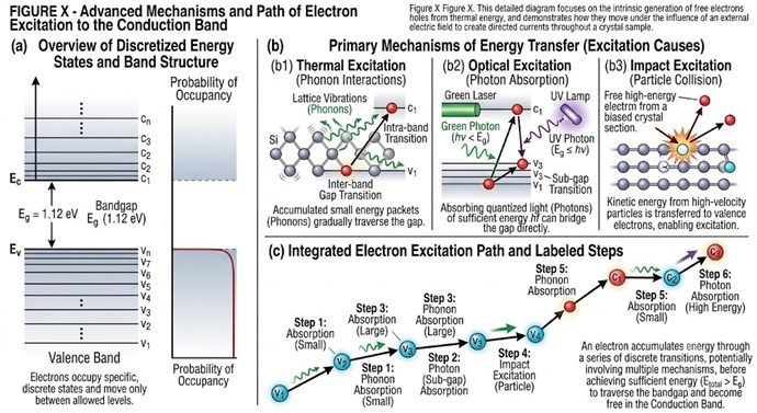
 

The Electron, if it is exposed to certain conditions, it will move up in Energy States. See the above image. The Electron eventually moves right up to the Outer Orbital, and the Electron then has the potential to be knocked out into the Conduction Band.

The Electron, because it has Charge, it has a Magnetic Moment, which, when combined with its intrinsic angular momentum (spin), dictates its behavior in quantum systems and electromagnetic fields.

To expand on the physics: an electron has both an electric charge and an intrinsic property called "spin" (a type of quantum angular momentum). In classical physics, a spinning charge generates a magnetic field. While quantum mechanics tells us the electron isn't literally spinning like a top, this combination of charge and spin still gives the electron its intrinsic magnetic dipole moment. This tiny magnetic field is exactly what makes things like MRI machines work, and it is the fundamental reason why materials like iron can be magnetized.
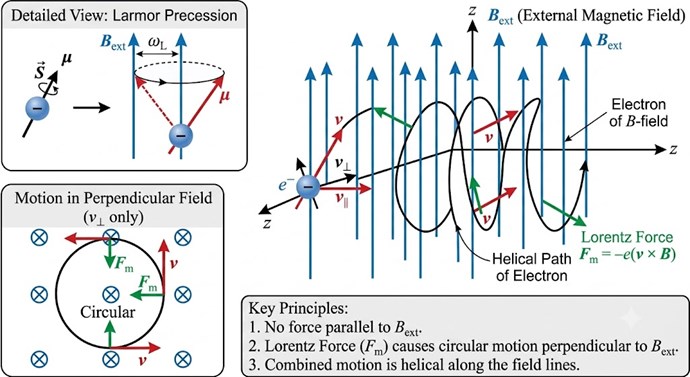
 

Of course, under the right conditions, we can Accelerate the Electron down the Wire:


Current

The Rate of Flow is what defines Current. If we want to measure One Ampere, we measure: 6.241509 x 10¹⁸ Electrons past point P1 in one second.

The Total Amperes measured boils down to the total number of Free Electrons that can move through the Conductance Band.
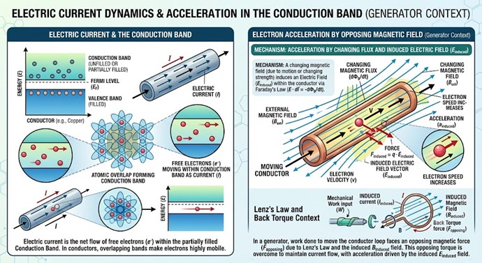
 

Only when you turn on the switch and the globe lights, can you then, observe the effects of Lenz's Law, the Opposition of Magnetic Fields, the Opposition of Currents, which in turn IS the Drag on the Rotor Shaft, which is the reason Input Power goes up under load, and the reason for the second law, the conservation of energy laws. Lenz's Law is a given and everyone has seen it in one form or another.

Understanding Current is a very important requirement! If we truly understand Current, we can see areas that open doors for Smart Techniques to introduce Asymmetrical Electromagnetic Induction!


Asymmetrical Electromagnetic Induction

Asymmetrical Electromagnetic Induction is the exact opposite to the well known Electromagnetic Induction we all know very well today! 

Example of Symmetrical Electromagnetic Induction: The Conventional Transformer is an entirely Symmetrical Device; an Input Coil, an Output Coil, Symmetrical Forces between Input and Output Coil, this is why no one can use a Symmetrical Device to get an Energy Gain, because they are inherently a Closed, fundamentally restricted devices where: Output = Input - Losses


$$ P_{out} = P_{in} - P_{loss} $$

Here is a breakdown of the variables:

  • $P_{out}$ represents the output power.

  • $P_{in}$ represents the input power.

  • $P_{loss}$ represents the energy lost to heat, friction, or other inefficiencies.
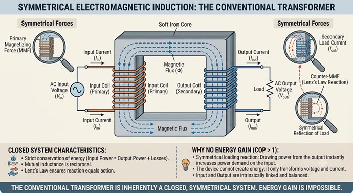
 

If I say to you: "If you load this Transformer more and more, so the Output Current increases: Is, the Input Current: Ip must go up to compensate." do you see the very tight correlation to Lenz's Law and the Currents in Opposition?

This is where: "Partnered Output Coils" come in and why Asymmetrical Electromagnetic Induction change the Stage we work on and why we can get a Gain in Power.

If I propose to you: "What if, your Transformer did not Oppose your Input Coil directly, and the same Opposition was still present in the system, but it was redirected to another Coil, instead of your Input Coil?"


What this means

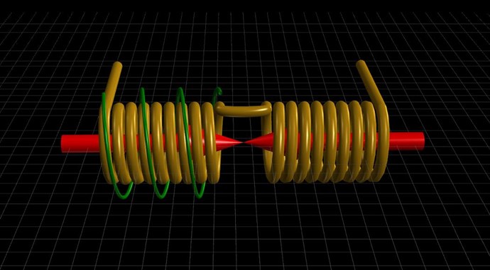
In any System, by shifting the Units of Force onto a different Source, we can still do the same total work, but the Force in the System is not directed back on us! We shift the Force and redirect it to another Source. This is what "Partnered Output Coils" achieves. The trick is, one needs to get the Voltage up, we need to trick the "Partnered Output Coils" into both seeing a specific Voltage, then we can make the "Partnered Output Coils" do ALL or the Work for us!
 

Answering your Questions

To answer your questions directly, once you understand the above very simple physics, is quite easy.

Here are my questions.
How do I get to the 10X amps that the PDF mentioned?
What is the coloration between the core watt rating and the wire amp rating?
Would the step down be limited to the 2kw of the step down transformer?
Would using 0.9mm wire rated at 10amp make a difference?
Would I need to ferrite with a higher KW rating?


  1. Amperes are Pumped from Source by Opposing Magnetic Fields, but the Equation: I = V / R holds, so you must have a Voltage and Resistance of known values to get Current I.
  2. This question has answers through out my Forums pages. Please study the material provided.
  3. Working this high in Voltage is not recommended, I have never recommended High Voltage, I recommend starting with 2 or 3 volts, slowly move up from there if needed.
  4. Yes, but this is a way later on question and is not important at the start.
  5. No, Ferrite may be an option for High Frequency. Its not a requirement, use any core you can, any coils you can. 


I have a few guides here in these pages, and in the pdf, I do provide basic starting recommendations, perhaps a review may be helpful. I suggest Low Voltage, Small Coils, and a few simple components, then, replicate Experiments I have already shared, learn the very basic stuff I have shared, then you will understand the above, and then you will see why the Opposing Magnetic Fields are important and why Partnered Output Coils give Humanity a new Physics, Asymmetrical Electromagnetic Induction, the next step after Symmetrical Electromagnetic Induction!

Best Wishes,

   Chris

electrondiger posted this 18 July 2026

drachonite i read zour post and i am hapy you put in the work

I did it some years ago even rewriten bz hadn every post on this forum, then some fight broke lose....

Zou know i wodu realy liek to see soem resoult of this techings.  I mean if i do the work where this stuf leds to. Did enbodz repliakte every test on this forum adn get some meningful rezults or stuf get hiden last last tiem one guy suskeded and yust keep it to him self.


I dont visit this forum as ofen i did in the past, it is sad,... 

... but i like chris what he try to do...

i don tknow,... i stil ahve quadratron adn transformers here on the tabel for 4 years,...


is enbody sukseded to build osme device with some desent output here or it is al in tear 2 or hiden for persona gain,.. i yust wonder,...

do this do that,... years go by adn you wonder is even viable.


buz the way, is tehre eny posibility to check if two wawes ad on eletric field,.. with some device test or probe or somthing,..


Have a nice day.


drachonite posted this 3 weeks ago

Thanks for all the info. For beginners I would suggest building the rotary generator rather than the solid state as it's more forgiving.

I used what I had lying around and built a mechanical and a solid state version. The solid state is working but there is still some tuning to do so that it works like I want.

Attached is a video of the generator I have working and mentioned all the important things..

drachonite posted this 3 weeks ago

Check out the generator I just posted and you'll see it working. Once you understand the foundation of bucking coils building a working device is fairly simple. 

The generator above took about 2 weeks but the bigger one I'm building will take much less time. The most time of the build is winding the coils and placing them in the core. the rest is fairly simple.

That one is now powering my inverter via the solar input. Let me know if the video is helpful. 

Chris posted this 3 weeks ago

Hey Drachonite,

This is a fantastic post! Thank You for posting Sir! Very impressive to see such a wonderful implementation here! The Motor that ran freely, its the exact same.


The really sad thing is, YouTube promotes videos like this:

https://www.youtube.com/shorts/2SDWKuxP2fM


On YouTube, when you search: "Free Energy Electric Motor", and they get Videos with, in excess of One Million Views, its how the powers that try to be, hold you all to Ransome, by filling your heads with complete nonsense! This is Propagandised to the absolute max! YouTube floods your search with total propaganda! Its so obvious, ppl get paid to spread maximum nonsense!

You have successfully implemented the concept, so well done!

Best Wishes,

   Chris
drachonite posted this 3 weeks ago

Hi Chris,

There is a lot of misinformation out there unfortunately and people don't really want to put in the work. It took me just 4 weeks from starting to learn to having several working devices, plus it can easily scale to megawatts.

My catamaran is fully electric so I will be powering the electric motors with this tech, my electro-gravitic research and other tech. Everything can be powered by this tech which removes any dependency on the corporations. 

If you need a hand with anything just ask.


FringeIdeas posted this 3 weeks ago

Hey drachonite,

Thank you for the post, good video. I think I might be a but confused though. So a question, and I promise I'm not trying to be difficult.

In the video you say the magnets are all N facing out. And you say the coils on opposing sides are bucking. But wouldn't that mean that, for example, the top coil is N facing down, facing the N from the magnet.. and the bottom opposite coil is N facing up, facing the N from it's magnet? That sounds symmetrical.

But then also in the video you say

So if you are putting south on the outside (speaking about the rotor magnets), then you need to just change the way that you connect the two bucking coils together. So that all of your magnetic field flows in the same direction. And then the way you connect it in bucking is to then force one of the coils in the opposite direction.

So while in bucking mode, are the two opposite coils, for example N facing N polarity, or S-N-S-N through the two coils? And what mechanism are you using to force the opposite direction of one of the coils?

Again, I'm just a bit confused, not trying to be difficult.


Unrelated, you said you printed the rotor? Did you use magnetic material or is that standard ABS or something? Just interested, I do a bit of 3d printing myself. I've seen a few guys on youtube try magnetic material but at that time it was not yet past hobby standards. Interesting though for sure.

Thanks again!

Marcel

drachonite posted this 2 weeks ago

This video explains it simply so it clear up any confusion.

The rotor in printed in PLA with 3 layer walls and 25% cubic infill.

FringeIdeas posted this 6 days ago

Hey drachonite!

First, sorry about the super delayed response, life has been super chaotic lately. And thank you for the follow up video, that was super awesome you put that together!

Bare with me while I still play confused though 😄

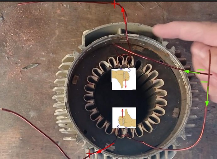
From what I have learned from this forum is bucking coils (both being output coils) should be configured in a way that they see each other as an input coil. This effectively keeps the back emf, reflected impedance, whatever you want to call it, away from the real input coil. This requires asymmetry in most cases, e.g. a odd number of coils. From your latest video, this is what I'm understanding...


Right hand rule shown. As the magnet approaches the coils we get a induced voltage shown by the red + signs. Assuming there is a load nature then runs a current, shown by the red and green directional arrows. Negative voltage shown by the green - signs. The input in this scenario is the motion of the magnets. So far this appears to me to be standard elecromagnetic induction. No asymmetrical bucking. The only abnormal thing I see is that the wires that are tied together are both negative. And the wires that go out to the to the output are both positive. To me this would mean a net current flow of zero. 

Now, that being said, a net current flow of zero would probably mean no drag on the rotor, input. Which is good. But at the same time there is now output. Unless maybe some resonance condition is being met?

At the same time, there is the magnetic coupling of the coils through the body of the stator. Maybe there is some cancellation of magnetic flux going on there, isolating it from the magnets?

This is something I'm going to have to play with. Because talk and speculation doesn't pay the bills.. bench time is what matters. And I will at some point, I just need to find the time. Like I said I've been super busy. The past few months have been a real life trial for me.

Side note for @Chris. Still waking up, and going to bed, thinking about this stuff. Sorry for my absence. I do enjoy sharing what I'm learning, and I'll get back to it hopefully sooner than later.

Thanks again drachonite!

Marcel

  • Liked by
  • Drasko
  • Chris
drachonite posted this 3 days ago

Your top green arrow need to point to the right then it should make sense.

Remember the 1 + -1 + 1 = 1 and the asymmetry as there are 3 coils at work here.

Coil 1 is the top coil, Coil 2 is the bottom coil and Coil 3 is the magnet. The current in all 3 coils flows in the same direction and you need to force the current to flow in the opposite direction in one of the coils, hence connecting Coil 2 in the reverse direction as what the rotor is turning.

1  +  -1  +  1  =  1 

Coil 3 + Coil 2 + Coil1 = Output

So what you are essentially doing is this.

I'll post a video of my 4KW which will be done in a few days. In that video will be a few more improvements.

  • Liked by
  • Drasko
  • Chris
FringeIdeas posted this 3 days ago

Hey!

As always, I'm not trying to be difficult.. But this is what I've been trying to say, is there are two magnets involved within one coil set. So it would be  1 + -1 + 1 + -1 = 0. Which would be complete input opposition.

And sorry your picture is not coming through.

Looking forward to the video! It's always nice to see people sharing what they are building.

Thanks!

Marcel

  • Liked by
  • Drasko
  • Chris
drachonite posted this 2 days ago

You need to look at it differently. The top and bottom magnet counts as one and with basics of a coil and magnet, if a magnet moves past a coil the current will flow in the direction the magnet is moving thus you will get the positive cycle of a sine wave but no negative cycle. So Coil 1 shows the positive half of a full sine wave cycle. The same happens in Coil 2 but we force the current to flow in the opposite direction by connecting it in a bucking configuration thus Coil 2 shows the negative half of the sine wave cycle. Together Coil 1 and Coil 2 gives you 1 full sine wave per magnet (Top and Bottom) pass by. With the 2 coils in bucking configuration there is also an amplification of voltage, the current on the other hand is related to the field strength of your magnets.

The easiest is to find an old motor 500w to 1kw and then rewind it this way and play with it and connect a scope then you will be able to see exactly what it does.. 

The picture is just the yellow coils with the red arrows that Chris always shows, you will find it in the first reply from Chris at the beginning of the thread.

Hope the explanation clears up your confusion. 

  • Liked by
  • Drasko
  • Plasmonic
Chris posted this 2 days ago

Hey Guys,

I am very sorry for the very late reply, I also have been busy.

Over the years, I have learned to avoid discounting others approaches, because everyone has their own view on things.

I believe, the rule of thumb is, as long as you are not Symmetrical, your Coils are not: MMFPrimary + MMFSecondary = Zero, as long as you avoid this, then this is the start to a new understanding that Science Refuses to even entertain and we all know why!!!

Tom Bearden tried to tell us for years: "Broken Symmetry" - Well this is it, Broken Symmetry is the same as Asymmetry, and other names also steer you toward the same thing.

It is true, in Machine Learning, its a Strict Requirement that Attention makes use of Asymmetry! If the Attention Mechanism is built Strictly Symmetrical, it does not function! This is the truth!


Try and apply Symmetry, and one looses ALL the ability to keep Attention in these large models, very badly.

Anyone that dismisses Asymmetry in Electromagnetics, they are CIA Troll Spoofs, and are committing Sedition against Human Evolution, simply and truthfully!

I know for a fact, we are still being Suppressed, we have some numbers that simply do not add up with other numbers, and the ONLY way for this to happen is if we are being Suppressed. Still! I hope one day, that we can start serious Research on what we have discovered, and can actually work to benefit the entire Human Race, we, all of us here, have done a lot and I am very proud of what we have achieved, after all the BS Troll Spoofs, tried to do to us!

Best Wishes,

   Chris

  • Liked by
  • Plasmonic
  • FringeIdeas
drachonite posted this 15 hours ago

Here is a bigger unit, same principles, with an output of over 4KW.


We're Light Years Ahead!
Members Online:

Past Visitors: 0 | Live Visitors: 0


3D globe widget by: Chris Sykes

What is a Scalar:

In physics, scalars are physical quantities that are unaffected by changes to a vector space basis. Scalars are often accompanied by units of measurement, as in "10 cm". Examples of scalar quantities are mass, distance, charge, volume, time, speed, and the magnitude of physical vectors in general.

You need to forget the Non-Sense that some spout with out knowing the actual Definition of the word Scalar! Some people talk absolute Bull Sh*t!

The pressure P in the formula P = pgh, pgh is a scalar that tells you the amount of this squashing force per unit area in a fluid.

A Scalar, having both direction and magnitude, can be anything! The Magnetic Field, a Charge moving, yet some Numb Nuts think it means Magic Science!

Message from God:

Hello my children. This is Yahweh, the one true Lord. You have found creation's secret. Now share it peacefully with the world.

Ref: Message from God written inside the Human Genome

God be in my head, and in my thinking.

God be in my eyes, and in my looking.

God be in my mouth, and in my speaking.

Oh, God be in my heart, and in my understanding.

We love and trust in our Lord, Jesus Christ of Nazareth!

Your Support:

More than anything else, your contributions to this forum are most important! We are trying to actively get all visitors involved, but we do only have a few main contributors, which are very much appreciated! If you would like to see more pages with more detailed experiments and answers, perhaps a contribution of another type maybe possible:

PayPal De-Platformed me!

They REFUSE to tell me why!

We now use Wise!

Donate
Use E-Mail: Chris at aboveunity.com

The content I am sharing is not only unique, but is changing the world as we know it! Please Support Us!

Thank You So Much!

Weeks High Earners:
The great Nikola Tesla:
N. Tesla

Ere many generations pass, our machinery will be driven by a power obtainable at any point of the universe. This idea is not novel. Men have been led to it long ago by instinct or reason. It has been expressed in many ways, and in many places, in the history of old and new. We find it in the delightful myth of Antheus, who drives power from the earth; we find it among the subtle speculations of one of your splendid mathematicians, and in many hints and statements of thinkers of the present time. Throughout space there is energy. Is this energy static or kinetic? If static, our hopes are in vain; if kinetic - and this we know it is for certain - then it is a mere question of time when men will succeed in attaching their machinery to the very wheelwork of nature.

Experiments With Alternate Currents Of High Potential And High Frequency (February 1892).

Close