Chris
posted this
09 November 2018
- Last edited 10 November 2018
My Friends,
A critical point to observe: Why do we need to achieve Resonance?
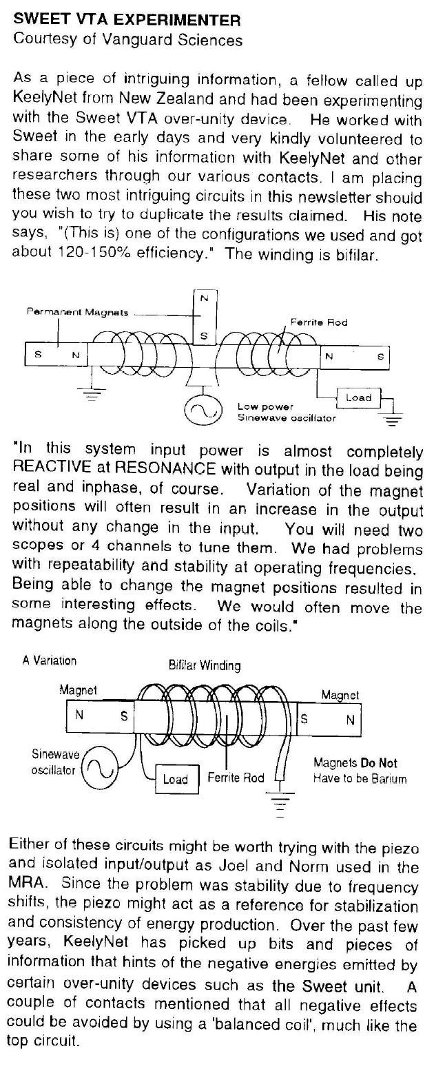
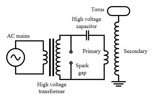
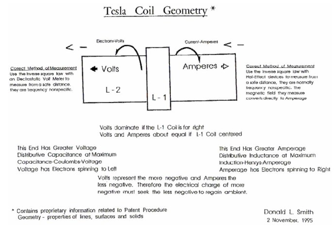
Floyd Sweet Wrote:
We are all familiar with AM and FM propagation, where in the case as AM, the voltage amplitude varies, and with FM, the frequency is modulated.
However, the output power sees a constant load impedance, that of the matched antenna system. If this changes, the input to the antenna is mismatched, and standing waves are generated resulting in a loss of power. The frequency is a forced response and remains constant. Power is lost and efficiency becomes less and less, depending on the degree of mismatch.
Ref: http://www.hyiq.org/Downloads/Magnetic%20Resonance%20by%20Floyd%20A.%20Sweet.%20PH.%20D.pdf
Now, we must think of Resonance and what it means!
Resonance:
In an electrical circuit, the condition that exists when the inductive reactance and the capacitive reactance are of equal magnitude, causing electrical energy to oscillate between the magnetic field of the inductor and the electric field of the capacitor.
Note 1: Resonance occurs because the collapsing magnetic field of the inductor generates an electric current in its windings that charges the capacitor and the discharging capacitor provides an electric current that builds the magnetic field in the inductor, and the process is repeated.
Note 2: At resonance, the series impedance of the two elements is at a minimum and the parallel impedance is a maximum. Resonance is used for tuning and filtering, because resonance occurs at a particular frequency for given values of inductance and capacitance. Resonance can be detrimental to the operation of communications circuits by causing unwanted sustained and transient oscillations that may cause noise, signal distortion, and damage to circuit elements.
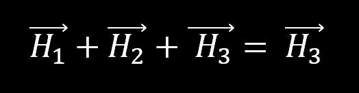
Note 3: At resonance the inductive reactance and the capacitive reactance are of equal magnitude. Therefore, ωL = 1/ ωC , where ω = 2πf , in which f is the resonant frequency in hertz, L is the inductance in henrys, and C is the capacity in farads when standard SI units are used. Thus,
f = π / 2 sqrt(LC)
Ref: https://www.its.bldrdoc.gov/fs-1037/dir-031/_4576.htm
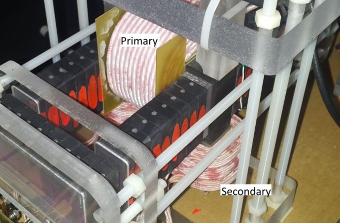
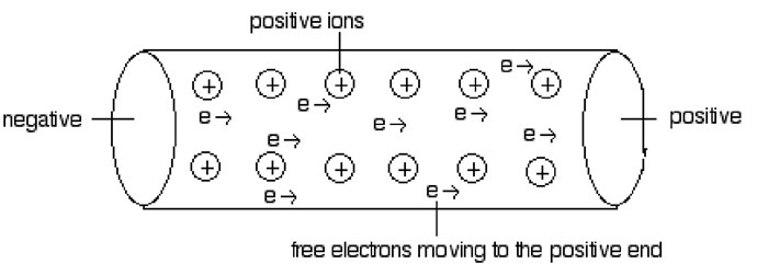
Consider the Length of Wire, this is very important!
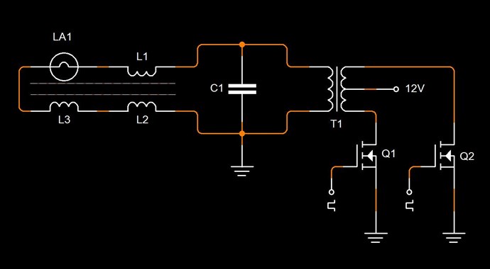
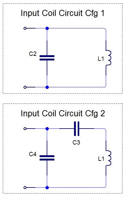
Capacitance between the Windings, Distributed Capacitance, and the Inductance, give rise to an LC Tank, where Resonance is achieved at a certain Frequency. This is where Inductive Reactance ( XL ) and Capacitive Reactance ( XC ) are Equal and thus cancel each other out. Both XL and XC have a value, but the Affects of each other Counter Balance, thus no XC or XL effects are seen.
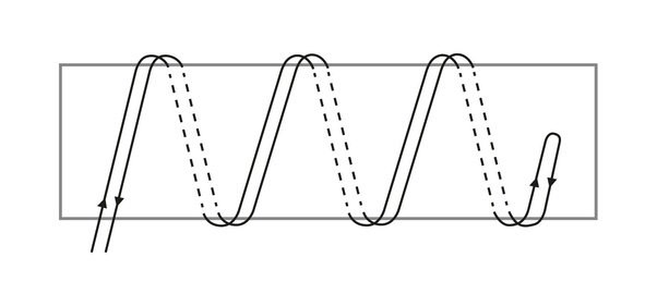
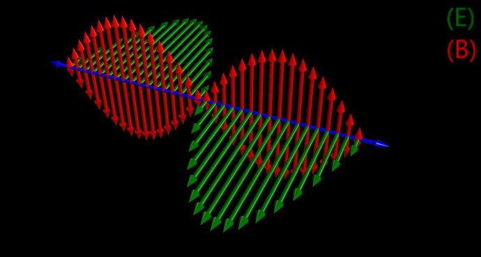
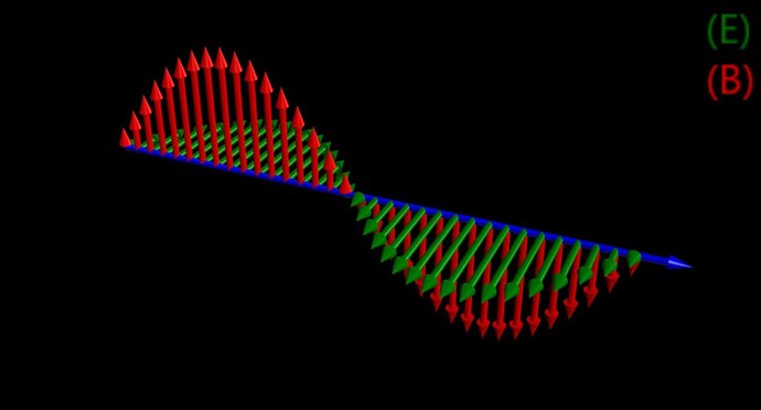
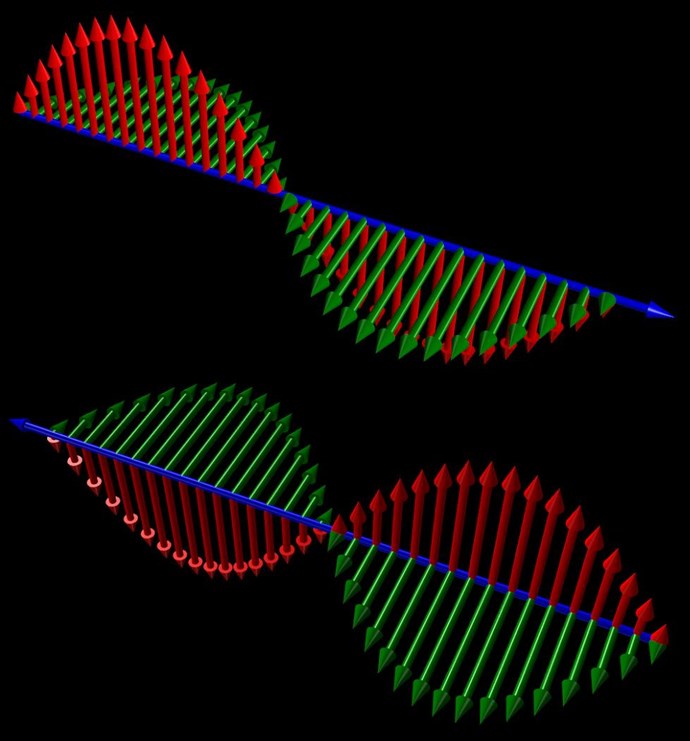
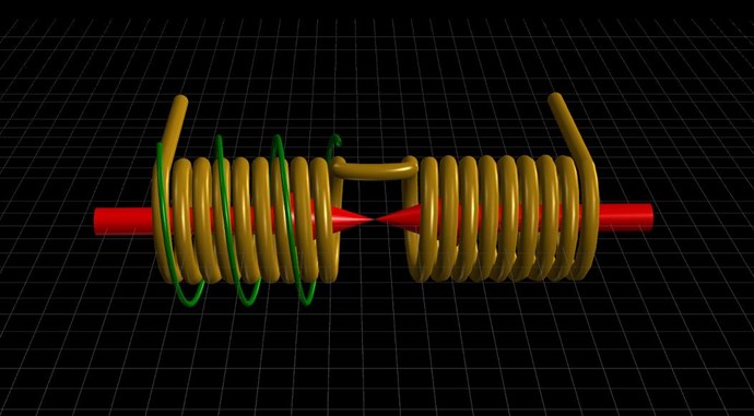
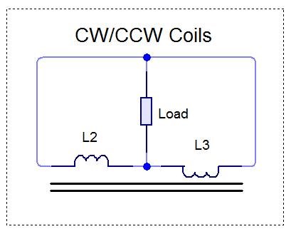
A Standing Wave, therefore is seen, at the exact Length of the Wire:
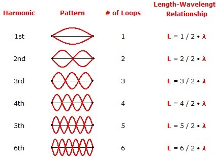
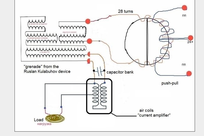
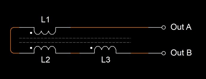
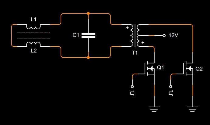
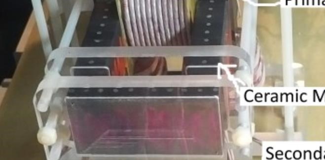
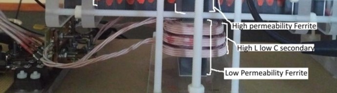
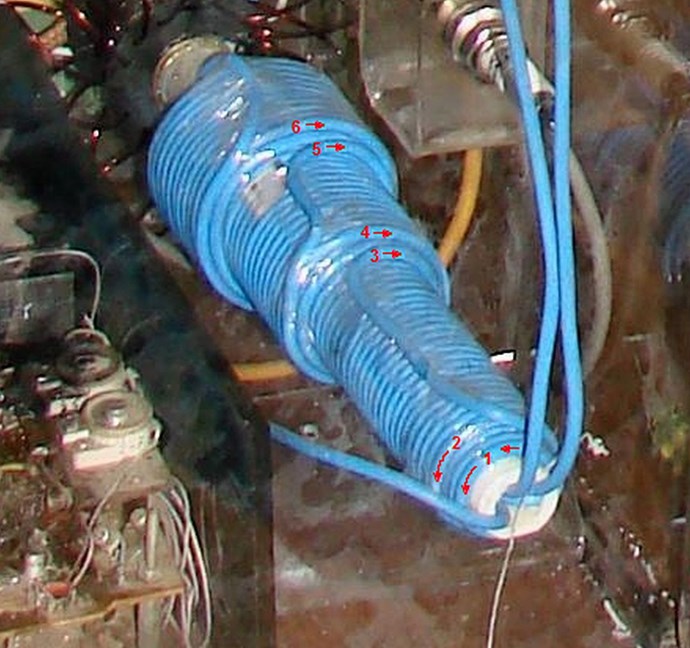
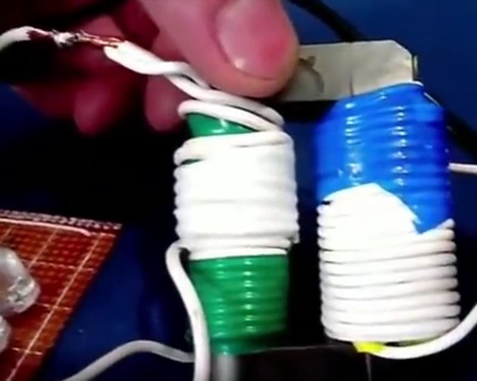
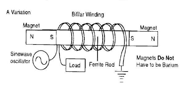
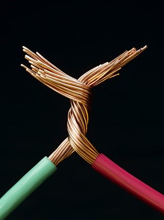
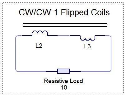
The 1st Harmonic has a Wavelength calculated by: L = 1/2 ⋅ λ, or a Harmonic there of, is the exact length of the Partnered Output Coils. The Insulated Copper Conductors, our Output Coils, are a Wave Guide:
So, we know for sure, as was stated in the above Quote from Floyd Sweet, at the time of this writing, he did not know how this technology worked.
We do not see: "...standing waves are generated resulting in a loss of power. The frequency is a forced response and remains constant. Power is lost and efficiency becomes less and less, depending on the degree of mismatch."
This does not happen.
We have NO reflection, no Impedance! The match of the Standing Wave, Wavelength, and the Output Coils are exactly the same!
Now, this post is perhaps the most important posted, so please, if you do not understand this post please ask!
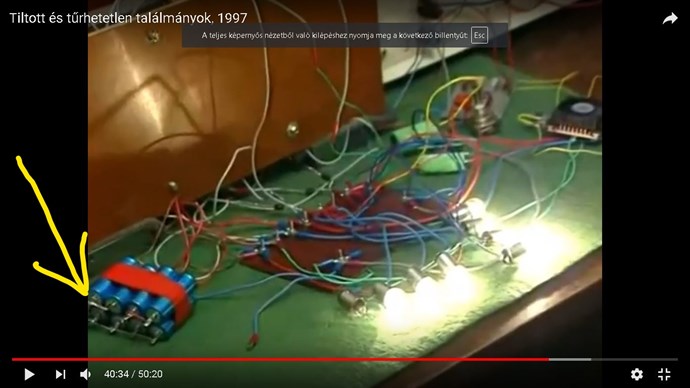
@Vidura, hope all is well now, Storm Damage can be extensive. Agreed! Many devices used this Tech! @Aloha and Jagau, thanks for info!
Chris