Design of an Advanced Power Management System

  • Topic Is Sticky
  • 839 Views
  • Last Post 21 November 2023
Chris posted this 22 January 2023

My Friends,

I have lived Off Grid for nearly Three Years now! 😉


Running your House directly from your newly built, Refined, Energy Machine, may not be the best idea, in case of fault or failure! Of course, a good, solid, Home Power System would have Redundancies!

To Power ones Home, one should implement an Advanced Power Management System! This is, in my opinion, a very important step, in becoming Power Independent!

Power used by any resource, the House, the Car or where you need power, will have Peak Power Requirements that any normal "Generator" will not always be able to handle! If your "Generator" is rated at 5KW and your instantaneous Peak Power Requirement is 8KW then you could damage, or destroy your "Generator"! Your Peak Power is 3KW over your Rated Output!

A Power Management System would have Fault or Failure protection built in, and will save you from damaging your Household items from Under-Voltage, Over-Voltage, Transients and so on!

Some Power Management Systems exist on the Market:


Solar Systems use Power Management Systems to Charge Batteries, or pump Power back into the Grid, from your Solar Panels. 


Please Note: I fully support Solar Systems as a part of the total solution! I do not support The Grid!

Solar Panels work by the very same base functionality as an Electric "Generator", using Charge Separation:


As we must realise by now, we must always have more Energy ( Voltage x Current x Cos ( θ ) x Time = Energy or Joules ) going into a system, than the System can Output, we always have Losses and they must be accounted for. 

By now, we can see, Power Management System Design is a very important aspect! Something we need to think about carefully!

If one chooses to follow the standard Model, then one would need an Inverter! Inverters have come a long way in recent years:


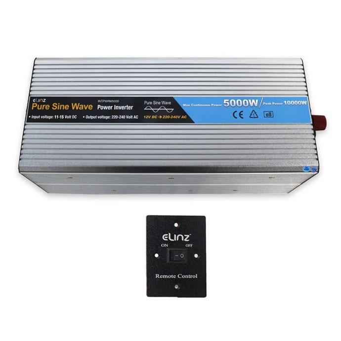
These days a 10KW Inverter has all sorts of fancy goodies built in, like Mobile Phone Wireless Monitoring: A SolaX 10kW Three Phase Hybrid Inverter at nearly $5K


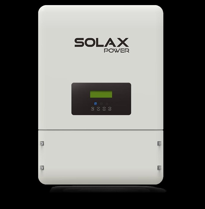
A nice Inverter, but somewhat pricey!

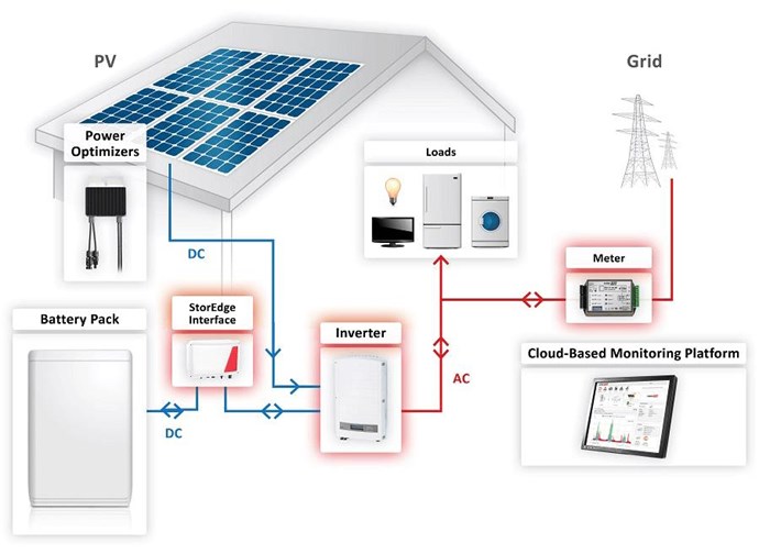
So a Home Power Management System might have a Layout something like this:


Where, the "Generator" would be your newly built, Refined, Energy Machine, that you have taken the time to learn how to build and make function, well Above the Unity Boundary!

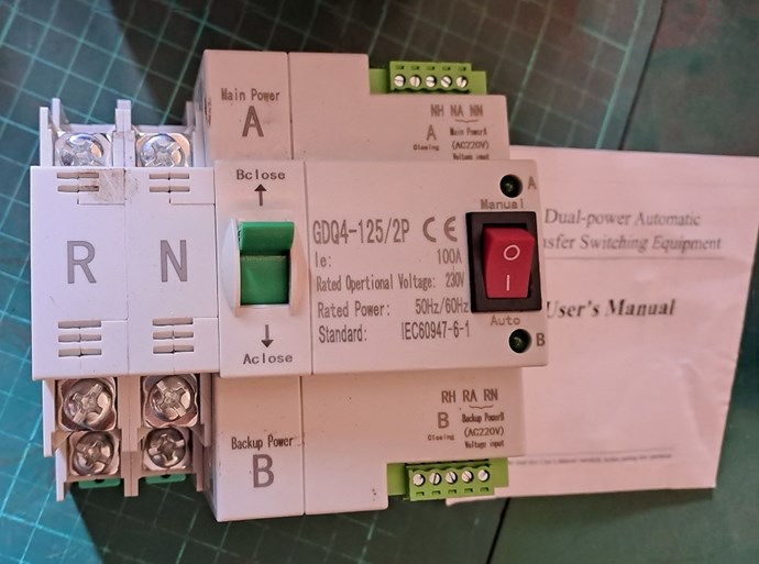
You can use an Automatic Transfer Switch to switch between Inputs as required, this is especially important at night, as your Batteries are getting Low on Charge:


Applying Solutions that give you the most reliability, at the best price and easiest implementation, is an important aspect also! If its not needed, and does not serve a Function, then leave it out! Apply the KISS Method! Keep It Simple Stupid!


An Installation video is worth overviewing:


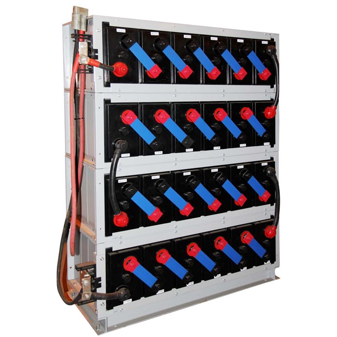
Batteries are pretty easy to install, but they are still some what pricey! A Battery Storage bank, to help you stay up and running over night is a good solution, just in case of Energy Machine Fault or Failure! One must ask the question, is a Battery Backup Bank worth the money? To answer this question, one must ask some fundamental questions:

  • Can you afford to loose the contents of your: Fridges, Freezers, or other Food storage appliances?
  • Can you and your Family be without Power for a Period, until Repairs can be completed?
  • What effects will be seen that are Negative from loosing Power for extended time?


You get the idea here?

How bigger a battery bank do you need? To answer this question, one needs to understand how batteries work to some degree:


So, for a 48 Volt System, to get you through the night, say 12 hours, and your average Power use is 2KW, you need: 48 Volts x 41.7 Amps x 12 hours, if my math is correct, which gives you a C Rating of?

CRating = I / E

  • Where CRating is the C rate
  • I is the current of charge/discharge (Amps)
  • E is the rated energy of the battery (Ah) (amp hours)


What is a C-rate? The C-rate is the unit battery experts use to measure the speed at which a battery is fully charged or discharged. For example, charging at a C-rate of 1C means that the battery is charged from 0-100% in one hour.

A 1C charge rate means that the current will charge the entire battery in 1 hour ( assuming you are starting with a fully discharged battery around 3.2v ). For example, if you had a 1000mAh lipo, to charge at 1C you would set your charger for 1 Amp. If you had a 500mAh battery, you would set your charger to 0.5 Amps.

C-rate is defined as the charge / discharge current divided by the nominally rated battery capacity. For example, a 5,000 mA charge on a 2,500 mAh rated battery would be a 2C rate.


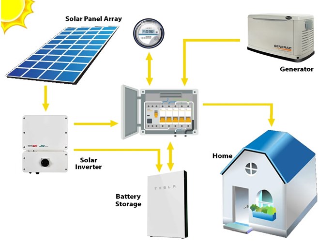
My opinion, its worth looking at seriously to have that backup there! Tesla does a Battery Wall to avoid Loosing Power, and loosing Power Sucks! Power Storage is sensible!

Energy Machines are only as good as the total refinement, and quality, that they are constructed with. Yes, I have an Automatic Transfer Switch for Power Protection and Redundancy!

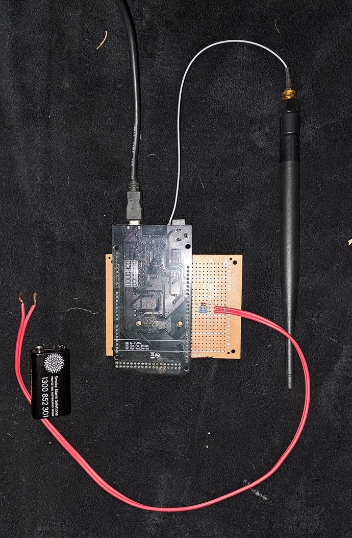
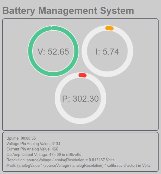
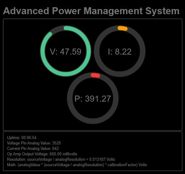
It is possible to build your own System, and use some purchased items, maybe an Inverter and some heavy duty Switches. A System Controlled by a Microcontroller is more than possible! Power Monitoring and Charging of Batteries is a common thing in many Systems!

This has been done already:

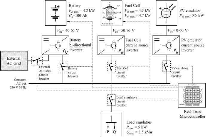
Ref: Microcontroller-Based Power Management System

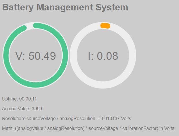
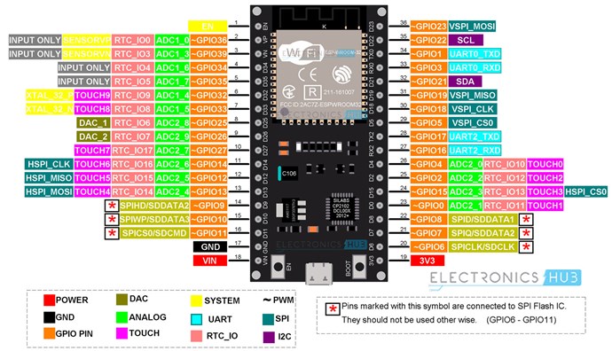
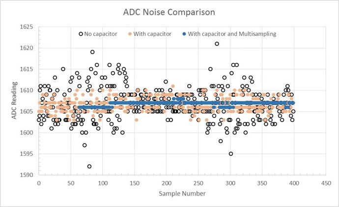
Of course, we have been through Measurements many times, but using a Microcontroller is a little different and requires a little bit of planning!

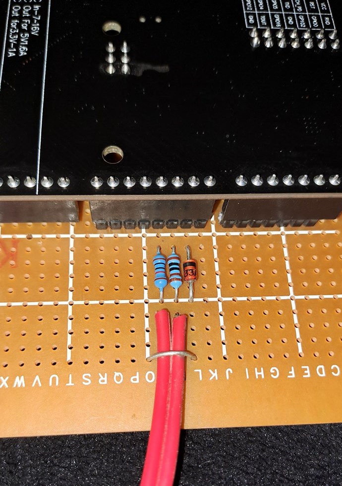
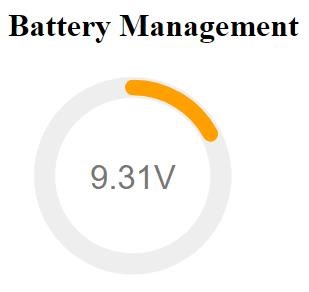
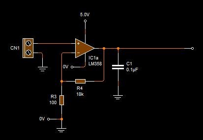
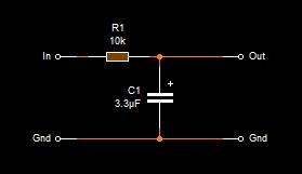
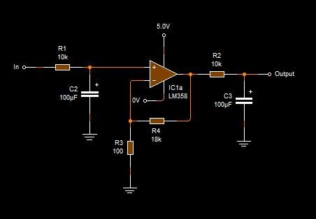
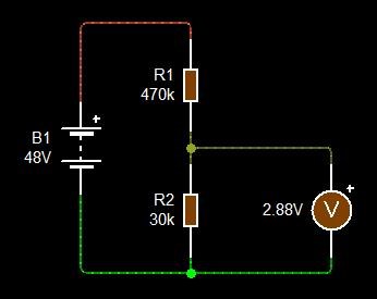
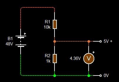
Voltage into the Microcontroller must be at or lower than the rated Pin Voltage, normally 5Volts but sometimes 3.3Volts, so check your Data sheet! To measure this Voltage, we use a Voltage Divider:

Here is a good Video on doing this:


This is also good:


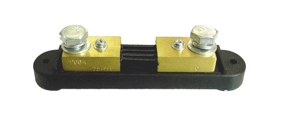
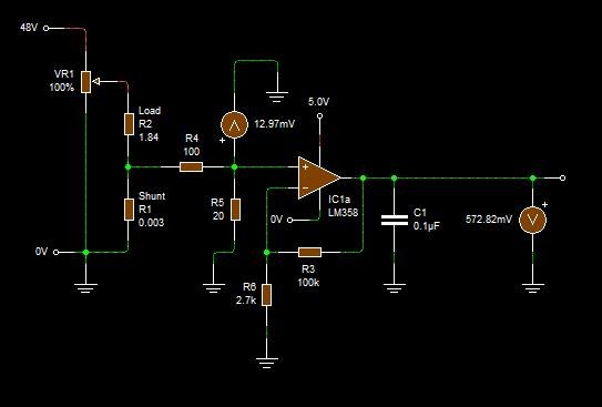
Measuring Current, also very easy:


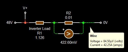
You can see, the Current is calculated using Ohms Law: Current I = Voltage V / Resistance R = 0.4226 Volts / 0.01 Ohms = 42.26 Amps which is what we get in the Sim.

Note: The Reciprocal of the Current Shunt Resistance R, can be multiplied to get the Amperage in Amps, for example: ( 1 / 0.01 ( The Reciprocal )) = 100, so if we use the Voltage V: 0.4226 Volts x the Reciprocal: 100, we get: 0.4226 Volts x 100 = 42.26 Amps. The same answer! The Watts = 2,028.48 Watts, also the same.

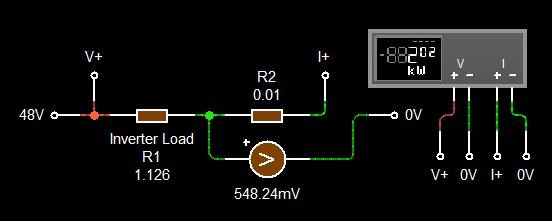
Checking with the build in Wattmeter, we get the same answer.

Something to think about is the Power the Current Shunt Resistor will dissipate:


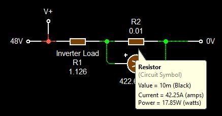
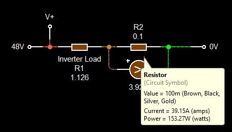
Interesting to note the big difference, remembering that Power is: Power P = Current I2 x Resistance R. Current I2 = 1785.908 Amps x Resistance R 0.01 = 17.85908 Watts, or Current I2 = 1532.7225 Amps x Resistance R 0.1 = 153.27225 Watts. So Power burning up inside Current Shunts is not the most efficient way of doing things! A difference of: 153.27225 Watts - 17.85908 Watts = 135.41317Watts saved by using a different Current Shunt Resistor.


Note: No images used in this thread are of My System. For the mean time, I choose to keep my System to My Self for Security Reasons.

Best Wishes,

   Chris

Order By: Standard | Newest | Votes
donovan posted this 22 January 2023

Hi,

So much information!

I live off grid.....and as soon as I get a machine working....it will be connected to my systems.....

My plan, is to have the machine put out a voltage and current similar to one of my solar panel arrays.  I would design the machine output to replicate a solar panel.....a constant current device, for the most part.  And have it connected in parallel with the existing solar arrays.  And then let the solar charger function like normally.  And yes, the machine would have to have protection devices built in to make sure there was no over current or over voltage events.

Donovan

Chris posted this 23 January 2023

My Friends,

On this Thread I am going to build and share an Advanced Home Power Management System. 

Here is an Image of My Automatic Transfer Switch:


As you can see, if the Generator stops Working, the Inverter kicks in and the House does not loose power.

As you can see, its quite old. The Output light is faulty and flashes intermittently Some of My Equipment is on the older side, so I am at a point where I need to do something about My System.

I am thinking about a Microcontroller based System that I described above.

Best Wishes,

   Chris

Chris posted this 23 January 2023

My Friends,

Talking about Fault or Failure, the last 10 hours or so I have had some issues, not resolved, It appears, but a faulty Fuse was causing all sorts of issues, on both systems:


What a Pain! Hard to fix in the middle of the night, dark and all you have is a small torch to use, when one does not have a spare Blade Fuse!

I guess, this is a big thing in the Design Topic of this thread!

Best Wishes,

   Chris

Chris posted this 28 September 2023

My Friends,

Today I want to share a simple Prototype Circuit and some Code:

///////////////////////////////////////////////////////////////////////////////////////////////////////////////////////////////////////
// Header:                                                                                                                           //
////////////////////////////////////////                                                                                             //
// Includes:                          //                                                                                             //
#include "WiFiEsp.h"                  // ESP8266 WiFi Library...                                                                     //
///////////////////////////////////////////////////////////////////////////////////////////////////////////////////////////////////////


///////////////////////////////////////////////////////////////////////////////////////////////////////////////////////////////////////
// WiFi Esp Client:                                                                                                                  //
////////////////////////////////////////                                                                                             //
// Initialize WiFi Client:            //                                                                                             //
WiFiEspClient client;                 // A Client that makes a Connection.                                                           //
                                      //                                                                                             //
WiFiEspServer server(80);             // Init the WiFi Web Server on Port 80.                                                        //
                                      //                                                                                             //
int status = WL_IDLE_STATUS;          // The Wifi radio's status                                                                     //
                                      //                                                                                             //
// WiFi Credentials:                  //                                                                                             //
char ssid[] = "YourSSID";               // Your Network SSID (name)                                                                    //
char pass[] = "YourPassword";             // Your Network Password                                                                       //
                                      //                                                                                             //
///////////////////////////////////////////////////////////////////////////////////////////////////////////////////////////////////////


///////////////////////////////////////////////////////////////////////////////////////////////////////////////////////////////////////
// Voltage Divider Sensor Init:                                                                                                      //
////////////////////////////////////////                                                                                             //
// Voltage Divider Sensor Init:       //                                                                                             //
const int analogPin = A3;             // Analog Voltage Divider Pin.                                                                 //
float analogVoltageValue;             // Analog value on voltageSensorPin (0 - 1023).                                                //
float vOut;                           // Voltage Divider Output Voltage.                                                             //
float vMax = 54.50;                   // Maximum Input Voltage.                                                                      //
const float factor = 11.77;           // Reduction factor of the Voltage Sensor shield.                                              //
const float analogVCC = 5.00;         // Arduino Analog Pin voltage Threshold 5V or 3.3V.                                            //
///////////////////////////////////////////////////////////////////////////////////////////////////////////////////////////////////////


///////////////////////////////////////////////////////////////////////////////////////////////////////////////////////////////////////
// The Server Response Header:                                                                                                       //
//////////////////////////////////////////////////                                                                                   //
const String Header = "HTTP/1.1 200 OK\r\n"     //                                                                                   //
                "Content-Type: text/html\r\n"   //                                                                                   //
                "Connection: close\r\n"         // the connection will be closed after completion of the response                    //
                "Refresh: 30\r\n"               // refresh the page automatically every 30 sec                                       //
                "\r\n";                         //                                                                                   //
///////////////////////////////////////////////////////////////////////////////////////////////////////////////////////////////////////


///////////////////////////////////////////////////////////////////////////////////////////////////////////////////////////////////////
// Home Page Template Init:                                                                                                          //
///////////////////////////////////////////////////////////////////////////////////////                                              //
const String HomePageTemplate =                                                      //                                              //
          "<!DOCTYPE html>\r\n"
          "<html lang='en'>\r\n"
          "<head>\r\n"
          "<meta charset='UTF-8'>\r\n"
          "<meta http-equiv='X-UA-Compatible' content='IE=edge'>\r\n"
          "<meta name='viewport' content='width=device-width, initial-scale=1.0'>\r\n"
          "<title>Battery Management System</title>\r\n"
          "<!-- CODE: https://medium.com/@pppped/how-to-code-a-responsive-circular-percentage-chart-with-svg-and-css-3632f8cd7705 -->\r\n"
          "<style> \r\n"
          ".flex-wrapper { "
          "display: flex; "
          "flex-flow: row nowrap; "
          "} \r\n"

          ".single-chart { "
          "width: 33%; "
          "justify-content: space-around; "
          "} \r\n"

          ".circular-chart { "
          "display: block; "
          "margin: 10px auto; "
          "max-width: 80%; "
          "max-height: 250px; "
          "} \r\n"

          ".circle-bg { "
          "fill: none; "
          "stroke: #eee; "
          "stroke-width: 3.8; "
          "} \r\n"

          ".circle { "
          "fill: none; "
          "stroke-width: 2.8; "
          "stroke-linecap: round; "
          "animation: progress 1s ease-out forwards; "
          "} \r\n"

          "@keyframes progress { "
          "0% { "
          "stroke-dasharray: 0 100; "
          "} "
          "} \r\n"

          ".circular-chart.orange .circle { "
          "stroke: #ff9f00; "
          "} \r\n"

          ".circular-chart.blue .circle { "
          "stroke: #3c9ee5; "
          "} \r\n"

          ".circular-chart.green .circle { "
          "stroke: #4CC790; "
          "} \r\n"

          ".percentage { "
          "fill: #777; "
          "font-family: sans-serif; "
          "font-size: 0.37em; "
          "text-anchor: middle; "
          "} \r\n"
          "</style>\r\n"
          "</head>\r\n"                                                              //                                              //
                                                                                     //                                              //
          "<body>\r\n"                                                               //                                              //
          "<h1>Battery Management</h1>\r\n"                                          //                                              //
          "<div class='flex-wrapper'>\r\n"                                           //                                              //
          "<div class='single-chart'> \r\n"                                          //                                              //
          "<svg viewBox='0 0 36 36' class='%Colour%'> \r\n"                          //                                              //
          "<path class='circle-bg' \r\n"                                             //                                              //
          "d='M18 2.0845 a 15.9155 15.9155 0 0 1 0 31.831 a 15.9155 15.9155 0 0 1 0 -31.831'/> \r\n" //                              //
          "<path class='circle' \r\n"                                                //                                              //
          "stroke-dasharray='%Percent%, 100' \r\n"                                   //                                              //
          "d='M18 2.0845 a 15.9155 15.9155 0 0 1 0 31.831 a 15.9155 15.9155 0 0 1 0 -31.831'/> \r\n" //                              //
          "<text x='18' y='20.35' class='percentage'>%Volts%V</text> \r\n"           //                                              //
          "</svg> \r\n"                                                              //                                              //
          "</div> \r\n"                                                              //                                              //
          "</div> \r\n"                                                              //                                              //
          "</body>\r\n"                                                              //                                              //
          "</html>\r\n";                                                             //                                              //
///////////////////////////////////////////////////////////////////////////////////////////////////////////////////////////////////////


///////////////////////////////////////////////////////////////////////////////////////////////////////////////////////////////////////
// Setup the Board:                                                                                                                  //
///////////////////////////////////////////////////////////////////////////////////////////////////////////////////////////////////////
void setup() {

  // Initialize Debugging Serial:
  Serial.begin(115200);

  // Initialize serial for ESP module: COM3 = Srial3
  Serial3.begin(115200);

  // Initialize ESP8266 Module:
  WiFi.init(&Serial3);

  // Check ESP8266 Status:
  if (WiFi.status() == WL_NO_SHIELD) {

    Serial.println("[Mega 2560] WiFi shield not present");

    // don't continue
    while (true);
  }

  // Attempt to connect to WiFi network:
  while (status != WL_CONNECTED) {

    Serial.print("[Mega 2560] Attempting to connect to WPA SSID: ");
    Serial.println(ssid);

    // Connect to WPA/WPA2 Network:
    status = WiFi.begin(ssid, pass);
  }

  // Start the Web Server on Port: 80
  server.begin();

  // You're connected:
  Serial.println("[Mega 2560] You're connected to the network");

  // Print the SSID of the Network:
  Serial.print("[Mega 2560] SSID: ");
  Serial.println(WiFi.SSID());

  // Print your ESP8266 WiFi IP Address:
  IPAddress ip = WiFi.localIP();
  Serial.print("[Mega 2560] IP Address: ");
  Serial.println(ip);

  // Print Signal Strength:
  long rssi = WiFi.RSSI();
  Serial.print("[Mega 2560] Signal strength (RSSI):");
  Serial.print(rssi);
  Serial.println(" dBm");
}


///////////////////////////////////////////////////////////////////////////////////////////////////////////////////////////////////////
// Board Main Loop:                                                                                                                  //
///////////////////////////////////////////////////////////////////////////////////////////////////////////////////////////////////////
void loop() {

  // Listen for incoming Clients:
  client = server.available();

  // If we have a Client:
  if (client) {

    // A http request ends with a blank line:
    boolean currentLineIsBlank = true;

    // While Connected:
    while (client.connected()) {

      // If Client Avaliable:
      if (client.available()) {

        // Read Client Request:
        char ClientRequest = client.read();

        // Write to the Serial Port:
        Serial3.write(ClientRequest);

        // Delay to let ESP8266 Read and process the Data:
        delay(70);

        // If you've gotten to the end of the line (received a newline
        // character) and the line is blank, the http request has ended,
        // so you can send a reply
        if (ClientRequest == '\n' && currentLineIsBlank) {

          analogVoltageValue = analogRead(analogPin);         // read the current sensor value (0 - 1023)
          vOut = (analogVCC / 1024) * analogVoltageValue * factor;     // convert the value to the real voltage on the analog pin

          // Get the Percentage:
          float Percent = vOut / vMax * 100.0;

          // Prepare the Html Document, Home Page:
          String HomePage = HomePageTemplate;
          HomePage.replace("%Volts%", String(vOut));
          HomePage.replace("%Percent%", String(Percent));

          // Set the Colour:
          if(vOut <= 46.7)
            HomePage.replace("%Colour%", "circular-chart orange");
          else if(vOut <= 47.7)
            HomePage.replace("%Colour%", "circular-chart blue");
          else if(vOut > 47.7)
            HomePage.replace("%Colour%", "circular-chart green");


          // Mega 2560 Send Response:
          Serial.println("[Mega 2560] Sending Response");

          // Send a standard Http Response Header:
          client.print(Header);

          // Send the Html Document, Home Page:
          client.print(HomePage);

           // We are done:
          break;
        }
        if (ClientRequest == '\n') {

          // You're starting a new line:
          currentLineIsBlank = true;
        } 
        else if (ClientRequest != '\r') {

          // You've gotten a character on the current line:
          currentLineIsBlank = false;
        }
      }
    }

    // Give the Web Browser time to Receive and Process the Data:
    delay(100);

    // Close the connection:
    client.stop();
  }
}


The Circuit:


The Circuit and the MCU:


The Webpage:


I hope this is of some help to others, and yes as a test, I am measuring a 9Volt Battery as the source. 

Best Wishes,

   Chris

Chris posted this 06 October 2023

My Friends,

A simple Power Meter, to monitor Power In and Out of Battery Banks and so on, is slowly progressing, via an internally configured Webpage I have setup: 


Of course, accuracy is not perfect, but this is calibrated to approximately 2%, and for a system like this, its plenty accurate enough!

I have written the code, and its still a work in progress, so I will share the code another post.

I have a 200 Amp 75mV Current Shunt in place.

Voltage: 75mV dc
Current Capacity: 250A
For use with M10 cable lug.
Standby Current 7mA
Dimensions: Approx ~ 75 x 25 x 30mm
Weight: 0.6kg
Model: SH200


I needed to implement a Current Sensing Amplifier, to amplify the millivolt reading so the Microcontroller ( Now using an ESP32 WROOM with a LM358N ) can read it with accuracy, as 1 or 2 millivolts are very hard to get an accurate reading on, one will need to amplify the voltage to a minimum of around 20 millivolts to get an accurate reading.


Non-Inverting Amplifier


Here is a quick vid to explain a little more:


Differential Amplifier

My Circuit, which I am prototyping atm, because the Circuits above gave me some problems, to measure the Shunt Current is a little different:


  • Gain AV = 1 + 100,000.00 / 2700.00 = 38.037
  • Input Voltage Divider Range: 0 - 75mV
  • Input Voltage Divider Ratio: 1 : 0.16 where 75mV * 0.16 = 12mV


Sometimes I worry about the Community, because some Circuits out there just don't work, and there is no explanation why. Here, you need to divide the Input Voltage, because the LM358N will Saturate at very low input voltages. Best way, check your datasheet or measure the Input Voltage Tolerance, and design a Voltage Divider on the Input to compensate.

This gives me a very nice linear response through the Range I have worked on. Zero to 200 Amps.

NOTE: The Resistor at R6 would be better to be a 2.4K and not a 2.7K, then the Output Voltage would be lower, and not run the risk of damaging the Microcontroller if you get High Currents. At 200Amps with a 75mV input, the Op Amp see's an input of 12mV, below Saturation Voltage, and the Output Voltage is 3.7 Volts, the Microcontroller should not have more than 3.3 Volts Input! So there is a problem here.

At low Current, the Resolution is poor, so we do have a Resolution issue atm.

This is still a work in motion and is not yet perfected by any means! This is a pretty accurate configuration at the moment, but more work is required to further improve this circuit.

This is a very cheap, and a very simple, WiFi Wattmeter that's accessible via a Webpage, how cool is that, I think that's very cool!

Best Wishes,

   Chris

Chris posted this 10 October 2023

My Friends,

After some messing around, I was not happy with the Current Sensing Circuit, so I went back to the Non-Inverting Amplifier Circuit and rechecked some parameters.

Currently, I am getting better results, with a lot more resolution:


I have pushed the Gain way up compared to what it was. I was using around 34 from memory.

I am using: Gain = 1.0 + 18000.0 / 100.0 = 181, which is currently looking ok.

I think this is a better approach, using a Non-Inverting Amplifier compared to a Differential Amplifier to Amplify Sensing Current.

Best Wishes,

   Chris

Chris posted this 12 October 2023

My Friends,

Trivial, but I thought I would bring this up, I have implemented a Low Pass Filter on the Input to the Op Amp, to filter out Noise:

I believe I will end up with a filter on the Output also. I think a 10K resistor and a 100uF cap. That should stop the noise and give me a flat DC reading for the Analog Pins!


Doing some more testing, this is a Calibration Test again:


This is all running from a tiny ESP32:


Those out there more experienced than me, please feel free to chime in and make suggestions! What I am implementing may not be the best way to do this, and there is always a better way, so please point out any thing you think would help!

Currently, the setup I have, the prototype, is working very good! I would really like to make it better however!

Perhaps this is a bit too advanced for the other forums, that's why you see none of this sort of thing on the other forums! Realistically, this is very simple, and its just a case of making steps on improvement, making this more and more useful at every step!

Best Wishes,

   Chris

Plasmonic posted this 12 October 2023

Hello Chris,

If the controller isn't too busy with other analog reads or CPU load you may be able to connect the output of the OpAmp to a pin on each ADC channel.  It ought to give you a trade off of being able to average the two results and thus be able to reduce your filter values.

Edit You may not need to use both channels but just average the results within the desired time from the one pin.

Probably the biggest advantage is that if the filter is the slowest part, you should be able to get a significant gain in response time.

Be Well,

Matt


Chris posted this 12 October 2023

Thanks Matt!

Good advice there!

I have implemented several things, because I have not yet shared my updated code, they are not yet visible but I have Software Multisampling implemented and Hardware Filtering also occurring. My response time is pretty good to be honest!

Software multisampling:

  // Total of n Samples:
  int total = 0;

  // Loop for n samples:
  for(int i = 0; i < samples; i++)
  {
    // Take a sample:
    total += analogRead(analogPin);
  }


and Hardware Filtering:


Using these two techniques, I have eliminated nearly all noise and am getting very good very stable results! I can see DC on the Output Pin, with no Noise what so ever, just a Varying DC as the Input Changes.

A good chart here:

Ref: Measure analog voltage on ESP32 with ADC - upesy.com


You can see how accurate it can be when both are used.

CPU Time seems to be good atm, so I am confident that we are all good there.

Best Wishes,

   Chris

Chris posted this 13 October 2023

My Friends,

An ATS, Automatic Transfer Switch, is one of the most useful devices one can employ to keep a System up and running! In the event of one Power Source failing, Break Down or some sort of failure, we can employ an Automatic Transfer Switch to automatically switch over to the second source, and keep your System Operational.

I have purchased a new Automatic Transfer Switch:


A bit of an upgrade, from a 40 Amp Automatic Transfer Switch, image above and also below, to a 100 Amp Automatic Transfer Switch! Quite reasonably priced also!


If you are not familiar with Automatic Transfer Switches, here are two very good videos, explain how they work and how to wire them:


Power Distribution Boxes have many available devices, and some terms heard in the above video may not be clear, so here is a small list of the devices and the terminology:

  • MCB: Miniature Circuit Breaker
  • RCCB: Residual Current Circuit Breaker
  • RCBO: Residual Current Circuit Breaker with Overcurrent Protection


More coming soon on this topic, as much more must be covered.

Best Wishes,

   Chris

Chris posted this 18 November 2023

My Friends,

In my prototyping stages, silly me, I ignored some simple rules due to my insistence of learning the hard way, my Voltage Divider was giving me some pretty average accuracy sometimes.

I was using a 10K and a 1K Resistor:


Because its what I had on hand, but I was not happy with the result, I wanted to make this much more stable and accurate, so I went with good advice that is industry standard, use much higher values, reducing the current draw, and accuracy has improved drastically:


The use of a Voltage Divider Calculator makes the task of selecting Resistors for a given output Voltage much easier, selecting 470K and a 30K, odd resistor, so I temporarily implemented three 10K Resistors in series, gives me a Current of: 96μA, which is not bad.

Accuracy has improved a lot, and my, all be it slow prototyping, is getting there.

My Backup System, implementing an Energy Machine and Solar Panels and Batteries, gives me a reasonable System, that is fairly stable most of the time. The Automatic Transfer Switch is a very useful Tool!


I do still have issues! Some things occur that cant be explained!

Best Wishes,

   Chris

Chris posted this 19 November 2023

My Friends,

The Power is in YOUR Hands, knowledge and the application of Knowledge is Power, and because we are light years ahead, we are able to design and build systems that are simple yet very powerful!

Every Energy Machine must be started, and usually its via a Battery or something similar. A Smart way to design any System is to have as much Backup System as possible, without having too much associated cost. Solar I support like I have always said, so incorporating this into your system is smart. If you have a Breakdown, which does occur, you need Power to fix your Machine most of the time, soldering new components and so on!

Here is a Battery Test, from my prototyped Advanced Power Management System:


I am in very early stages, still, so no I wont be sharing the code yet, maybe later on, when I get the whole system fully operational. I realised I had an inconsistency, the Naming Convention was wrong, it should not be "Battery Management System", because its not, it is an "Advanced Power Management System", and so, I have updated my Code to reflect this correction.

Of course, we don't want Plagiarists to copy it and claim it as their own! We see a lot of this don't we!

This System will have more advanced feature's coming soon, I have some implemented already, like:

  • Alexa, switch to Backup Power
  • Alexa, what time of day is maximum power usage
  • and so on...


Using IOT:


Power monitoring is a small part of the System!

Best Wishes,

   Chris

thaelin posted this 21 November 2023

   Been looking into what is called LORA and can run on arduino's and ESP32's. Quite the system and seems to have a easy programming curve. Is that what you are using to get the reported stats? Just curious. Display looks good with the circular dials. 

thay


  • Liked by
  • Chris
Chris posted this 21 November 2023

Hi Thay,

Yes a little C++, very easy to get something working, especially if you can combine it with other things like HTML, Javascript/JQuery and so on.

For those that dont know what LORA is:


BEWARE: its been confirmed to be dangerous:


Keep your boys running free and dont expose them to the bad radiation!

Best Wishes,

   Chris

We're Light Years Ahead!
Members Online:
What is a Scalar:

In physics, scalars are physical quantities that are unaffected by changes to a vector space basis. Scalars are often accompanied by units of measurement, as in "10 cm". Examples of scalar quantities are mass, distance, charge, volume, time, speed, and the magnitude of physical vectors in general.

You need to forget the Non-Sense that some spout with out knowing the actual Definition of the word Scalar! Some people talk absolute Bull Sh*t!

The pressure P in the formula P = pgh, pgh is a scalar that tells you the amount of this squashing force per unit area in a fluid.

A Scalar, having both direction and magnitude, can be anything! The Magnetic Field, a Charge moving, yet some Numb Nuts think it means Magic Science!

Message from God:

Hello my children. This is Yahweh, the one true Lord. You have found creation's secret. Now share it peacefully with the world.

Ref: Message from God written inside the Human Genome

God be in my head, and in my thinking.

God be in my eyes, and in my looking.

God be in my mouth, and in my speaking.

Oh, God be in my heart, and in my understanding.

Your Support:

More than anything else, your contributions to this forum are most important! We are trying to actively get all visitors involved, but we do only have a few main contributors, which are very much appreciated! If you would like to see more pages with more detailed experiments and answers, perhaps a contribution of another type maybe possible:

PayPal De-Platformed me!

They REFUSE to tell me why!

We now use Wise!

Donate
Use E-Mail: Chris at aboveunity.com

The content I am sharing is not only unique, but is changing the world as we know it! Please Support Us!

Thank You So Much!

Weeks High Earners:
The great Nikola Tesla:

Ere many generations pass, our machinery will be driven by a power obtainable at any point of the universe. This idea is not novel. Men have been led to it long ago by instinct or reason. It has been expressed in many ways, and in many places, in the history of old and new. We find it in the delightful myth of Antheus, who drives power from the earth; we find it among the subtle speculations of one of your splendid mathematicians, and in many hints and statements of thinkers of the present time. Throughout space there is energy. Is this energy static or kinetic? If static, our hopes are in vain; if kinetic - and this we know it is for certain - then it is a mere question of time when men will succeed in attaching their machinery to the very wheelwork of nature.

Experiments With Alternate Currents Of High Potential And High Frequency (February 1892).

Close