

My Friends,
Today, I want to cover something that is not only simple, but extremely important to understand!
All Electrical Components have the fundamental properties of:
- Resistance
- Inductance
- Capacitance
Some Components have other Properties, but I would not call these Fundamental:
- Impedance
- Reactance, both Capacitive and inductive
- and more...
Today I want to specifically talk about the Dipole Antenna and its Parasitic Capacitance, in other words, a Value of Capacitance that the Dipole Antennas has, no matter what measures are taken to try to circumvent this!
I first want to refer to the following document: Electromagnetic Compatibility Engineering, by Henry W. Ott
In this document, you will find an image like so:
I wish to quote the text pertaining to this image:
D.1 BASIC DIPOLES FOR DUMMIES
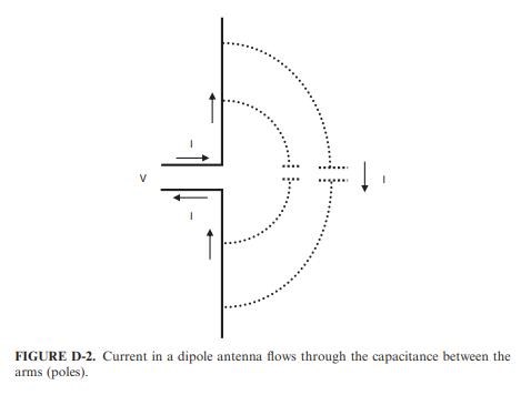
A dipole is a basic antenna structure that consists of two straight collinear wires (arms or poles) as depicted in Fig. D-1. The first thing to notice about a dipole is that it has two parts, hence, the term ‘‘di’’ in its name. How can we explain the fact that it is possible to drive current into a dipole when the ends are open, and we, therefore, do not have a closed loop? The simplest way to resolve this seeming dilemma, without getting involved with electromagnetic field theory, is to consider the parasitic capacitance between the two arms (poles) of the antenna as the return current path, as shown in Fig. D-2. At high frequency, this capacitance will represent a low impedance. Current through this uncontrolled parasitic capacitance represents radiation. Therefore, a dipole requires two parts to radiate and the amount of radiation will be proportional to the dipole current. Note also from Fig. D-2
Ref: Dipoles for Electromagnetic Compatibility Engineering, by Henry W. Ott - Dummies
Now, I want to state, if the Intrinsic Capacitance were to change its Value in any direction, up or down, this would change the Fundamental Properties of the Dipole Antenna and as a result, it would exhibit different reactionary characteristics, it would Resonate at a different Frequency!
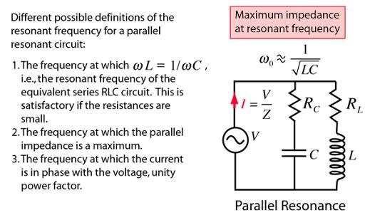
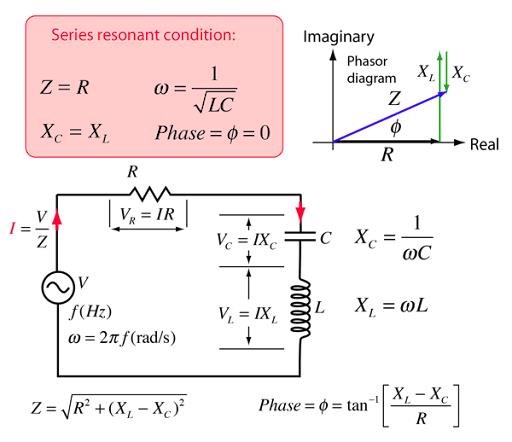
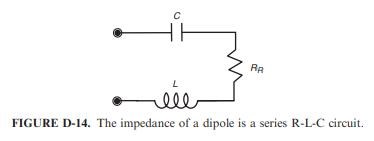
Most Electrical Engineers will tell you any RLC Circuit is Resonant because of the Resistance, Capacitance and the Inductance:
And, that a Dipole Antenna is not the same! Electrical Engineers will likely argue that the Antenna can not be resembled to an RLC Resonant Circuit! Mostly anyway!
The truth is, this is totally false and fabricated!
An Antenna's Resonant Properties are, in fact, exactly the same as the RLC Circuit shown above, only, as the Capacitance, or, as a matter of fact, any Fundamental Property changes, the Resonant Frequency will also change!
Again, let me quote:
D.3.2 Dipole Resonance
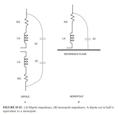
Refering to Fig D-14 we can conclude that below the resonant frequency the input impedance to the antenna will be large (W 1000 O) because of the
impedance of the capacitor. Above the resonant frequency, the impedance will also be large (W 1000 O) because of the impedance of the inductor. At resonance, however, the impedance will be low (around 70 O for a dipole and 35 O for a monopole) because, at resonance, the inductive reactance will cancel the capacitive reactance, which leaves just the radiation resistance. It will be difficult for the common-mode voltage (or any other voltage for that matter) to drive much current into the antenna when the input impedance is large. However, it will be easy to drive current into an antenna at resonance, when the impedance is low. Therefore, dipole (monopole) resonance is important with respect to EMC. At the resonant frequency, it is much easier to couple energy into or extract energy from the antenna, and it will therefore be a more efficient radiator or receptor of electromagnetic energy.
In the literature, we have an Analogy between RLC Resonant Circuit, and an Antenna! An important aspect to take on board!
Now we have said for a long time, the Coil or Inductor is simply just an Antenna!
This is true! Because we have a Change in Parasitic Capacitance when we Change the Geometry of the Antenna, thus:
winding it tightly on a Former, changes the Parasitic Capacitance,
thus the Resonant Frequency also Changes! Very Simple and Very Easy to Understand!
As it turns out, the resonant frequency of a dipole (or monopole) is related to its length. Resonance will occur when the length of one of the antenna arms (elements) is one quarter wavelength. Therefore, a dipole will be resonant when its overall length is equal to one half a wavelength, and a monopole will be resonant when its length is one quarter wavelength.
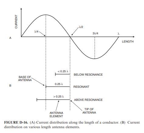
Why this is so can best be understood by recalling the discussion relating to Fig. D-7, with respect to the current in a monopole. At any point in time, the current distribution along the length of a conductor will be sinusoidal as shown in Fig. D-16A. The required boundary condition for an antenna element is that the current at the tip be zero. Figure D-16B shows various length antenna elements placed such that the current at the tip will be zero. As can be observed, the current at the base will be maximum when the element is a quarter of a wavelength long. The highest current point also represents the lowest impedance point; hence, this represents the resonant length.
If the antenna element is shorter than a quarter wavelength, then the current at the base will be lower; hence, a higher impedance and the element will be below resonance. If the antenna element is longer than a quarter wavelength, then the current at the base will also be lower; hence, a higher impedance and the element will be above resonance.
Resonance of any Conductor is intimately related to the fundamental Length of the Conductor, which also includes the Inductor! As is shown here!
All very important Facts! All information I have been pointing out for a long time now! Now I have shown you, hard core, evidence for this Fundamental Requirement!
Date-Stamped! And Owned!
Best Wishes,
Chris


