Donovan's experiments and learning.

  • 1.7K Views
  • Last Post 26 February 2023
donovan posted this 25 December 2022

Hi,

Merry Christmas!

Here is what I have tried, am I headed in the right direction?

I think the most important thing in this experiment, is set up like this, when I disconnect the Bucking Coil Diode, the light goes to about 1/10 brightness.

I just built this with stuff laying around.

Things to try next for improvement:

1)  My signal generator won't put out a low duty cycle, so I just built one up real quick from a TL494, which seems to not be able to go to the lower frequencies.  Right now the scope shots are at .2ms/div, About 1kHz.  I would like to try lower frequencies.

2) Try different loads, maybe lamps in series to get the voltage up, with a higher resistance load.

3) Try Zener diodes, or Zener diode and MOSFET's on the bucking coil to get voltages up.

4) Maybe try smaller coils to learn more from.

Transformer

Transformer

Input Voltage (top), and Input current

Input Voltage, Top, and input current

Input Voltage (top), and Lamp current

Input Voltage, top, and Lamp current

Transformer and Lamp Circuit

The Test setup

Input Voltage (top), and Buck Diode current

Input Voltage, Top, and Bucking Diode Current.

Any input is appreciated!


Donovan

Order By: Standard | Newest | Votes
Chris posted this 25 December 2022

Hey Donovan,

Nice work, thanks for sharing mate 😉

You're getting close! You can see a sort of Triangle Waveform. With a bit more work you can make this much better!

The Triangle Waveform you are after is much more Asymmetrical, and then a lot of study to learn what's actually occurring is required, and then a much greater understanding can be achieved as to how to improve this effect.


Where the Green Period is the On time and the Red Period is the Off Time.

Its the Effects that are important!

I have shown this in more detail in my video:


With Images I have shared:


This is Asymmetrical Regauging:


Asymmetrical Regauging is a very well defined concept now days, but it is very limited to its current form. It can be very much more broad in its current concept to include Phased Sinusoidal Waveforms.

The important thing to learn here is we are specifically using Asymmetrical Electromagnetic Induction, beyond Symmetrical Electromagnetic Induction.

Best Wishes,

   Chris

donovan posted this 27 December 2022

Hi,

Here are some notes on my Akula0083 eternal flashlight replication.  There is a lot of info on this forum, so maybe this has been discussed before and I have not seen it.

My version of the Akula circuit.  Used a complimentary pair of MOSFETs instead of the Hex Inverter.


I picked the highest permeability core of an approximate size compared to the Akula video.  My inductance's ended up higher than Akula's, but I will go with that and see what happens.

I saw some comments on the 23/26 arms length of wire for the outer and inner coils.  I assumed an arms length to be 1 m.

I settled on my lengths to be 10.5/14 m, as a length that could be wound on the core while approximating the Akula ratio.  I placed a copper foil layer in the inside of the core, and one on the outside of the completed coils.  The inner coil of 14 m ended up being 168 turns, while the outer coil of 10.5 m  was 84 turns.  1:2 ratio, perfect!  I calculated the inductance's and the inner coil is 429 mH, while the outer coil is 107 mH.  1:4 ratio.  Quarter wavelength, anyone!  So, if Akula used a less permeable core, than I did, it would be easy to get the inductance he shows in the schematic, while confirming the amount of wire used in the video.  The only, glitch, is maybe, labeling L1 vs L2 inductance's.  Which one is the inner coil and which one is the outer coil. 

Of course, getting to these numbers before the build, required a scratch pad and some trial and error with online calculators, to get in the ball park.

Excited to get back in the lab after the holidays and measure the actual inductance, and power it up and see what happens.

Donovan

donovan posted this 27 December 2022

Hi,

I am still thinking about the inductance ratio in the Akula0083 video as well..........

Donovan

Chris posted this 27 December 2022

Hi Donovan,

You make an interesting statement:

I am still thinking about the inductance ratio in the Akula0083 video as well..........


The Inductance Ratio is related directly to the Turns Ratio. I provide a  Calculator to show this:


I hope this helps some.

Best Wishes,

   Chris

  • Liked by
  • Augenblick
  • ansen
donovan posted this 28 December 2022

Hi,

Yes, just trying to account for all the info in the Akula video where he disassembles the coils.  And how to get closer to his inductance values, with the given wire lengths and information.

With such variables as the wire gauge, tape insulation thickness, cross sectional area, and core dimensions there are enough uncertainties, that with a little more reverse engineering, we could probably come real close to Akula's wire lengths and schematic inductance values.

For the time being, though, I have built a nice coil, I will fly with it, and see what happens.

Donovan

donovan posted this 02 January 2023

HI,

I see from the posts from Chris today, I have more videos to watch and learn from!

Here are some photos from my latest experiment with my POC setup.  All insight is appreciated.

The IP Voltage waveform is just a clock signal from my generator which I used to drive a PWM.  With this setup I could get a lower frequency and a stable PWM which I could not with just the generator.  I can now get a duty cycle anywhere from .5 to 50%.

Input clock with the Input Current.


Input clock and the Lamp Current.


Input clock and the Buck Diode Current.  The zero reference is on the second from the bottom graticule line.  Slight negative current indicated at the center vertical graticule.

My duty cycle is more than 10%.  I beefed up my load lamp from a "194" 12V 270 mA bulb to an "1157" 12V 590 mA/2.1 A bulb.  Lowered the frequency and increased the voltage and I was able to get this sawtooth waveform.  I was able to get lower duty cycles, easy enough, but the total lamp brillance was less than this test.  Here I tuned for max brightness.

"Tuning" involved, Load, Voltage, Frequency, and Duty cycle.

Tuning reminded me of when I did maintenance on the big, Tube radio and TV transmitters.  Max power out always occured at an input power minimum.  And there was always a stable "side" of tuning for max power, ie, (I don't remember which side) being slightly off resonance in one direction always resulted in the most stable configuration compared to tuning on or in the other direction from resonance.  I liked to tune for a slight (0.5-1%) power reduction, from max, to give me a "stable" transmitter.

I wish I had discovered this science when I had that job, and access to all sorts of useful test gear and big RF stuff!!!

Now I need to play and learn more and move towards "above unity"

Your insight is appreciated.

Donovan

Chris posted this 02 January 2023

Hey Donovan,

Waveforms are looking very good mate!

Double check via the Right Hand Grip Rule and Conventional Current each Partnered Output Coil is opposing, and I would say you're very close!

Best Wishes,

   Chris

donovan posted this 05 January 2023

Hi,

My latest experiment.  I re-wound the L1 coil so both L1 and L2 were both CW, as L1 is around L2.

Input Clock and L1 current.


Input clock and Lamp current


Input clock and Bucking Diode Current


Input clock and L1 Voltage.


I am using just a simple steel laminate transformer core.  Would I be smart to move to another core material?  I see the sawtooth current waveform, but I see no significant input power change when I disconnect the L3 bucking diode.  Am I headed in the right direction?  Any suggestions of

Donovan

Chris posted this 05 January 2023

Hey Donovan,

I recommend to Learn as much as possible from what you have before changing anything, document, video, and study intently the Mosfet On Time because no one has done this yet! No one has given an in depth study of the most important aspect of the POC, the Mosfet On Time, where the How's and Why's make this work!

That's why I marked this Important:


Why is this Important? I think we need to find out why? Don't you?

Laminated Silicon Steel Cores work just fine if there is a small gap incorporated! A Gap allows for the Residual Magnetic Flux to dissipate as much as a Silicon Steel Core can.

Best Wishes,

   Chris

donovan posted this 06 January 2023

Hi,

Yes, the MOSFET on time, is interesting.  The waveforms during that time has caught my eye, and have been in the back of my mind.

If I comprehend this, during the on time is when the magnetic field is building, Starting in L1.  And during this time L2, will oppose L1, and L3 will oppose L2.  Resulting in L3 helping L1.   And this would create a very interesting chain of events during the MOSFET on time.

I have been scoping many parts of my circuit, and I know there are parts of the driver circuit that I need to improve on, if for no other reason, than to take them out of the equation, of what I am looking at.

And while I think I understand what the magnetic fields are doing,  I need to wrap my head around what the currents are doing at that time.....

Have you used a Vector Network Analyzer?

Well, it's bedtime!

Donovan

Chris posted this 06 January 2023

Hello Donovan,

Your Statement:

If I comprehend this, during the on time is when the magnetic field is building, Starting in L1.  And during this time L2, will oppose L1, and L3 will oppose L2.  Resulting in L3 helping L1.   And this would create a very interesting chain of events during the MOSFET on time.


My Friend: 💯Correct! Well done!

We have Electromagnetic Induction occurring Twice in the One Machine! This needs to be taken into account.

This brings about a new type of Electromagnetic Induction: Asymmetrical Electromagnetic Induction!

And your Input does no work for Maximum Output!

Have you used a Vector Network Analyzer?


No, I have not.

Best Wishes,

   Chris

donovan posted this 07 January 2023

Hi,

A Vector Network Analyzer (VNA) displays a plot of amplitude vs frequency.  Similar to a Spectrum analyzer, except, it displays, Insertion Loss, and Return Loss of an RF system, and usually both from the input and output of the system.  When I worked at the public broadcaster, we had one in the region......a $50,000 tool.......

But, China sells a generic, consumer unit, with limited sensitivity and bandwidth for a couple hundred dollars, on Ebay....no comparison really, but way better than nothing!!!  (just search VNA on Ebay and you will see it)

I have one, and I am building up a little test interface to measure components (transformers!) with.  When I get it set up, I will post some photos, and the info may be useful, in this effort.

The China VNA's, display;

Insertion Loss,

Return Loss,

Impedance,

and, and the phase angle of the impedance, (ie - inductive or capacitive)

Donovan

donovan posted this 08 January 2023

Hi,

Today's learning,  Sometimes when we are doing lots of experiments, its easy to loose track of where you have been.  Any way.

To learn more, I lowered my frequency to about 1 kHz, and experimented with core gap a bit.  And, trying different coil/diode configurations to understand more on the POC system.  So here are a couple photos from today and what I think is happening in my systems.  Any comments are welcome.

Input Voltage and a L3 sawtooth waveform......when I disconnected L3/D3 there was no change in lamp brightness or input current.  So, I figured, coils are not bucking.......


Input Voltage and L3 sawtooth waveform after reversing the L1 polarity.  I checked the L2/L3 polarities with the right hand rule.  When I disconnected L3/D3, in this configuration, the lamp went to about half brightness with about a 20% drop in input current.  I am thinking with L3 affecting the circuit, it must be in the bucking mode.  In the previous configuration, where L3 had no effect, it would have been just a simple switching supply.

Input Voltage and L3 sawtooth current, expanded.  After looking at this for a while.......I thought the first 1.5 time divisions of the trace would be where the L1 current is ramping up, depending on the L1 inductance, when a DC voltage is applied.  The top trace is the MOSFET pulling the L1 coil to ground and supplying voltage to it.  The bottom trace is the L3 current. 

Now, I started thinking about trace right after the input MOSFET is turned off, thinking the spike was from the quick turn off of L1.  But more than likely, it is a combination of L1's quick turn off, and the decaying current in L3, being reflected back towards L1.  Which is consistent with comparing the first photo to the second photo and paying close attention to the time right after L1 turnoff.....totally different waveform shapes.  A good indication of L3 supporting L1???

Any comments are appreciated.

Donovan

Chris posted this 08 January 2023

Hi Donovan,

Great experiments, thanks for sharing!

A question:

Do you know why Coils, under some configurations only, exhibit a Sawtooth waveform? What creates the Sawtooth waveform?


This video contains a visual clue:


The Sawtooth Waveform is quite a unique waveform!

So, yes, you're right to say:

So, I figured, coils are not bucking.


Bucking will normally produce a Sawtooth Waveform!

Best Wishes,

   Chris

donovan posted this 08 January 2023

Hi,

In my mind...the sawtooth waveform....or the linear decay......results from two decaying but opposing forces......

......a single decaying force, decays exponentially as in a single capacitor or inductor....or acceleration from gravity for that matter.....

Donovan

Chris posted this 08 January 2023

Hey Donovan,

I agree!

Maxwell's Stress Tensor is a really good place to see how this works!

Let me quote the above link:

Maxwell Stress Tensor

Maxwell Legacy Concepts

First, the words. 'Stress' is usually used to signify the force or combination of forces acting on a system: for example, the weight of a roof pressing on the rafters below. Stress can be transmitted. The rafters press on the walls which in turn press on the ground. 'Tensor' is a mathematical object that obeys specific rules - I suppose all mathematical objects do. Tensors are the appropriate concept to use for some theoretical physics. A matrix with rows and columns of numbers laid out in a square is a simple form of tensor. Tensors transform from one frame of reference to another in well-defined ways and are particularly useful in embodying properties that don't change when frames of reference change. Tensors were launched into the front line of theoretical physics when Einstein realised that they were just the mathematical tools needed to formulate his General Theory of Relativity in the second decade of the 20th century. This was over 30 years after Maxwell's death, so Maxwell himself did not conscientiously phrase his discoveries in tensor form. Indeed, tensor calculus hadn't been described when he was alive.

Einstein found that the stress-energy tensor was the key concept that controlled 'the geometry of space-time', allowing the forces on an object to be calculated in the most general circumstances. The Maxwell stress tensor is the electromagnetic part of the general stress-energy tensor. It's not only relevant, however, in circumstances where General Relativity is significant but in all problems where electric or magnetic force and related issues are important. In short, it is a mathematically concise and convenient way of expressing how electric and magnetic fields transmit force. The price to pay for this elegance is the requirement to know how to manipulate tensors.


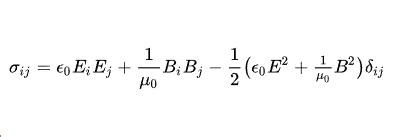
The components of the Maxwell stress tensor as formulated in Wikimedia. Its elements form a square array labelled by i and j that each refer to x, y, z directions and are defined in terms of the components of the electric field E and magnetic field B.  ε0 and m0 are constants in Maxwell's electromagnetic theory, in modern units.

Technical detail

Maxwell has a chapter (no. XI) in volume II of his formative work A Treatise on Electricity and Magnetism entitled On energy and stress in the electromagnetic field. I suspect few people read the Treatise these days, just as few people read Newton's 'Principia', though Maxwell's work is full of insights. He writes the stress in long-winded form and succinctly in quaternion notation, another mathematical concept that needs background familiarity. He points out that stress in general has four consequences, which he quantifies. The first is a pressure in all directions (like that experienced below the surface of a liquid); the second is a directed tension (like stretched elastic - he gives more details); the third is a directed pressure (ditto); fourthly a couple tending to twist every element of the substance (ditto).

Near the close of the chapter he comments: In explaining the electromagnetic force by means of a state of stress in a medium, we are only following out the conception of Faraday, that the lines of magnetic force tend to shorten themselves, and that they repel each other when placed side by side. All that we have done is to express the value of the tension along the lines, and the pressure at right angles to them, in mathematical language, and to prove that the state of stress thus assumed to exist in the medium will actually produce the observed forces on the conductors which carry electric currents. ... We have merely shown that it is possible to conceive the mutual action of electric currents to depend on a particular kind of stress in the surrounding media, instead of being a direct and immediate action at a distance.


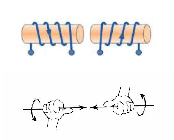
Maxwell tensor diagrams


Diagrams illustrating the use of the Maxwell stress tensor

This gets to the heart of Maxwell's vision. A current is passed through a wire and deflects a compass needle some distance away. Is this 'action at a distance' of the current in the wire? Well if you want to think so, you can, said Maxwell, but you will have a lot of trouble both visualising this and getting the right answer. Maxwell's view is that the wire creates a field everywhere around it (obeying his equations) and the field is stressed. Indeed the field transmits the stress between interacting sources, charges or currents. It gets more interesting. Fig. a in the diagram to the right shows another example: two magnets. Consider an arbitrary surface enclosing one magnet. The force it experiences can be calculated by summing the stress over the surface. Maxwell showed that it doesn't matter what surface you choose, which is a powerful result. (For the mathematical, this comes about by a smart application of Gauss's theorem that converts volume integrals to surface integrals). You can select one surface close to the body or one further away. In practice, the surface of choice is the one for which the mathematics is easiest. Not only that, the problem has been reduced from a problem in electricity and magnetism to one in mechanics. In Maxwell's day, the top physicists were probably better versed in mechanics than they are today, so it was 'problem solved'.

Another implied feature of the Maxwell view is once the field is known we needn't know any information about its sources. In the everyday context of radio reception, we're all extremely familiar with the idea now. Our radio or mobile phone has no idea where the sources of vibrating charge are in the transmitting aerial, only the strength of the electromagnetic field in their vicinity. For historical reasons I've taken the next two images from the great 'Abraham and Becker'. This book, or at least an early incarnation of it authored by Abraham and Föppl, published in 1904, is the one Einstein praised for the insight it had given him. Max Becker may not have been that pleased for he had several public arguments with Einstein over Relativity, which he did not like. The book ran to at least 14 editions under the title Theorie der Elektrizitat and had a lifetime of over half a century. The first image shows field lines coming from two equal charges on either side of the origin. Choosing a surface that is a very large hemisphere (b in the diagram itself) around one charge, the stress everywhere on the surface is a pure pressure (until it fades away in the far distance off the plane shown). Adding it up over the hemisphere the result is just the force expected from Coulomb's law. It is always encouraging to see a general idea give the right answer in special cases. The second figure is the case of equal and opposite charges. In this case the stress is pure tension and upon adding it up the answer is correct.

In many engineering applications, the stress created by magnetic fields is more important than the electrical counterpart. In a non-magnetic medium it consists of a tensile stress of B2/2μ0 along a line of force and a compressive stress of B2/2μ0 in every direction at right angles to the line of force. This is the stress Maxwell was discussing in relation to Faraday's work. Likewise the electric field causes two stresses. If D is proportional to E then these are a tensile stress of DE/2 along the line of force at each point and a compressive stress of DE/2 in every direction at right angles to the line of force at each point.

So powerful was Maxwell's idea of mathematically derived fields permeating all space that fields became the reality of 20th century physics. Einstein introduced the gravitational field characterised by its stress-energy tensor. Today's particle physics recognises a number of short-range fields, like the Higgs field. The characteristic of all fields is that anything that interacts with it, interacts with the field around it, not its source.

References: James Clerk Maxwell, A Treatise on Electricity and Magnetism, 3rd ed'n, Clarendon Press, Oxford, 1892. The 3rd edition is the most likely edition to come across and has been reprinted on at least 4 occasions. The original is out of copyright and a digital version can be obtained from several web-sites. There are 2 volumes.

Max Abraham revised by Richard Becker The Classical Theory of Electricity and Magnetism, 2nd edition 1950 (translation of the 14th German edition of vol. 1 by John Dougall), Blackie & Son, Ltd., London and Glasgow.


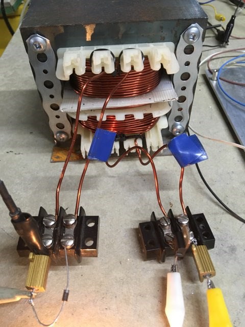
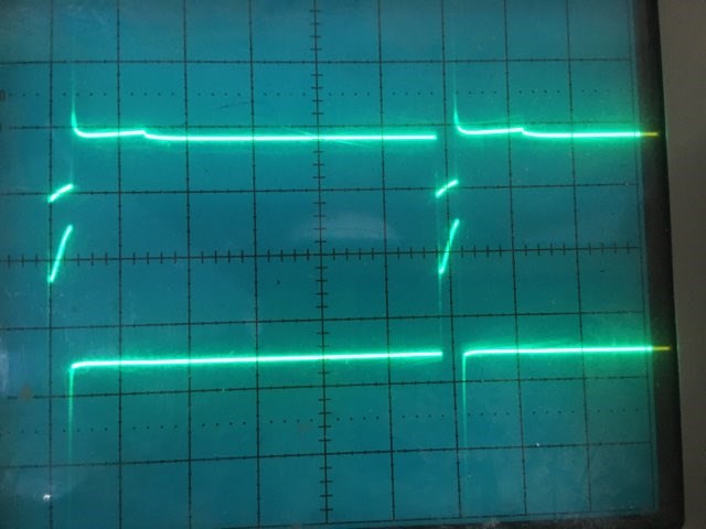
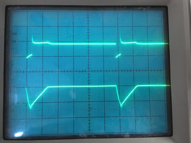
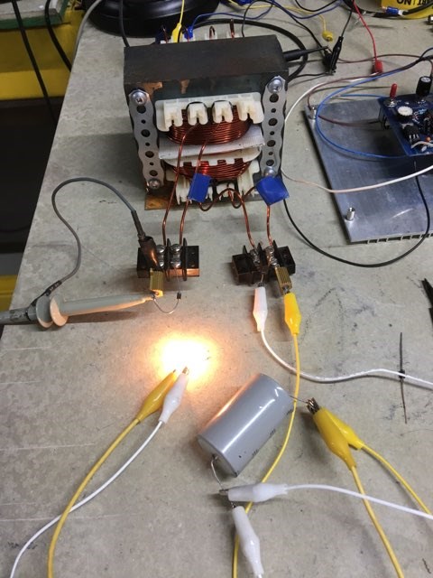
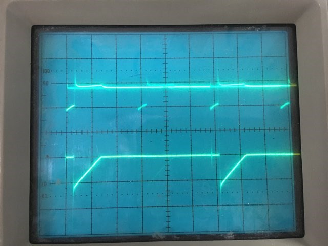
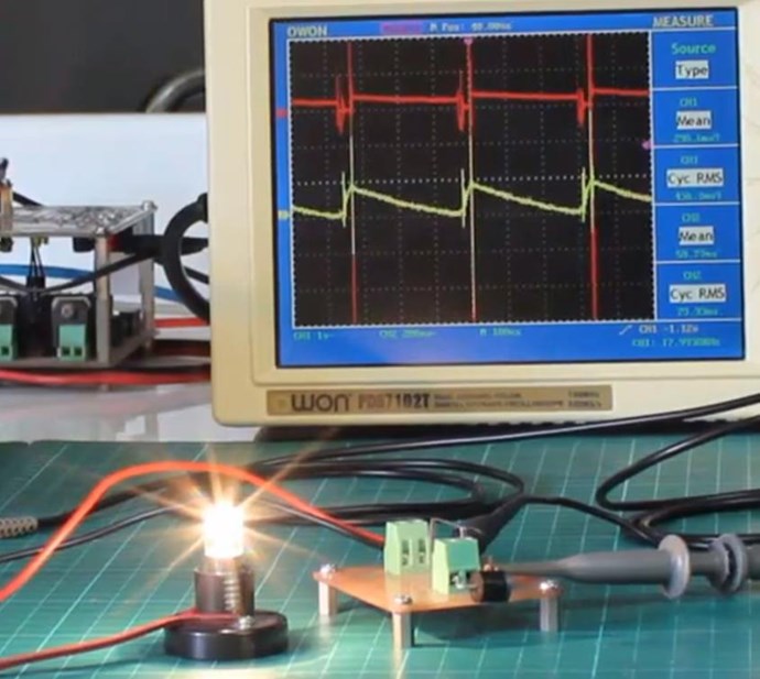
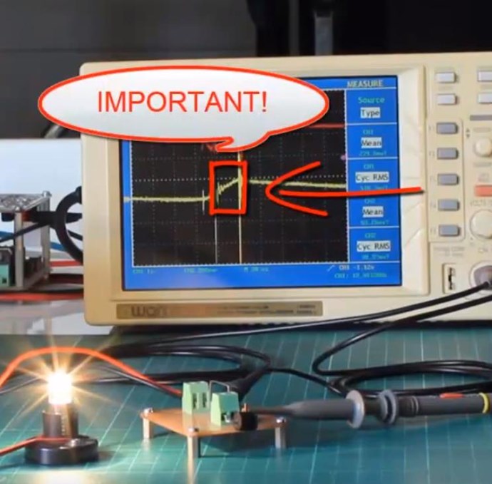
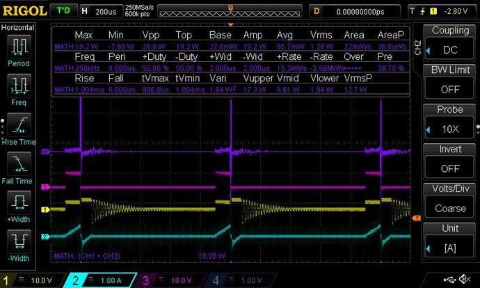
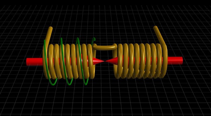
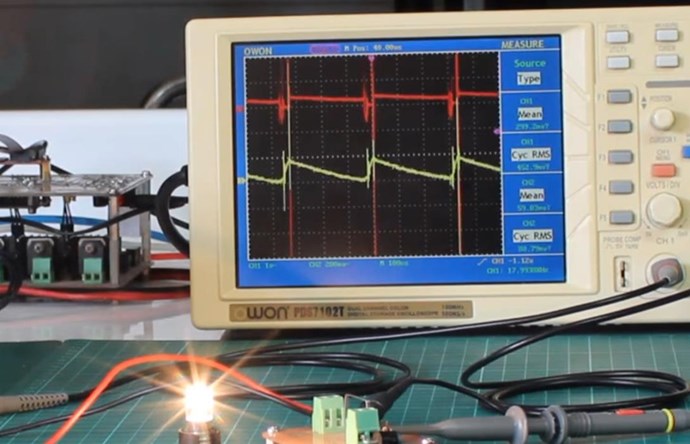
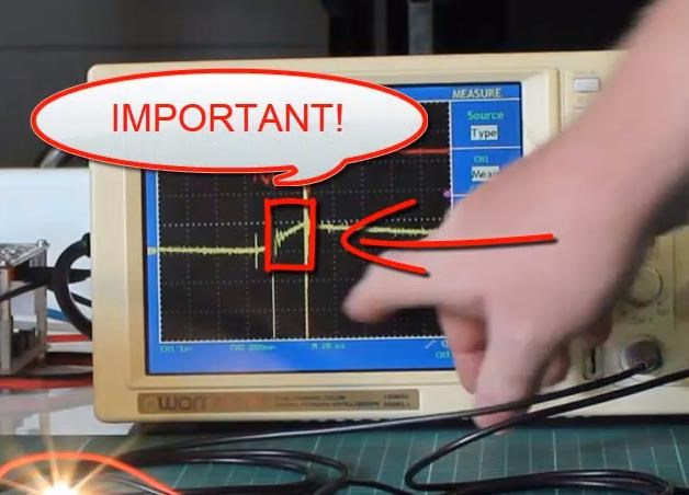
In this case, Bucking Magnetic Fields are a Stress Tensor, by definition, and as a result, the Stress creates a Force, a Magnetic Pressure Force, that gives rise to the Sawtooth waveform.


So we can shorten this us and say, Bucking Magnetic Fields creates the sawtooth waveform, so you're right.

Best Wishes,

   Chris

donovan posted this 09 January 2023

Hi,

Over the last 5 years, I have studied and read a lot of info, by all sorts of people.....Tesla, Moray, Bedini, Lindermann, Sweet, Beardon, Smith, Lockridge, and many more.  I have just started working on the hardware in about the last year, and this lead me here.

Between mis-information, and missing information, I questioned a lot of this info and experimented with the stuff that made the most sense to me.

On this forum, the missing pieces are slowly being fill in.

This all reminds me of tech school, class room theory, that doesn't really makes sense!  Time in the lab to see the theory in action, and then more questions and theory to understand the lab work.

Thank you Chris.


Donovan

Chris posted this 09 January 2023

Hey Donovan,

Your'e most Welcome!

The real trick is, follow the basics, what "Generates" a Voltage, how is it done on the Bench, can you do it, can it be done, because most Researchers are off chasing Total BS that have Zero Bearing in Science, nothing works on the Bench for them, because it cant be done, its Fake Science! That's the Misinformation BS we need to Sweep into the Gutter!

What "Generates" a Voltage is di/dt the Change in Current in the Primary, "Generates" the Voltage in the Secondary. Very simple, very provable, very basic Bench Experiments can prove this:


We just need to take this concept a tiny little bit further, Asymmetrical Electromagnetic Induction, which you are doing on the Bench right now! So congrads to you!

Best Wishes,

   Chris

donovan posted this 10 January 2023

Hi,

Yes, di/dt.

And to wrap my head around the assymetrical regauging......some of my ideas, if you could comment on them..

During the regauge time, we are bringing the magnetic field back up......Voltage.

And we watch the input current, because, if we see it stop changing.....we are wasting power after that......

Ideally we don't need to power the load at this time.....

When the magnetic field (voltage) is back up we can then draw current from the system, with the POC bucking coil also drawing current......

And we watch the L2/D2 and L3/D3 current so we can see the rise in the magnetic field followed by the decay as the magnetic field is collapsing and driving current into the load, with the currents in the POC mirroring each other......

Donovan


Chris posted this 10 January 2023

Hey Donovan,

Will comment within your post:

And to wrap my head around the assymetrical regauging......some of my ideas, if you could comment on them..

During the regauge time, we are bringing the magnetic field back up......Voltage.


Yes: "we are bringing the magnetic field back up" we have Bucking Magnetic Field's, POC Voltage and Current is normally In Phase, no Phase angle, pure Power, the Bucking is between POCOne and POCTwo, so each Coil gains maximum Magnetic Field Amplitude when the Maximum Voltage is reached, because the Potential or Voltage  V / Resistance R = Current I and we have all Coils Loaded, a Current must flow according to Ohms Law! I = V / R


Your Input Coil only controls the Frequency that your Partnered Output Coils operate at! That's all, your input is never loaded, your input Coil see's No Load!


And we watch the input current, because, if we see it stop changing.....we are wasting power after that......


Yes, that's right, we only control the Frequency that your POC Operate at! so any On Time after this is Detrimental to the Machine Operation! It bogs down the Machine!


Ideally we don't need to power the load at this time.....


Correct!


When the magnetic field (voltage) is back up we can then draw current from the system, with the POC bucking coil also drawing current......


These machines are 100% Duty Cycle on the Output, ideally! Only a short Input, normally around 10% but this depends on the Configuration and geometry!


And we watch the L2/D2 and L3/D3 current so we can see the rise in the magnetic field followed by the decay as the magnetic field is collapsing and driving current into the load, with the currents in the POC mirroring each other......


Slap your Hands Together, like you're Clapping, that's what your Partnered Output Coils do!


Listen carefully:


Snaps, or Slaps, either way, you get the idea!


You have the knowledge!

If POCOne and POCTwo both Oppose each other, then one MUST Assist the Input Coil Right! So, if we have Force A and Force B, both are Equal in Amplitude, but one is Negative, then the Vector Sum becomes Zero, no Net Negative Force can react back on your Input Coil because the Forces Cancel! Vectorially! Superposition!

Voltage is either: "Generated" or "Un-Generated", as in the case of the Common Mode Choke!


Voltage is "Un-Generated" by a controlled Impedance! Current through the Controlled Impedance, removes Common Mode Noise by "Un-Generating" the Noise.


Best Wishes,

   Chris

donovan posted this 10 January 2023

Hi,

Thanks for all the direction....

I read somewhere, that it take about seven times of study to really learn something!

Donovan

donovan posted this 01 February 2023

Hi,

Looking for guidance.....

Lately I have been making my test circuit a bit better, and improved my current sense setup.  My next area of investigation, is making power measurements to see what is going on.  I have been reading some of the threads on measurements.  I have everything dialed down while I am learning how to measure power.

A few months before I found AboveUnity, I was presented with the opportunity to purchase this DSO for a really reasonable price.  I always wished for one, but never worried about it.  And had no immediate use for it.  When I found AboveUnity, I knew what the scope was for!

I am thankful for being blessed.......

First real use of the DSO,

Yellow - L1 Voltage

Green - L1 Current (0.1 ohm)

Blue - L2 Lamp current

Pink - L3 Diode current

Current sense boards with 0.1 and 0.01 ohm resistors and a voltage test point.

Next step is to figure out the math on the scope for power measurements.

Any input is appreciated.

Donovan


  • Liked by
  • Chris
  • Augenblick
Chris posted this 01 February 2023

Hi Donovan,

Where you show:

Pink - L3 Diode current


That's looking good, but you need more turns on your POC. This is to get your Voltage Up, as Voltage goes up, Current must also go up: I = V / R, if R stays the same.

Bucking Coils Pump Current from Source, the Atom, Electric Charge, being Electrons / Ions, and Current is the velocity of these 'Fundamental' Charges. As Voltage Potential goes up on your Partnered Output Coils, they work more efficiently.

Please Note: A shorter Sharper Input Pulse is also a way to get your POC Voltage Up! I have not yet covered this in great detail, only partially.

There may be a problem with polarity, the Blue Trace does not look right.

Also, The Input Coil is not quite right:


Try to improve there, because it should be sending power back to the Input. See the provided link.

Best Wishes,

   Chris

donovan posted this 02 February 2023

Hi,

Thanks for the input.  I will keep on it.  Tonight I re worked my transformer a bit, increased the turns on the POC.  I will test it tomorrow night.

I was looking at trace 3 as well, I was wondering if my diode speed is too low.  The trace is 100us per div.  I did notice in a previous experiment, the diode speed of L3/D3, did affect the rise time of the L1 current.

On the input coil, I am using a low side driver.  I wonder if it would be easier to understand if I switched to a high side driver.  As well, I made a mistake, my current sense resistor is 0.2 ohm.  This may be influencing the Voltage waveform.  I should switch to a 0.01 ohm.

I gave up on MSM anything, 2-3 years ago, so now I listen to podcasts on the commute.  I was listening to the series on "Simple steps to above unity".  You mention in one passage that these eternal flashlights seemed to have one winding 1/4 the turns of the other.......have you heard of an RF concept called the "1/4 wavelength transformer"?

Thanks for all you help.

Donovan

Chris posted this 02 February 2023

Hey Donovan,

You're doing really good My Friend! Stick at it, and study with direct focus on the Partnered Output Coils:

  • Why they have to Oppose using the Right Hand Grip Rule.
  • Why the Currents must create Opposing Magnetic Fields.
  • Why the Magnetic Fields Oppose.
  • What's the point of POC Fields Opposing?
  • Why does Opposing Magnetic Fields "Generate" Electrical Energy.
  • The Magnetic Capacity gained during the TOn Time is important! Why?
  • How the Current is "Pumped" - This is Important!


Stick at it, you're got a really good grasp of this!

I have a Demonstration I am thinking about releasing soon. We are nearly at: "Go Time"!

We have Identified many Trolls and Disinformation Shills, they will Pay a very Heavy Price when this is done!

Godspeed My Friends!

Best Wishes,

   Chris

donovan posted this 05 February 2023

Hi,

Looking for comments.

This forum is handy for keeping track of experiments and progress!  This mornings experiments:

I added more turns to my POC, so 72T on each now with 12T in my L1.  I added the 15000 uf, 1uf, and .1uf bypass capacitors at the MOSFET/L1 circuit.

Analyzing this scope shot, I have some ideas come to mind for the next experiment.......

Yellow - MOSFET/L1 Voltage.

Green - L1 Current

Blue - L2/Lamp Current

Pink - L3/D3 Current

I am finding a process for getting things "tuned".......I start with a low frequency/ low duty cycle......(I can vary the on time and off time independently)......Adjust the on time for a maximum pulse width that allows for a continuous rise in current.....then raise the frequency to have the L3/D3 current approach a perfect sawtooth waveform.  The fine tune the On time to give a nice looking L2/Lamp current.  The fine tuning of the On time seems to have a great influence on the frequency/phase of the high frequency magnetic resonance.

Next I would like to try a High Side driver, exchange my L2/L3 circuits, contemplate the physical layout of my transformer and learn the math on this new (to me) scope.

I also thought I would sweep one of my current sense resistors with the Vector Network Analyzer. 

Teal - Insertion loss (less than 1 dB below 100 mHz)

Yellow - Return Loss (Mismatch), (less than 10 dB below 100 mHz)

No funny resonances below 100 mHz, I think it is acceptable.

Donovan

Chris posted this 05 February 2023

Hey Donovan,

Also, The Input Coil is not quite right:


Best Wishes,

   Chris

donovan posted this 09 February 2023

Hi,

I am looking for feedback on today's learning.

The first four photos are VNA sweeps of the POC and one random coil for comparison.  I am approaching this with a background in RF.........

A random coil for comparison.  One point of resonance as indicated by the Insertion loss (teal trace) response, in the parallel resonance mode.

L1 response, two points of resonance on the Insertion Loss trace.......wasn't expecting this.....

L2 Sweep

L3 Sweep, ,similar to L2, I was not expecting this response, after sweeping a random single coil I realized, L2 and L3 are not identical.  If they were identical, the traces would be show a single resonance point......where here they show two......something for me to investigate.....my build quality, L2 influenced by L1.......I have seen this response lots in the RF world where we wish to increase bandwidth......coils in a a system have slightly different resonant frequencies.......but here, I think we want them to be the same.......

My latest experiment, a small but noticeable change.  I rewound L1 to have the same number of turns, but a higher inductance, and a looser coupling to L2/L3.  It appears this resulted in a more pronounced high frequency resonance, and a stable L2 current.  I am running into physical constraints as to how lose I can make the coupling between L1 and L2/L3.  But I will investigate on how to have L2/L3 resonant on the same frequency and at the same time try and have a loser coupling to L1, for the next experiment.

Donovan

PS.....After reading Chris's latest post about MOSFET Drivers, I think I also have to upgrade my MOSFET as it has a Vds of 200V and I think I am running into this as a limiting factor when it avalanches from the high resonant voltages.


donovan posted this 11 February 2023

Hi,

Some more of my observations, looking for feedback.

In my experiments with the POC and trying to get more magnetic resonance and an improved saw tooth waveform, I noticed;

Before changes:

The saw tooth wave form had a rise time, regauging period, and a longer fall time followed by a "flat line" before the next regauging period.  The fall time and the flat line were about the same length in time.

Changes; I added about 25% to the number of turns on the POC.

I noticed the period of the flat line became shorter, so I have concluded the optimum turns ratio will give a better saw tooth wave form.

Thinking about this brings up a question in my mind, something to investigate at some point in time.......in this science, is there a relationship between core material and optimum turns ratio?  Or maybe, more than likely, the other way around, with the optimum turns ratio, we get the best magnetic energies, resonance for the core material......

Donovan

Chris posted this 11 February 2023

Hey Donovan,

Would be great to see Pictures and Videos, so we can see what your progress is.

Very hard to tell other wise.

Best Wishes,

   Chris

donovan posted this 11 February 2023

Hi,

Any input is appreciated!

L1 = 12T, L2/3 = 60T.  L1 is one layer tightly wound on L2.


L1= 12T, L2/3 = 72T, L1 tightly wound on L2.


L1=12T, L2/3=72T, L1 = a 1mm layer of cardboard was placed over L2, and then L1 was wound using two layers of 6T to provide for a looser coupling between coils.

By increasing my turns ratio and having 72T on L2/3 it seems the deadtime prior to the re-gauging period has been halfed, comparing the first photo to the second.  I have tried a variety of frequencies, and that seem to have a minimal effect on this dead time.

By providing looser coupling of L1, in the third photo, it seems to have allowed for much more resonant voltages.

I am observing lots, and these experiments are bringing back a lot of the stuff I had seen in the RF world.  I sure hope I am sort of headed in the right direction.

With the wire gauge I have used and the coil forms, I am at the limit of how many turns I can put on.  I think I may get another coil form and use thinner wire to allow me to experiment more with the turns ratio.  Or, first, maybe I will reduce the turns on L1 and see what effect that has.  And as well I will switch to a higher voltage MOSFET.

Donovan

Chris posted this 11 February 2023

Hey Donovan,

Thanks for the scope shots, this helps somewhat. However, I see no change from some of the other scope shots that were provided in prior posts.

Some scope shots are a long ways away from what they should be! The Pink trace is close, but can not be right, because the others are very far off: Purple trace is very far off! Your purple should be like my Red!


Maybe a review of my earlier experiment:


Wise words from Don Smith:


POCOne and POCTwo are configured in Bucking / Opposing Mode via the Diodes and L1, your Input Coil, is only to bring your Partnered Output Coils into Magnetic Resonance. A Resonance where the Change of Magnetic Field B, ΔB is sufficient to produce the same Voltage V, in the Opposing Partnered Output Coil.

Just like Paul Raymond Jensen said:

An alternate explanation for the current gain in the UDT is to consider each secondary winding as acting as the primary winding for the other secondary winding when an output current is drawn because the two secondary windings generate geometrically opposing fields.


I hope this helps! Its just the way we think about this.

Best Wishes,

   Chris

donovan posted this 12 February 2023

Hi,

Thanks for all the info......I will continue...

Donovan

Chris posted this 13 February 2023

Hello Donovan,

This is very, very easy Donovan, Very Easy. Turning the Conventional Symmetrical Transformer into an Asymmetrical Transformer. Utilising the Secondary Coils Magnetic Field changing over time, to 'Generate' another E.M.F that normally would be ignored!

Best Wishes,

   Chris

donovan posted this 14 February 2023

Hi,

Thanks for all the encouragement, Chris.......at some point, it will all just, "click".

Here are a couple shots of today's experiments.

What do you think?


In tonight's experiments, I started with a 12V 10W bulb, and that wasn't too bright, then I switched to a 12V 3W bulb, that worked better.  Then I thought, with fewer turns on L1, maybe I needed a higher impedance load on L2, so I tried a 120V 7W bulb, and that worked pretty good.  Then I thought, I would try a 120V 40W bulb, that worked, good.......then I thought, lets turn up the duty cycle bit, and before I knew it, the bulb blew up and I had sparks on L2........I had my I/P PS limits set for 2A and 20V.......40W max......

Donovan

Chris posted this 14 February 2023

Hey Donovan,

Pink Trace and Blue Trace are good, you have the Effect there, the Pumping of Current! If you study this, exactly what you have, and understand it, you will be running your house from these machines before you know it!

Input Traces are still not right.

Voltage Potential on the Prink and Blue Trace, how to increase the Potential and Why?

Best Wishes,

   Chris

ISLab posted this 15 February 2023

Hi Donovan,

With the wire gauge I have used and the coil forms, I am at the limit of how many turns I can put on.  I think I may get another coil form and use thinner wire to allow me to experiment more with the turns ratio.  Or, first, maybe I will reduce the turns on L1 and see what effect that has.  And as well I will switch to a higher voltage MOSFET.

@Everyone, please feel free to correct me if I'm wrong.

From what I understand, the turns ratio is only relevant for transformer effects. Here we are dealing with antenna theory, so length is much more important than turns!

Get the L2 and L3 the exact same length, including the leads; then get the L1 to be exactly 1/4 of L2.

Wind L2 and L3 to be exactly the same (same turns and same layers) but switching directions CW to CCW, and same leads lengths.

The only point where turns ratio will matter is between L1 and L2, and even then the impedance ratio will matter more.

Chris posted this 15 February 2023

Hey ISLab,

First and foremost, the effects.

Second, apply the general principles to try to improve the operation of the machine.

Don't get tied up in details that may not suit you and your machine! Listen to your gut and what your machine wants.

Best Wishes,

   Chris

Melendor posted this 15 February 2023

Hello IsLab.
I am also looking for answers to that question for 2 years.....but did not found them.

""" From what I understand, the turns ratio is only relevant for transformer effects. Here we are dealing with antenna theory, so length is much more important than turns!""

What I did find is that :

L1 and L2 work in the transformer Mode , not antenna theory.
That means , that if you got 5 Turns L1 and 150  Turns L2 , that will be a STEP UP Transformer , and the Current in L3 will be like 0.
The change in Current over L2 , puts a Voltage on L3 and a current will flow in it.
(that means, that if you do NOT have a Current in L2 , you will not get an magnetic field on L3 )
In other words the ratio L1-L2 , must be close enough that it will trigger current in L3.

I tried 1 Turn L1 , 5 Turns , 10 Turns , 20 Turns etc. The more turns on L1 , the better it worked for the load.

All your questions are very good ,however the TOP question that we must find an answer to is :

UNDER what conditions , does L3 help the INPUT ? 
I say this because I have lots of current in L3 , but it does not talk with L1 , it doesn't matter how i place the diode on it , the Input remains the same.

This are my 2 cents about the situation buddy.
Keep experimenting,and one day we will get it Right !

Stay safe !
~~~Melendor the Wizard

Chris posted this 15 February 2023

Hello Melendor,

I disagree with everything you have said!

I am also looking for answers to that question for 2 years.....but did not found them.


I disagree, and to be honest, I see an over complication, where none should exist!


All devices are different, not one will be "Exactly" the same! So no Rules should be set out, or expected, when there are none! One can not find, what does not exist!

What I do see, is some people signing up fake accounts ( CD_Sharp ), coming here, causing trouble, making an effort to confuse others, and creating problems where there are none!

What should be occurring:

  1. Build the Machine as I have laid out.
  2. Study the Effects, until  the Effects are Understood.
  3. Make steps to improve these same Effects!


I get really tired of Trouble makers! I get really tired of those coming here causing trouble! It is so obvious who is here to help and who is not!

I have Banned so many Morons, because they have no idea what so ever! I don't want to keep banning people! I want people to get it! I want people to realise, and gain an understanding of the most simplest thing the world has missed for over a Century!

One Hundred Years, people have chosen to stay Dumb, and this is SOOOOOO Fricken SIMPLE! How about we tell our inner Guru to Shut up and try to learn from our Instinct for a while?

UNDER what conditions , does L3 help the INPUT ? 


If your POC Oppose, are BUCKING, then one MUST Assist your Input Coil, there can be no other way! VERY SIMPLE!!!

It so angers me how some people argue with Simple Logic!

And the Other Forums keep Ooooozing Dumb Nothingness!!!

Best Wishes,

   Chris

donovan posted this 16 February 2023

Hi,

All the info from everyone's experiments is good. 

And yes, sometimes we make things too complicated!  And I think we need to keep in mind......when this technology was discovered by people like Hendershot......they had almost no resources compared to what we have......

The last couple evenings efforts involved, beefing up my MOSFET wiring, rewound L1 with heavier wire, changed my L1 current sense resistor to a 0.01 ohm, made all my diodes the same, and added a diode across the MOSFET.

It was getting late.......but.....

I now see a negative current pulse on my L1 current sense resistor, it is narrow, but a very large amplitude.

Donovan


donovan posted this 19 February 2023

Hi,

I have been spinning my wheels here, for a couple days......then this morning I figured out I had a shorted D2.

So, I am looking for comments on the latest waveforms......

Yellow, L1 Input Voltage from low side MOSFET Driver

Green, L1 Input current. 0.01 Ohm

Blue, L2/D2 current. 0.1 Ohm

Pink, L3/D3 current. 0.1 Ohm

Yellow, L1 Input Voltage from low side MOSFET Driver

Green, L1 Input current. 0.01 Ohm


Donovan

PS......one thing I am curious about is that small falling spike, about 1 uS before the large current change on the second photo.....

Chris posted this 19 February 2023

Hi Donovan,

Can you explain this:

then this morning I figured out I had a shorted D2


I have no idea what you mean by this, it is supposed to be shorted, so you have made a statement that makes no sense?

Your Waveforms have gone backwards, they are not as good as they were.


Perhaps you have not understood what was required? There is much more to this than what the average person can realise! Its very Simple, but only once understood!

Best Wishes,

   Chris

  • Liked by
  • Augenblick
  • Plasmonic
donovan posted this 19 February 2023

Hi,

D2, failed.....

I will have to review my past experiments.

......A short pulse into L1, with a changing current to create a magnetic field, thus Voltage on the POC coils, which will provide opposing currents, opposing magnetic fields to each other, one of which will aid L1.......now, the "mechanics" of this, I guess I haven't figured out yet......

So, reading back in these posts, (they are a handy way to record what I have done), from the last image of mine, you posted, it looks reasonable, but higher potentials would be good on the blue and pink traces....these potentials, depend on the magnetic field.....which depends on the di/dt of L1.......which means more current (change) and/or less time for that change......

Feedback, please.....Thank you....

Donovan

ISLab posted this 19 February 2023

D2, failed.....

Perhaps you mean to say that your diode D2 was internally shorted?

From excess voltage or current? Which diodes are you using and what is the voltage spike like? What is the current like?

On a personal note, please don't worry too much about going back and reviewing. You seem to be on the right track. Just make the corrections and move on.

donovan posted this 19 February 2023

Hi,

Thanks for the encouragement, ISLab.  I think the diodes I grabbed from my supplies, were a DTV1500, 1500V, 6A, 135 nS.

Yes, when I up my Supply Voltages a bit, 15-20 VDC, the peak voltages and currents can get crazy, especially after I beefed up my wiring around the MOSFET and L1

Thanks,

Donovan

ISLab posted this 19 February 2023

The guideline from Chris which I found very helpful is to keep your voltages low initially and focus on the effects. Once you have them stable, only then raise the voltages.

In my experience, I needed at least 7V on the pulse (but not more than 12V) to overcome internal resistances and impedance and get good results.

What are you using to pulse the MOSFETs? Do you have a driver?

Since you seem intent on long-term experimentation, I would highly recommend starting to build the RFSS, so that by the time you have useful results, the RFSS will be ready for deep-dives. In the long run you will save yourself lots of problems with circuits and components failing. Consider also purchasing AMCC cores now so that you have them ready when needed.

Chris posted this 19 February 2023

Hi Donovan,

These waveforms are heading in the right direction:


You need to stick at it and not change things, moving away from what you have achieved.

These waveforms are heading in the wrong direction:


These are just flyback waveforms and not right.

Best Wishes,

   Chris

donovan posted this 20 February 2023

Hi,

Tonight's experiments....

Yellow, L1 Voltage, low side MOSFET Driver

Green, L1 Current, 0.01 Ohm

Blue, L2 Current, 0.1 Ohm

Pink, L3 Current, 0.1 Ohm

I think I am back, where I was a few days ago.....

Thanks for all the feedback.

Donovan

donovan posted this 23 February 2023

Hi,

Are the following wave forms closer to the direction I need to go?


Yellow L1 Voltage, Low side MOSFET Driver

Green L1 Current

Blue L2 current

Pink L3 Current

Any feedback is appreciated

Donovan

Chris posted this 23 February 2023

Hey Donovan,

Yes, this:


Is very good! You have all the indicators that your heading in the right direction! This is by far the best you have produced so far!

We see Positive Voltage, and also a Negative Current starting to become more predominant on your Input Traces! This is super important!

Your Output is looking good! A bit Curvy but hey its a Plus to have Amplitude on each Trace! Perhaps there is a bit of Capacitance on the Load? I use a Linear Resistance, as a Load. 

PLEASE: I urge you to study this in more detail, understand this fully, study the Input Pulse, Duty and Amplitude, and you will gain a knowledge where it wont be long before you're powering your House from your Energy Machine!

Best Wishes,

   Chris

donovan posted this 24 February 2023

Hi,

Thanks for the feedback, Chris.

The last little while, I have been tuning to get some power output, but never really saw the wave forms like yours.  I was thinking for a while, I am just building really efficient SMPS's.  And I keep thinking about the POC's bucking each other, and never really saw anything that made sense to me.  Then I thought, lets tune and see if I can get a waveform, and not worry so much about power out.  And this is where I ended up.

So, your thoughts on my next statement?  I studied these wave forms for a long time.

"In the photo above I think the most important aspect (that I need to concentrate on) in the POC theory, is the 20 us right after the Low Side MOSFET Driver turns on.  We see a steep rise time in the input current.  We see similar rise times in L2 and L3 currents.  If these current ramps continued for the entire duty cycle, it would probably do wonders."

Donovan

Chris posted this 24 February 2023

Hi Donovan,

I would disagree, this image is almost exactly like my waveforms:


and your waveforms here, indicate Power on the Outputs, plural. Anything above or below the Zero Graticule Line is Power, or at least a Potential.


So, I think you now need to think about where this power is coming from, its not the Input Coil is it?

What is your Input Coil doing to your POC?

Best Wishes,

   Chris

Chris posted this 25 February 2023

My Friends,

By carefullt studding the Waveforms Donovan has shared, we can see something quite remarkable:


I asked the question:

What is your Input Coil doing to your POC?


So: What is your Input Coil doing to your POC?

Can you see something remarkable like I can? Can you see a Coil, POCX doing something quite amazing?


What is occurring here? What is the Potential doing on the Traces? Why does the Blue and Pink Trace go negative very fast? Below the Zero Graticule Line!

What's the Slope on the Traces I have Pointed out? Why is that there? We have spoken of: Rise over Run now for a long time. So what's this Slope that has a Rise and a Run?

Best Wishes,

   Chris

donovan posted this 25 February 2023

Hi,

I haven't done much in the lab the last couple days......busy cleaning up the garage before the farming season starts, and I would rather be outside!!!

And I have been thinking about what the next step should be.

I have been studying these last couple scope shots, though.

I believe......those 10-15 microseconds of trace that you pointed out.......that is what we are after........this is when the POC are actually creating their two opposing fields that are bucking.......they are in resonance......they are opposing......the net circuit impedance is minimum.......currents are maximum.......rise times are at their peak.......I need more of this.

To take it one more step......I need POC L2, the blue trace to have more stored energy at that instant, to continue the bucking for a longer time period.....When the blue trace runs out of steam, and goes to zero (flat line), that is the end of the actual bucking action.....

Any feedback is welcome.

Donovan

Chris posted this 25 February 2023

Hey Donovan,

You say:

Any feedback is welcome.


All your answers lay here, on this forum! 

We have covered everything right here! Every Detail you need to move to the next step! Its all in:

 Start Here → Builders Guide to Aboveunity Machines


So, at the moment, your next step is; Study the waveform further, find out why you see the Rise over Run, the Slope or Gradient, and why the Blue and Pink Traces drop Negative so fast!

Yes, you are correct:

more stored energy at that instant, to continue the bucking for a longer time period


The total Bucking Force, the Stored Energy of Each Opposing Field is dependant on what?

The Magnetic Field: 1/2 LI2

  • Turns N
  • Current I
  • Inductance, which is derived by the Turns and Current: L = VL /  Δi / Δt


Where: L is the inductance in Henries, VL is the voltage across the coil and Δi / Δt is the rate of change of current in Amperes per second, A/s.

and Current I is dependant on what: I = V / R

  • Voltage V
  • Resistance R


and what is Voltage dependant on: ΔΦB / Δt

  • The Time Rate of Change ( Δx / Δt ) of the Magnetic Field B ( ΦB )
  • Turns N
  • Cross Sectional Area CSA


Do you see a Loop here that one step follows the other?

The Other Forums have no idea!

We are Light Years Ahead of the Other Forums!

Best Wishes,

   Chris

donovan posted this 26 February 2023

Hi,

Thanks!

Donovan

Chris posted this 26 February 2023

Hey Donovan,

When I said:

and what is Voltage dependant on: ΔΦB / Δt

  • The Time Rate of Change ( Δx / Δt  of the Magnetic Field B ( ΦB 
  • Turns N
  • Cross Sectional Area CSA


You realise this is the very same ΦB of the opposite Partnered Output Coil? Thus the Loop of Feed Forward and Feed Back occurring?

The Magnetic Field: 1/2 LI2

  • Turns N
  • Current I
  • Inductance, which is derived by the Turns and Current: L = VL /  Δi / Δt


Where: L is the inductance in Henries, VL is the voltage across the coil and Δi / Δt is the rate of change of current in Amperes per second, A/s.

and Current I is dependant on what: I = V / R

  • Voltage V
  • Resistance R


and what is Voltage dependant on: ΔΦB / Δt

  • The Time Rate of Change ( Δx / Δt  ) of the Magnetic Field B ( ΦB  )
  • Turns N
  • Cross Sectional Area CSA


Initially, this can be some what 'difficult' to wrap ones head around, because its not taught, its not accepted by any institution or authority, due to ignorance and stupidity, but right there on the bench, you have exactly this occurring, if you study this and take advantage of the Resonant 'loop'.

Your Input Coil see's no Negative Forces! It becomes free, only to regulate the Frequency at which your Partnered Output Coils Operate.

Best Wishes,

   Chris

We're Light Years Ahead!
Members Online:

No one online at the moment


What is a Scalar:

In physics, scalars are physical quantities that are unaffected by changes to a vector space basis. Scalars are often accompanied by units of measurement, as in "10 cm". Examples of scalar quantities are mass, distance, charge, volume, time, speed, and the magnitude of physical vectors in general.

You need to forget the Non-Sense that some spout with out knowing the actual Definition of the word Scalar! Some people talk absolute Bull Sh*t!

The pressure P in the formula P = pgh, pgh is a scalar that tells you the amount of this squashing force per unit area in a fluid.

A Scalar, having both direction and magnitude, can be anything! The Magnetic Field, a Charge moving, yet some Numb Nuts think it means Magic Science!

Message from God:

Hello my children. This is Yahweh, the one true Lord. You have found creation's secret. Now share it peacefully with the world.

Ref: Message from God written inside the Human Genome

God be in my head, and in my thinking.

God be in my eyes, and in my looking.

God be in my mouth, and in my speaking.

Oh, God be in my heart, and in my understanding.

Your Support:

More than anything else, your contributions to this forum are most important! We are trying to actively get all visitors involved, but we do only have a few main contributors, which are very much appreciated! If you would like to see more pages with more detailed experiments and answers, perhaps a contribution of another type maybe possible:

PayPal De-Platformed me!

They REFUSE to tell me why!

We now use Wise!

Donate
Use E-Mail: Chris at aboveunity.com

The content I am sharing is not only unique, but is changing the world as we know it! Please Support Us!

Thank You So Much!

Weeks High Earners:
The great Nikola Tesla:

Ere many generations pass, our machinery will be driven by a power obtainable at any point of the universe. This idea is not novel. Men have been led to it long ago by instinct or reason. It has been expressed in many ways, and in many places, in the history of old and new. We find it in the delightful myth of Antheus, who drives power from the earth; we find it among the subtle speculations of one of your splendid mathematicians, and in many hints and statements of thinkers of the present time. Throughout space there is energy. Is this energy static or kinetic? If static, our hopes are in vain; if kinetic - and this we know it is for certain - then it is a mere question of time when men will succeed in attaching their machinery to the very wheelwork of nature.

Experiments With Alternate Currents Of High Potential And High Frequency (February 1892).

Close