Magnet Conditioning in the Sweet VTA — what a thermal-magnetic process can and cannot store, and where the same process already exists in industry
Prepared for the Floyd Sweet VTA — Partnered Output Coils thread on aboveunity.com.
0. Scope, and why this is worth reading even if you think conditioning is a myth
The thread has two positions on conditioning. One says the orthogonal coils will not produce output unless the magnet has been conditioned. The other says conditioning is a distraction that Bearden attached to the device afterwards, and that the machine is explained by asymmetrical induction and by the way the output coils are wound and loaded.
This document does not try to settle that by argument. It does three things instead:
- It states what the numbers demand of the device, from the two documented versions.
- It separates what a heat-and-field process can store in a hard ferrite from what it cannot, with the arithmetic shown, so the claim becomes testable instead of a matter of belief.
- It lists existing industrial and laboratory processes with exactly the same structure — heat, apply a field, cool under that field, lock a state — with references. None of them are free-energy sources. They are ordinary materials engineering, used in production today.
The conclusion is in the middle of the two camps, and it is falsifiable: a thermal-magnetic process can lock a threshold, a symmetry, a switching depth and a response band. It cannot lock a clock at 60 Hz or 400 Hz. If that is right, conditioning is real but it is not what most of the retellings say it is, and the frequency belongs to the loop — magnets, coils, load — which is the position the engineering side of this thread already argues from.
Nothing below asserts where the energy comes from. That question is deliberately left open; the material here stands or falls on measurements either way.
1. Two versions of the device. Do not mix their numbers
Almost every contradiction in the Sweet literature comes from mixing these two.
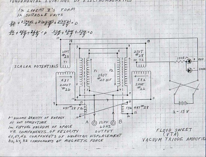
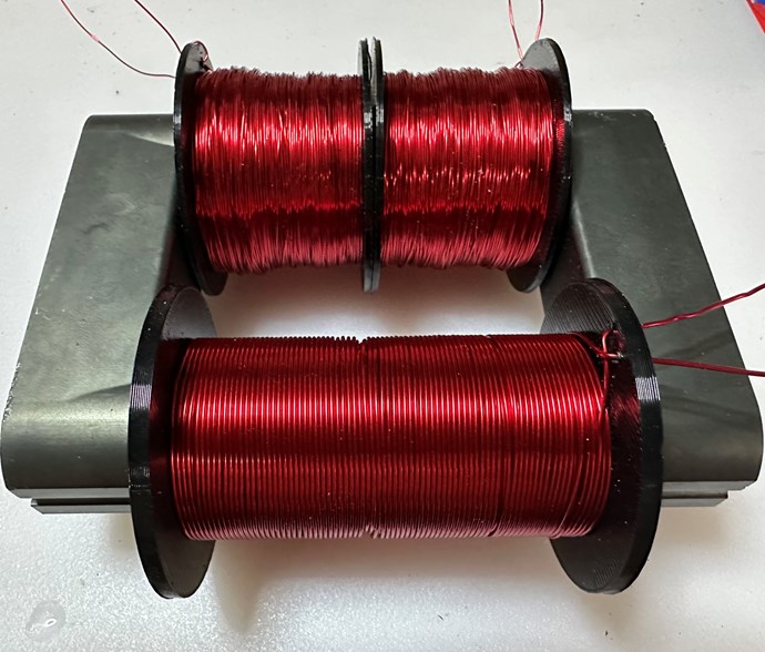
- 1986, transcribed lab notes: Plates: 1″ × 4″ × 6″ ceramic; Field between plates: "500+ gauss"; Output coil: 12 turns of #12 on a 1.5″ form; Drive coil: 250 turns of #18, orthogonal; Input: 7 V × 143 µA ≈ 1 mW; Output: 24.2 V × 4.6 A ≈ 111 W; Frequency: ~400 Hz; Capacitor: explicitly "not a capacitor, no resonant effects"; Thermal: ran 10 hours without heating; Mass: —.
- 1991, Sweet–Bearden report: Plates: 4″ × 6″ × ½″ in most retellings; Field between plates: —; Output coil: not published; ≤300 turns is the only figure compatible with the stated mass; Drive coil: orthogonal; Input: 330 µW quoted in retellings; Output: >1 kW claimed; Frequency: 60 Hz (also built for 50 and 400); Capacitor: not stated; Thermal: ran cold; frost on shorting; Mass: 6 lb, weight reduced by 90 % at 1 kW.
Two details from the 1986 notes deserve attention because they are measurements, not recollections:
- The drive coil's apparent impedance in the assembled machine was hundreds of kilohms, against 2–3 Ω on the bench. That is not a property of the coil; it is the valve pushing back into the trigger. At 143 µA this corresponds to roughly 7 V of induced back-voltage on the drive winding, i.e. the magnetic state is swinging on its own and the drive is only timing it.
- Sweet notes that the magnet size is secondary to the coil volume. That is a strong hint the plates set the bias and the coil volume sets the throughput.
Source for the notes: transcribed lab notes, hyiq.org.
2. What the numbers demand
Three constraints fall straight out of the documented figures, and any model — conditioning or no conditioning — has to satisfy them.
2.1 The flux swing must be comparable to the whole magnet flux, not a few domain walls.
For 120 V at 60 Hz the required flux amplitude is Φ = U√2 / (2πf N). With a few hundred turns over the plate area this lands at 0.04–0.10 T of swing, against a static field between the plates of the same order (measured over the plate area, not on the axis: about 30 mT for ½″ plates, about 52 mT for 1″ plates; on the centre line alone you get 41–72 mT, which is why axis-only estimates flatter the design). Same conclusion from the 1986 numbers by a different route: 111 W at 400 Hz through 12 turns requires a swing at least as large as the magnets' own flux.
So: whatever modulates the flux has to move most of it. Reversible domain-wall wiggle in a hard ferrite gives percent-level changes. That is two to three orders of magnitude short. Any mechanism proposed here has to be a switch, not a nudge.
2.2 The drive cannot be the source.
250 turns at 143 µA produce, in a 76 mm gap, a field of order 0.5 µT — about 0.001 % of the working field, and a per-cycle energy about a million times below the output. Whatever the drive does, it triggers; it does not deliver. This is the one point on which every position in the thread already agrees, and it is worth stating numerically because it constrains everything else: a trigger that weak can only work on a system sitting on a threshold.
2.3 The output coil's own impedance decides whether a capacitor is needed.
For the 1986 coil — 12 turns, 1.5″ form — the inductive reactance at 400 Hz is negligible, the power factor is essentially unity, and Sweet's "no capacitor, no resonant effects" is consistent. For a several-hundred-turn coil at 60 Hz the reactance is tens of ohms, the phase angle becomes large, and the machine would need compensation. This resolves an apparent contradiction in the literature: both "no capacitor" and "needs a tank" are true, for different builds.
It also matters for the switching argument in §3: with a large phase angle, the load current is still flowing at the moment the flux reaches its extremes, and the coil field then opposes the switch. Near unity power factor, the load current is zero exactly when the flux turns over.
3. What a heat-and-field process can and cannot lock into a hard ferrite
3.1 What it can lock. Cooling a ferrite through a temperature range while a field is applied changes, permanently, the state the domain structure settles into:
- a stabilised wall position — ionic and vacancy rearrangement around a domain wall digs the wall its own potential well (this is the same physics as disaccommodation / magnetic after-effect, a standard and unwanted property of soft ferrites, exploited deliberately here);
- an induced uniaxial anisotropy — magnetic annealing, used in production to square hysteresis loops;
- a bias point held by the partner magnet, if the pair is cooled together in the final geometry;
- a bistable configuration — a state which, once pushed past a threshold, flips as a whole rather than proportionally.
The last item is the important one, because §2.1 demands a switch. And bistability of exactly this kind is manufactured on an industrial scale — see §4.5.
3.2 What it cannot lock: a clock.
The popular version of the story says a frequency is written into the magnet. Run the arithmetic. Thermally activated relaxation gives a response time τ = τ₀·exp(E/kT). Take the standard attempt time τ₀ ≈ 10⁻¹² s. Then at room temperature:
- 12 Hz | 0.60 eV
- 60 Hz | 0.56 eV
- 400 Hz | 0.51 eV
Two observations, and they cut in opposite directions.
*In favour of conditioning: the whole span from the reported 12 Hz treatment rate to the 400 Hz running frequency fits inside 0.09 eV, a single family of ionic hops in an oxide. The width of that band is independent of the assumed attempt time — it cancels. So the claim "the treatment prepares a population of centres whose response lies in this band" survives the arithmetic.
*Against the strong version: the absolute barrier does not cancel — change τ₀ by three orders of magnitude and every number in the table moves by ±0.06 eV. Worse, the same activation law makes the response frequency double for roughly every 10 K. A machine that ran about 11 K below room temperature would have drifted from 60 Hz to about 27 Hz if the material were the clock. It did not.
Conclusion: cooling writes a threshold, a symmetry, a switching depth and a response band. The specific number inside that band is set by the loop — the pair, the coils, the load, and any external synchronising field. That is a different claim from "the magnet remembers 60 Hz", and it is compatible with the position that the frequency comes from the circuit.
3.3 A consequence worth checking on the bench. If the material sets a band and the loop picks the number, then heating a running device by ~10 K should not move the output frequency, but should change the amplitude and the ease of starting. If the material were the clock, the frequency would halve. That is a one-afternoon experiment with a hot-air gun and a thermocouple, and it separates the two camps in this thread cleanly.
4. The same process, already in industry and in the literature
None of these are anomalous-energy claims. They are ordinary processes with the structure heat → apply field → cool under field → state is locked. They establish that the class of process Sweet is said to have used is real, common, and in some cases sold by the million.
4.1 AC poling during field cooling (ferroelectric single crystals). PIMN-PT cooled from 100 °C to 70 °C under an alternating electric field of about 4 kV/cm at low frequency. The domain and phase structure after treatment differs from ordinary DC poling, and the piezoelectric response is higher. The authors call it field-cooling alternating-current poling (FC ACP). This is the closest published analogue to "alternating field applied while cooling". Zhang et al., "High piezoelectricity after field cooling AC poling in temperature stable ternary single crystals manufactured by continuous-feeding Bridgman method", Journal of Advanced Ceramics, 2022 — PIMN-0.30PT, 4 kV(rms)/cm applied from 100 °C down to 70 °C, d₃₃ = 2750 pC/N afterwards.
4.2 Patent precedent for the same recipe, 1959. US2893107A, barium titanate: an alternating voltage of fixed frequency and amplitude is applied during gradual cooling, and the amplitude is then ramped smoothly to zero. The patent explicitly claims frequency and duration of treatment as process variables. If someone tells you "applying a chosen frequency while cooling and then ramping it down" is an invented procedure, this patent is 67 years old.
4.3 Thermal poling of glass. Heat, apply a strong DC field, cool with the field on. Mobile ions redistribute and a frozen-in internal electric field remains afterwards. Confirms the general principle: heat raises mobility, field shapes a non-equilibrium structure, cooling freezes it. Source.
4.4 Magnetic annealing and induced anisotropy in ferrites. Standard production practice for square-loop and low-loss ferrites: annealing in a magnetic field produces a uniaxial anisotropy aligned with the applied field, through the ordering of cation vacancies and Fe²⁺ ions. The same ionic mechanism produces disaccommodation — the well-known decay of permeability after demagnetisation — which is direct evidence that domain walls in ferrites do get pinned by a thermally activated, freezable ionic environment.
4.5 Wiegand wire — bistability manufactured on purpose. The closest existence proof. A Vicalloy wire (Fe₀.₄Co₀.₅V₀.₁) is processed by cyclic torsional and longitudinal strain plus annealing, so that the surface layer ends up magnetically soft while the core stays hard. A weak external field then flips the core as a single large Barkhausen jump, generating a voltage pulse in a pickup coil whose amplitude is independent of the rate of change of the applied field — the pulse is the same whether the field is swept fast or slowly. These are manufactured and sold as self-powered, battery-free sensors and multi-turn rotation counters; no battery, no external supply to the sensing element.
This is the industrial existence proof for the exact combination §2.1 and §2.2 demand: a processed magnetic element in which a weak trigger produces a full flux reversal, because the processing put it into a threshold state. Note what it does and does not prove. It proves that "processing writes a switching threshold, and a tiny input then releases a large flux change" is ordinary, commercial materials engineering — not a story. It does not prove anything about energy balance: a Wiegand pulse is microjoules, and the energy comes from the applied field doing work on the core. The transferable part is the mechanism of the valve, not a power claim.
Original patent: J. R. Wiegand, "Bistable Magnetic Device", US3820090 (1974) — a wire with a soft core and a hard shell produced by twisting it back and forth about its axis, the shell holding the core until an external field flips it, the reversal detected as a pulse in a pickup coil. Modern review and measured pulse characteristics: Wiegand sensor review, Output characteristics and circuit modelling.
4.6 Acousto-magnetic EAS tags. An amorphous magnetostrictive ribbon plus a separate bias magnet; a weak AC field excites a mechanical resonance and the magnetostrictive coupling returns a magnetic signal to a pickup coil. Heat treatment in a field — in US6011475A, a field of at least ~1000 Oe applied at an angle to the ribbon plane — sets the induced anisotropy, the domain width, the signal amplitude and the stability of the resonance. Same structural claim again: the anneal decides what the finished element does. Two relevant lessons: a weak field really can drive a processed magnetic element to produce a substantial pickup signal; and the frequency there is set by the ribbon's geometry, not by the treatment frequency — a caution against the "written frequency" reading. Amorphous alloys for magneto-acoustic markers.
4.7 AC annealing of magnetic wire — the decisive counter-example on frequency. Amorphous CoFeBSi wire was annealed by AC current at 50 Hz and at 100 kHz under various applied fields. The treatment frequency measurably changed the domain structure and the giant magnetoimpedance. But the frequency of maximum response afterwards was about 4.5 MHz — not the annealing frequency. Treatment frequency influences the resulting structure; it does not become the resonance of the product. Journal of Alloys and Compounds, 2016.
4.8 Field cooling of coupled magnetic layers (exchange bias, MRAM). Two or more magnetic layers are heated and cooled together under a field; their relative orientation is locked during cooling. Production technology in magnetic memory. The transferable principle is the one the Sweet accounts insist on: the final state of each magnetic part depends on the other part, during cooling. Patent US7160738B2; Phys. Rev. Lett. 76, 4624; Nat. Commun. 11648.
4.9 Magnetoelectric field cooling (Cr₂O₃, TbMnO₃). Cooling under simultaneous electric and magnetic fields selects the antiferromagnetic domain state, which then persists. The closest magnetic analogue to "an electric field plus cooling sets a retained magnetic state" — with the honest caveat that these are dedicated magnetoelectrics and a sintered barium ferrite is not one. Electric-field control of Cr₂O₃ domains; Electric field cooling of TbMnO₃.
4.10 Industrial stabilisation of magnets in the final assembly. Engineering practice is to stabilise magnets in the magnetic circuit in which they will operate — magnetise the assembly, thermally cycle it, and if necessary knock it down with a partial AC demagnetising field. NASA and industry guides both say this. It directly supports the one procedural claim the Sweet accounts make that nobody disputes: if the working point matters, treat the pair, at the working gap. NASA/Princeton guide; Ferromagnetic Core Design and Application Handbook; Industrial magnet stabilisation.
5. A concrete procedure, if anyone wants to test the claim
Stated as an experiment, not as a recovered recipe. Sweet's actual parameters are not published.
- Select two plates by mapping the surface field, not by peak strength. What matters is a flat map: the reported "one magnet in thirty" reads naturally as a uniformity selection, and §3 gives the reason — a spread of local barriers gives a spread of switching times, and the flip smears out instead of happening as one jump.
- Assemble the pair at the final working gap, attracting orientation, fixed with heat-resistant non-magnetic spacers. Working coils stay out of the hot zone.
- Heat the pair as one magnetic system. Moderate (100–200 °C) changes defect mobility and stresses; approaching the Curie point of barium ferrite (~450 °C) restructures far more but risks losing magnetisation and cracking the plates. Ramp slowly — ferrite is brittle and a large plate will crack on thermal shock.
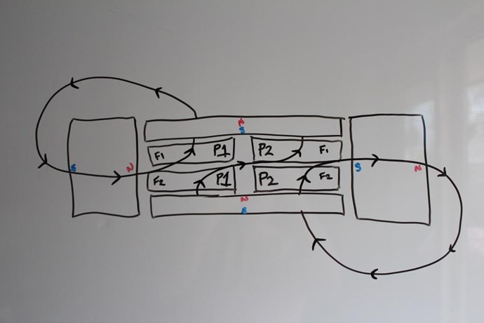
- Bias is supplied by the pair itself; each plate holds the other's working point.
- Modulate with a separate external high-temperature coil, transverse, at the chosen rate. The field should not reverse the plates; it should repeatedly move domain boundaries.
- Cool slowly with the modulation running. Rate matters: a fast quench freezes a disordered spread of states, which is the opposite of what is wanted.
- Ramp the modulation amplitude down smoothly, as in US2893107A. An abrupt cut leaves the system at a random phase of the cycle.
- Replace the spacers with the working coil former of the same thickness, without moving the plates.
Acceptance test for the process itself, before building anything: the treated pair should show a large, threshold-like change in flux for a small transverse field — measurable with a pickup coil and a signal generator. If the response is proportional and percent-level, the treatment did not produce what §2.1 requires, and no amount of coil winding will fix it.
6. How this maps onto Partnered Output Coils
Nothing above conflicts with the POC picture; it constrains what the magnetic element has to be for that picture to work.
- POC needs a magnetic system that can be pushed over a threshold and then switch, so the coils can lock into their blocking-oscillator behaviour rather than merely transformer-couple. §3.1 says a field-cooled ferrite pair can be prepared into exactly that state; §4.5 says such elements are manufactured commercially.
- The orthogonal drive has two independent justifications, and both survive the arithmetic: it keeps the output current out of the trigger circuit, and it acts along the soft direction for tipping the magnetisation. The 1986 measurement of hundreds of kilohms apparent drive impedance is the valve pushing back through that same path.
- The power factor requirement in §2.3 is a design rule for POC builds: the switch decides at the flux extremes, and if the load current has not gone to zero by then, the coil field opposes the switch. Near unity power factor the two are compatible; at 45° of phase the coil field would hold the valve shut. This predicts that a POC build will behave very differently with a resistive load than with a reactive one — which is cheap to test.
- Load dependence — the reports that the device needs a standing load of at least ~25 W and runs better under more load — is consistent with the same picture: with no sink, the switching energy has nowhere to go and reflects back into the magnetic system.
- The mains-synchronisation question raised in the thread has a number attached: a domestic 50/60 Hz stray field is of order five times the calculated trigger field, so a 60 Hz build should be captured by the mains, and a 400 Hz build should not. That is a concrete, checkable difference between the two versions, and it may explain why the 60 Hz builds were the fussy ones.
7. Falsifiable predictions
If conditioning stores a state (and not a clock), then:
- Heating a running device by ~10 K leaves the frequency where it is but changes amplitude and starting behaviour. If the frequency halves, the material is the clock and §3.2 is wrong.
- A treated pair shows threshold-like, not proportional, flux response to a small transverse field.
- Swapping one plate of a treated pair for an untreated one destroys the effect.
- Changing the gap after treatment degrades it, because the working point moves.
- Rotating the assembly relative to the Earth's field changes behaviour far more than the daily variation of that field does — the DC field is part of the bias, not a disturbance.
- Two pairs treated at different rates differ in their response band, not in a single sharp line.
- Heating above the stabilisation range erases the difference between treated and untreated plates.
8. What does not add up — stated openly
- No successful replication of the conditioning process appears in any thread or paper I could find. The process description descends from recollections, not from a published procedure.
- Barium ferrite is magnetically hard by design; its walls are meant to be difficult to move. The field-cooling literature is strongest for ferroelectrics, multiferroics, amorphous ribbons and thin films — not for large sintered hexaferrite plates. The analogues in §4 establish the class of process, not this application of it.
- If the 1986 output coil is read literally as 12 turns on a 1.5″ form, the flux swing implied by 24.2 V at 400 Hz is many times the static flux of the plates. Either the coil enclosed a much larger area than the form diameter suggests, or the swing genuinely exceeds the magnets' own flux. This is the single most uncomfortable number in the whole reconstruction and it is not resolved.
- The 1 kW and 5 kW claims do not sit comfortably with the stated wire gauges; the copper loss alone would exceed the stated thermal behaviour.
- Reported cold running and weight change are not addressed here at all. They are not needed for the conditioning argument, and mixing them in would only make the testable part harder to test.
9. Sources
Sweet material
Barium ferrite properties
Field cooling and poling
Bistable and magnetostrictive elements
Coupled cooling
Stabilisation practice
Markup from the orriginal:
# Magnet Conditioning in the Sweet VTA — what a thermal-magnetic process can and cannot store, and where the same process already exists in industry

Prepared for the *Floyd Sweet VTA — Partnered Output Coils* thread on aboveunity.com.

## 0. Scope, and why this is worth reading even if you think conditioning is a myth

The thread has two positions on conditioning. One says the orthogonal coils will not produce
output unless the magnet has been conditioned. The other says conditioning is a distraction that
Bearden attached to the device afterwards, and that the machine is explained by asymmetrical
induction and by the way the output coils are wound and loaded.

This document does not try to settle that by argument. It does three things instead:

1. It states what the **numbers** demand of the device, from the two documented versions.
2. It separates what a heat-and-field process **can** store in a hard ferrite from what it
   **cannot**, with the arithmetic shown, so the claim becomes testable instead of a matter of
   belief.
3. It lists **existing industrial and laboratory processes** with exactly the same structure
   — heat, apply a field, cool under that field, lock a state — with references. None of them
   are free-energy sources. They are ordinary materials engineering, used in production today.

The conclusion is in the middle of the two camps, and it is falsifiable: a thermal-magnetic
process can lock a **threshold, a symmetry, a switching depth and a response band**. It cannot
lock a clock at 60 Hz or 400 Hz. If that is right, conditioning is real but it is not what most
of the retellings say it is, and the frequency belongs to the loop — magnets, coils, load — which
is the position the engineering side of this thread already argues from.

Nothing below asserts where the energy comes from. That question is deliberately left open; the
material here stands or falls on measurements either way.

## 1. Two versions of the device. Do not mix their numbers

Almost every contradiction in the Sweet literature comes from mixing these two.

| | **1986, transcribed lab notes** | **1991, Sweet–Bearden report** |
|---|---|---|
| Plates | 1″ × 4″ × 6″ ceramic | 4″ × 6″ × ½″ in most retellings |
| Field between plates | "500+ gauss" | — |
| Output coil | **12 turns of #12 on a 1.5″ form** | not published; ≤300 turns is the only figure compatible with the stated mass |
| Drive coil | 250 turns of #18, orthogonal | orthogonal |
| Input | 7 V × 143 µA ≈ **1 mW** | 330 µW quoted in retellings |
| Output | **24.2 V × 4.6 A ≈ 111 W** | >1 kW claimed |
| Frequency | ~400 Hz | 60 Hz (also built for 50 and 400) |
| Capacitor | explicitly **"not a capacitor, no resonant effects"** | not stated |
| Thermal | ran 10 hours **without heating** | ran cold; frost on shorting |
| Mass | — | 6 lb, **weight reduced by 90 %** at 1 kW |

Two details from the 1986 notes deserve attention because they are measurements, not recollections:

- The drive coil's **apparent impedance in the assembled machine was hundreds of kilohms**,
  against 2–3 Ω on the bench. That is not a property of the coil; it is the valve pushing back
  into the trigger. At 143 µA this corresponds to roughly 7 V of induced back-voltage on the
  drive winding, i.e. the magnetic state is swinging on its own and the drive is only timing it.
- Sweet notes that the **magnet size is secondary to the coil volume**. That is a strong hint the
  plates set the bias and the coil volume sets the throughput.

Source for the notes: transcribed lab notes, hyiq.org (link in §9).

## 2. What the numbers demand

Three constraints fall straight out of the documented figures, and any model — conditioning or
no conditioning — has to satisfy them.

**2.1 The flux swing must be comparable to the whole magnet flux, not a few domain walls.**

For 120 V at 60 Hz the required flux amplitude is Φ = U√2 / (2πf N). With a few hundred turns
over the plate area this lands at **0.04–0.10 T of swing**, against a static field between the
plates of the same order (measured over the plate area, not on the axis: about 30 mT for ½″
plates, about 52 mT for 1″ plates; on the centre line alone you get 41–72 mT, which is why axis-only
estimates flatter the design). Same conclusion from the 1986 numbers by a different route: 111 W
at 400 Hz through 12 turns requires a swing at least as large as the magnets' own flux.

So: whatever modulates the flux has to move **most of it**. Reversible domain-wall wiggle in a
hard ferrite gives percent-level changes. That is two to three orders of magnitude short. Any
mechanism proposed here has to be a **switch**, not a nudge.

**2.2 The drive cannot be the source.**

250 turns at 143 µA produce, in a 76 mm gap, a field of order **0.5 µT** — about 0.001 % of the
working field, and a per-cycle energy about a million times below the output. Whatever the drive
does, it **triggers**; it does not deliver. This is the one point on which every position in the
thread already agrees, and it is worth stating numerically because it constrains everything else:
a trigger that weak can only work on a system sitting on a threshold.

**2.3 The output coil's own impedance decides whether a capacitor is needed.**

For the 1986 coil — 12 turns, 1.5″ form — the inductive reactance at 400 Hz is negligible, the
power factor is essentially unity, and Sweet's "no capacitor, no resonant effects" is consistent.
For a several-hundred-turn coil at 60 Hz the reactance is tens of ohms, the phase angle becomes
large, and the machine **would** need compensation. This resolves an apparent contradiction in the
literature: both "no capacitor" and "needs a tank" are true, for different builds.

It also matters for the switching argument in §3: with a large phase angle, the load current is
still flowing at the moment the flux reaches its extremes, and the coil field then opposes the
switch. Near unity power factor, the load current is zero exactly when the flux turns over.

## 3. What a heat-and-field process can and cannot lock into a hard ferrite

**3.1 What it can lock.** Cooling a ferrite through a temperature range while a field is applied
changes, permanently, the state the domain structure settles into:

- a **stabilised wall position** — ionic and vacancy rearrangement around a domain wall digs the
  wall its own potential well (this is the same physics as disaccommodation / magnetic after-effect,
  a standard and unwanted property of soft ferrites, exploited deliberately here);
- an **induced uniaxial anisotropy** — magnetic annealing, used in production to square hysteresis
  loops;
- a **bias point held by the partner magnet**, if the pair is cooled together in the final geometry;
- a **bistable configuration** — a state which, once pushed past a threshold, flips as a whole
  rather than proportionally.

The last item is the important one, because §2.1 demands a switch. And bistability of exactly this
kind is manufactured on an industrial scale — see §4.5.

**3.2 What it cannot lock: a clock.**

The popular version of the story says a frequency is written into the magnet. Run the arithmetic.

Thermally activated relaxation gives a response time τ = τ₀·exp(E/kT). Take the standard attempt
time τ₀ ≈ 10⁻¹² s. Then at room temperature:

| Frequency | Implied barrier |
|---|---|
| 12 Hz | 0.60 eV |
| 60 Hz | 0.56 eV |
| 400 Hz | 0.51 eV |

Two observations, and they cut in opposite directions.

*In favour of conditioning the whole span from the reported 12 Hz treatment rate to the 400 Hz
running frequency fits inside **0.09 eV**, a single family of ionic hops in an oxide. The **width**
of that band is independent of the assumed attempt time — it cancels. So the claim "the treatment
prepares a population of centres whose response lies in this band" survives the arithmetic.

*Against the strong version the absolute barrier does **not** cancel — change τ₀ by three orders
of magnitude and every number in the table moves by ±0.06 eV. Worse, the same activation law makes
the response frequency **double for roughly every 10 K**. A machine that ran about 11 K below room
temperature would have drifted from 60 Hz to about 27 Hz if the material were the clock. It did not.

**Conclusion* cooling writes a **threshold, a symmetry, a switching depth and a response band**.
The specific number inside that band is set by the loop — the pair, the coils, the load, and any
external synchronising field. That is a different claim from "the magnet remembers 60 Hz", and it
is compatible with the position that the frequency comes from the circuit.

**3.3 A consequence worth checking on the bench.** If the material sets a band and the loop picks
the number, then **heating a running device by ~10 K should not move the output frequency**, but
should change the amplitude and the ease of starting. If the material were the clock, the frequency
would halve. That is a one-afternoon experiment with a hot-air gun and a thermocouple, and it
separates the two camps in this thread cleanly.

## 4. The same process, already in industry and in the literature

None of these are anomalous-energy claims. They are ordinary processes with the structure
*heat → apply field → cool under field → state is locked*. They establish that the class of process
Sweet is said to have used is real, common, and in some cases sold by the million.

**4.1 AC poling during field cooling (ferroelectric single crystals).** PIMN-PT cooled from 100 °C
to 70 °C under an alternating electric field of about 4 kV/cm at low frequency. The domain and phase
structure after treatment differs from ordinary DC poling, and the piezoelectric response is higher.
The authors call it field-cooling alternating-current poling (FC ACP). This is the closest published
analogue to "alternating field applied while cooling". Zhang et al., "High piezoelectricity after
field cooling AC poling in temperature stable ternary single crystals manufactured by
continuous-feeding Bridgman method", *Journal of Advanced Ceramics*, 2022 — PIMN-0.30PT,
4 kV(rms)/cm applied from 100 °C down to 70 °C, d₃₃ = 2750 pC/N afterwards.

**4.2 Patent precedent for the same recipe, 1959.** US2893107A, barium titanate: an alternating
voltage of fixed frequency and amplitude is applied during gradual cooling, and the amplitude is then
ramped smoothly to zero. The patent explicitly claims frequency and duration of treatment as process
variables. If someone tells you "applying a chosen frequency while cooling and then ramping it down"
is an invented procedure, this patent is 67 years old.

**4.3 Thermal poling of glass.** Heat, apply a strong DC field, cool with the field on. Mobile ions
redistribute and a frozen-in internal electric field remains afterwards. Confirms the general
principle: heat raises mobility, field shapes a non-equilibrium structure, cooling freezes it.

**4.4 Magnetic annealing and induced anisotropy in ferrites.** Standard production practice for
square-loop and low-loss ferrites: annealing in a magnetic field produces a uniaxial anisotropy
aligned with the applied field, through the ordering of cation vacancies and Fe²⁺ ions. The same
ionic mechanism produces disaccommodation — the well-known decay of permeability after
demagnetisation — which is direct evidence that domain walls in ferrites do get pinned by a
thermally activated, freezable ionic environment.

**4.5 Wiegand wire — bistability manufactured on purpose. The closest existence proof.**
A Vicalloy wire (Fe₀.₄Co₀.₅V₀.₁) is processed by cyclic torsional and longitudinal strain plus
annealing, so that the surface layer ends up magnetically soft while the core stays hard. A weak
external field then flips the core as a single large Barkhausen jump, generating a voltage pulse in
a pickup coil whose amplitude is **independent of the rate of change of the applied field** — the
pulse is the same whether the field is swept fast or slowly. These are manufactured and sold as
self-powered, battery-free sensors and multi-turn rotation counters; no battery, no external supply
to the sensing element.

This is the industrial existence proof for the exact combination §2.1 and §2.2 demand: *a processed
magnetic element in which a weak trigger produces a full flux reversal, because the processing put
it into a threshold state.* Note what it does and does not prove. It proves that "processing writes
a switching threshold, and a tiny input then releases a large flux change" is ordinary, commercial
materials engineering — not a story. It does not prove anything about energy balance: a Wiegand
pulse is microjoules, and the energy comes from the applied field doing work on the core. The
transferable part is the **mechanism of the valve**, not a power claim.

Original patent: J. R. Wiegand, "Bistable Magnetic Device", US3820090 (1974) — a wire with a soft
core and a hard shell produced by twisting it back and forth about its axis, the shell holding the
core until an external field flips it, the reversal detected as a pulse in a pickup coil. Modern
review and measured pulse characteristics in the sources list.

**4.6 Acousto-magnetic EAS tags.** An amorphous magnetostrictive ribbon plus a separate bias magnet;
a weak AC field excites a mechanical resonance and the magnetostrictive coupling returns a magnetic
signal to a pickup coil. Heat treatment in a field — in US6011475A, a field of at least ~1000 Oe
applied at an angle to the ribbon plane — sets the induced anisotropy, the domain width, the signal
amplitude and the stability of the resonance. Same structural claim again: the anneal decides what
the finished element does. Two relevant lessons: a weak field really can drive a
processed magnetic element to produce a substantial pickup signal; and the frequency there is set by
the ribbon's geometry, not by the treatment frequency — a caution against the "written frequency"
reading.

**4.7 AC annealing of magnetic wire — the decisive counter-example on frequency.** Amorphous CoFeBSi
wire was annealed by AC current at 50 Hz and at 100 kHz under various applied fields. The treatment
frequency measurably changed the domain structure and the giant magnetoimpedance. But the frequency
of maximum response afterwards was about 4.5 MHz — **not** the annealing frequency. Treatment
frequency influences the resulting structure; it does not become the resonance of the product.
*Journal of Alloys and Compounds*, 2016.

**4.8 Field cooling of coupled magnetic layers (exchange bias, MRAM).** Two or more magnetic layers
are heated and cooled together under a field; their relative orientation is locked during cooling.
Production technology in magnetic memory. The transferable principle is the one the Sweet accounts
insist on: **the final state of each magnetic part depends on the other part, during cooling.**
Patent US7160738B2; *Phys. Rev. Lett.* 76, 4624; *Nat. Commun.* 11648.

**4.9 Magnetoelectric field cooling (Cr₂O₃, TbMnO₃).** Cooling under simultaneous electric and
magnetic fields selects the antiferromagnetic domain state, which then persists. The closest magnetic
analogue to "an electric field plus cooling sets a retained magnetic state" — with the honest caveat
that these are dedicated magnetoelectrics and a sintered barium ferrite is not one.

**4.10 Industrial stabilisation of magnets in the final assembly.** Engineering practice is to
stabilise magnets **in the magnetic circuit in which they will operate** — magnetise the assembly,
thermally cycle it, and if necessary knock it down with a partial AC demagnetising field. NASA and
industry guides both say this. It directly supports the one procedural claim the Sweet accounts make
that nobody disputes: if the working point matters, treat the **pair**, at the working gap.

## 5. A concrete procedure, if anyone wants to test the claim

Stated as an experiment, not as a recovered recipe. Sweet's actual parameters are not published.

1. **Select** two plates by mapping the surface field, not by peak strength. What matters is a flat
   map: the reported "one magnet in thirty" reads naturally as a uniformity selection, and §3 gives
   the reason — a spread of local barriers gives a spread of switching times, and the flip smears out
   instead of happening as one jump.
2. **Assemble** the pair at the final working gap, attracting orientation, fixed with heat-resistant
   non-magnetic spacers. Working coils stay out of the hot zone.
3. **Heat** the pair as one magnetic system. Moderate (100–200 °C) changes defect mobility and
   stresses; approaching the Curie point of barium ferrite (~450 °C) restructures far more but risks
   losing magnetisation and cracking the plates. Ramp slowly — ferrite is brittle and a large plate
   will crack on thermal shock.
4. **Bias** is supplied by the pair itself; each plate holds the other's working point.
5. **Modulate** with a separate external high-temperature coil, transverse, at the chosen rate. The
   field should not reverse the plates; it should repeatedly move domain boundaries.
6. **Cool slowly with the modulation running.** Rate matters: a fast quench freezes a disordered
   spread of states, which is the opposite of what is wanted.
7. **Ramp the modulation amplitude down smoothly**, as in US2893107A. An abrupt cut leaves the system
   at a random phase of the cycle.
8. **Replace** the spacers with the working coil former of the same thickness, without moving the
   plates.

Acceptance test for the process itself, before building anything: the treated pair should show a
**large, threshold-like** change in flux for a small transverse field — measurable with a pickup coil
and a signal generator. If the response is proportional and percent-level, the treatment did not
produce what §2.1 requires, and no amount of coil winding will fix it.

## 6. How this maps onto Partnered Output Coils

Nothing above conflicts with the POC picture; it constrains what the magnetic element has to be for
that picture to work.

- POC needs a **magnetic system that can be pushed over a threshold and then switch**, so the coils
  can lock into their blocking-oscillator behaviour rather than merely transformer-couple. §3.1 says a
  field-cooled ferrite pair can be prepared into exactly that state; §4.5 says such elements are
  manufactured commercially.
- The **orthogonal drive** has two independent justifications, and both survive the arithmetic: it
  keeps the output current out of the trigger circuit, and it acts along the soft direction for
  tipping the magnetisation. The 1986 measurement of hundreds of kilohms apparent drive impedance is
  the valve pushing back through that same path.
- The **power factor requirement** in §2.3 is a design rule for POC builds: the switch decides at the
  flux extremes, and if the load current has not gone to zero by then, the coil field opposes the
  switch. Near unity power factor the two are compatible; at 45° of phase the coil field would hold
  the valve shut. This predicts that a POC build will behave very differently with a resistive load
  than with a reactive one — which is cheap to test.
- **Load dependence** — the reports that the device needs a standing load of at least ~25 W and runs
  better under more load — is consistent with the same picture: with no sink, the switching energy has
  nowhere to go and reflects back into the magnetic system.
- The **mains-synchronisation** question raised in the thread has a number attached: a domestic 50/60 Hz
  stray field is of order five times the calculated trigger field, so a 60 Hz build **should** be
  captured by the mains, and a 400 Hz build should not. That is a concrete, checkable difference
  between the two versions, and it may explain why the 60 Hz builds were the fussy ones.

## 7. Falsifiable predictions

If conditioning stores a state (and not a clock), then:

1. Heating a running device by ~10 K leaves the frequency where it is but changes amplitude and
   starting behaviour. If the frequency halves, the material is the clock and §3.2 is wrong.
2. A treated pair shows threshold-like, not proportional, flux response to a small transverse field.
3. Swapping one plate of a treated pair for an untreated one destroys the effect.
4. Changing the gap after treatment degrades it, because the working point moves.
5. Rotating the assembly relative to the Earth's field changes behaviour far more than the daily
   variation of that field does — the DC field is part of the bias, not a disturbance.
6. Two pairs treated at different rates differ in their **response band**, not in a single sharp line.
7. Heating above the stabilisation range erases the difference between treated and untreated plates.

## 8. What does not add up — stated openly

- No successful replication of the conditioning process appears in any thread or paper I could find.
  The process description descends from recollections, not from a published procedure.
- Barium ferrite is magnetically hard by design; its walls are meant to be difficult to move. The
  field-cooling literature is strongest for ferroelectrics, multiferroics, amorphous ribbons and thin
  films — not for large sintered hexaferrite plates. The analogues in §4 establish the class of
  process, not this application of it.
- If the 1986 output coil is read literally as 12 turns on a 1.5″ form, the flux swing implied by
  24.2 V at 400 Hz is many times the static flux of the plates. Either the coil enclosed a much larger
  area than the form diameter suggests, or the swing genuinely exceeds the magnets' own flux. This is
  the single most uncomfortable number in the whole reconstruction and it is not resolved.
- The 1 kW and 5 kW claims do not sit comfortably with the stated wire gauges; the copper loss alone
  would exceed the stated thermal behaviour.
- Reported cold running and weight change are not addressed here at all. They are not needed for the
  conditioning argument, and mixing them in would only make the testable part harder to test.

## 9. Sources

Sweet material
- Transcribed lab notes — https://www.hyiq.org/Downloads/Lab%20Notes%20Transcribed%20-%20Floyd%20Sweet.pdf
- Collected VTA documents and Bearden recollections — https://www.rexresearch.com/sweet/1nothing.htm
- Later construction description — https://www.novakcorp.com/energy/experiments/svta.htm

Barium ferrite properties
- Natural resonance of BaFe₁₂O₁₉ — https://pubs.rsc.org/en/content/articlehtml/2017/dt/c7dt01708a
- High-frequency properties of hexaferrites — https://pmc.ncbi.nlm.nih.gov/articles/PMC6955991/
- Magnetic viscosity and activation volume in BaFe₁₂O₁₉ — https://onlinelibrary.wiley.com/doi/full/10.1002/pssb.202300425
- Low-temperature relaxation in Ba hexaferrite — https://journals.aps.org/prb/abstract/10.1103/PhysRevB.53.3336

Field cooling and poling
- Field-cooling AC poling of a ferroelectric crystal — https://www.sciopen.com/article/10.1007/s40145-021-0490-1
- US2893107A, barium titanate, AC field during cooling — https://patents.google.com/patent/US2893107A/en
- High-temperature AC poling review — https://doi.org/10.1039/D2MA00559J
- Thermal poling of glass — https://www.sciencedirect.com/science/article/pii/0030401894902607

Bistable and magnetostrictive elements
- J. R. Wiegand, "Bistable Magnetic Device", US3820090 (1974) — https://patents.google.com/patent/US3820090A/en
- Review of the self-powered Wiegand sensor and its applications — https://www.mdpi.com/2312-7481/8/10/128
- Output characteristics and circuit modelling of a Wiegand sensor — https://www.mdpi.com/1424-8220/19/13/2991
- Annealing of amorphous ribbons for EAS markers, US6011475A — https://patents.google.com/patent/US6011475A/en
- Amorphous alloys for magneto-acoustic markers, US6645314B1 — https://patents.google.com/patent/US6645314B1/en
- AC-current annealing of magnetic wire — https://doi.org/10.1016/j.jallcom.2015.11.125

Coupled cooling
- Magnetic annealing of coupled MRAM layers — https://patents.google.com/patent/US7160738B2/en
- Positive exchange bias after field cooling — https://journals.aps.org/prl/abstract/10.1103/PhysRevLett.76.4624
- Domain-pattern memory in coupled ferromagnets — https://www.nature.com/articles/ncomms11648
- Electric-field control of Cr₂O₃ domains — https://digitalcommons.unl.edu/physicsbinek/73/
- Electric field cooling of TbMnO₃ — https://www.nature.com/articles/s41535-020-00289-z

Stabilisation practice
- NASA/Princeton guide to permanent magnet stability — https://ntrs.nasa.gov/api/citations/19750014146/downloads/19750014146.pdf
- Ferromagnetic Core Design and Application Handbook — https://www.worldradiohistory.com/BOOKSHELF-ARH/Ferromagnetic-Core%20Design%20and%20Application%20Handbook.pdf
- Industrial magnet stabilisation and calibration — https://www.adamsmagnetic.com/resource/magnet-stabilization-and-calibration/








-sitting-on-top-of-the-vta---demo-2.jpg?width=690&upscale=false)