Hey Marcel,
I believe you're on the right track! I am still investigating some of this field.
I think the quote I gave is important to understand:
Antenna Theory and Electron Spin Resonance, or Electron Paramagnetic Resonance all come from Wave Mechanics and are a Result of Wave Mechanics, if you like Experiments proving that Wave Mechanics are correct and hold water!
The Antenna and EPR are the Effect of Wave Mechanic's, Schrödinger's Wave Equation:
At Resonance, we get Maximum Amplitude, as we all know, but we get the minimum Impedance also, most dont think about this part. This is where the Flow of Current has the least Impedance and can flow much more freely! This is what Floyd Sweet talked about:
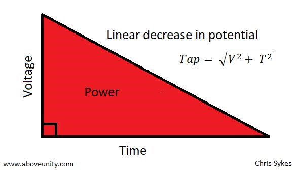
Resonance frequencies may be maintained quite constant at high power levels so long as the load remains constant. We are all familiar with AM and FM propagation, where in the case as AM, the voltage amplitude varies, and with FM, the frequency is modulated.
However, the output power sees a constant load impedance, that of the matched antenna system. If this changes, the input to the antenna is mismatched, and standing waves are generated resulting in a loss of power.
I believe the Frequency of the HV should be at the Fundamental Coils Frequency, so for example, if the POC are Resonant at 680KHz, then the HV Source should be 680KHz, this is my opinion.
The Sub-Harmonic can be any of the lower something like λ/50:
Kind time of day. Maybe here we will find a common language. At once I will say that I do not sit at forums much. No time ! However, now for the 5th time I am collecting Akulin for a capacity increase. There are ideas .... But in fact the people are looking for a bit of everything is not right. All these systems operate on the basis of standing and traveling waves. It is necessary first to catch the motion of particles in the coil. Those. as Kapanadze does with a tester or an ammeter. Only at HF frequencies no ammeter will help and you will need to catch an oscilloscope. The first rule: Wind the coil 40 meters. 2. Find out its resonant frequency (1/4 wave) Inductor 1/4 = 10 meters of the same wire (for example, 2.5mm) Connect the generator to a 10 meter coil, drive the rectangles at a frequency of 1 MHz and crawl higher until 40 meters do not appear sinusoid. The maximum amplitude. The generator is desirable to take a normal, laboratory! With output adjustment from 0 to 20 volts. We achieve maximum amplitude and move tenths of a kilohertz until it starts to dance. This is your wave resonance !!! We fix the frequency and voltage. It is for this all have to do the generators. Further ... Tesla we shake under this frequency that the effect has turned out. Then we do everything as I did or the Shark. In this case, everyone wants to repeat this device. Forward! We fix everything beautifully and stiffly, without forgetting that the resonance and effect can escape in the case of fastenings on the snot. We need to get the effect itself and work, and not a ready device. Once you begin to understand what to do next, you can already move. So .... Tesla, as we know, also wets the sinusoid. Suppose your frequency is 1.821MHz. The frequency, but alas. It is necessary to adjust Tesla on it. The shark used a critic between Tesla and the toroid (Antenna) over the inductor. This is just an accurate adjustment. It is needed before launching. Then the system holds and no matter what has slipped in not large limits. But! Again ... What where? On the Inductor we feed the signal of rectangles with a frequency of 1/50. Consider: 1820: 50 = 36.4 kHz pumping a rectangle through the junction (Pot) with 23-29 turns of wire 2.5 squares. I repeat, you need to make the voltage on this harmonic not 10-20 volts, but higher by an order of magnitude. Approximately up to 50-60 volts and get the same dancing effect at the output. Further ! Do not forget that Tesla does not need strong power. Do not let sparks run and wet so that it breaks through. This is not necessary !!! It's better to make a controlled Tesla. Continue: The output voltage will be 195-200 volts. This voltage will not be higher. Why? Later we will return to this. It is necessary to rewind the transformer-reactor (Coil) so as to obtain the desired voltage. This requires experiments. Remember that we push the current in the reactor with a transverse wave. Created by Tesla. In the coil another wave is formed under the action of pumping by rectangles. The particles of which constantly rotate left and right. By giving them the movement of the pulsating Tesla, we disperse them in the very conductor. This is a gemmoroid understanding, but a fact. Tesla must operate in one half-cycle or one arm of the transistor. It is advisable to manage the Tesla pack - pulse generator. When everything is clearly adjusted, you will see how the effect manifests when changing the width of the pack. Consumption Tesla is scanty, and pumping does not strain at all. The current at the output is up to 7 amperes and the voltage is 200-209 volts. Bulbs and PSU pulses work well. Now for removal: 1. The coil is connected via a diode bridge. No parallel capacitors !!! 2. You need from Tesla only one half wave. Otherwise Tesla will take what she gave, back !!! Therefore, and put the diode from the ground to the very take-off coil (40m) The shark did this at the reception. He removed one part of the sine at the reception itself. Because Tesla. No one knows this and -bip-tsya to this day, nichrome does not work. It's clear! You need to swing the swing in the coil of energy removal. It is there that we push the current. By the way, the surplus from Tesla and the frequency setting of the Shark used a simple light bulb. Since the Inductor is galvanically isolated from the entire circuit, the light bulb serves as a resistive load to suppress surplus from cords and pickups. You can not bet, but do not rock Tesla very much. Do not ! Remember that the current is subject to voltage. This I see from experiments that I spent 2 more years ago. Next: The diode on the receiving take-off coil destroys one half-cycle and so we swing the oscillations without hindering them by the negative Tesla period. This, too, many do not know and continue to sculpt. That's why Roman (Shark) says that he is eating ground ... Everything is right! Because it kills the half-period pulse at the reception, which is grounded. This can be seen in all his settings! I wondered for a long time why he decided to use this solution and realized that it's easier to pick up BB diodes. Since interference at such frequencies in Tesla will lead to its improper operation. In other words, it will not be possible to cut off the half-period. Kapa solved this issue with an arrester and rectifiers at low frequencies. There everything is simpler, but more wires .... So on the German installation the diode is small, Tesla is far away, the grounding cable is long. By the way is equal to the length of Tesla !!! Do not forget about grounding .... On this installation it is important and without good support (grounding) will not work. Do not forget that the systems use high voltage. As we know, it moves even in the air. That's why grounding is necessary. Plus wave resonance and safety .... Like that .....
Ref: Ruslan K
I know Floyd Sweet and Tariel Kapanadze both had Mains Frequency on the Output, I am guessing, this is just a sub-harmonic, by design, of the system.
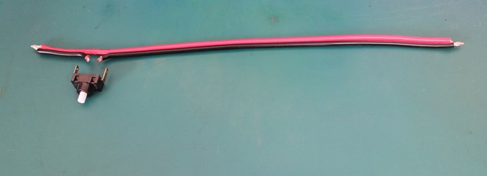
I believe the disconnected wire is just a wire spacing between the primary coil, to reduce Self Induction. Its a thing he did talk about in the Tesla stuff he talked about.
The truth is, the fundamental Method, it cant be all that different, from Floyd Sweet, to Tariel Kapanadze, to us trying to learn what those before us seemed to grasp more easily than we do today.
For example, the Output Coil, it is exposed to the exact same phenomena as the globe:
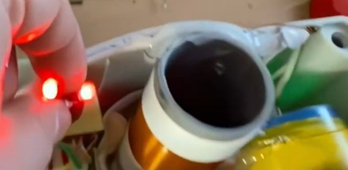
All the subatomic particles will be exposed to the same phenomena, High Voltage changes the state of the particles, you can check for your self:
To change electron states using High Voltage and Modulating Magnetic Fields, physicists rely on the fact that an electron’s energy level and spatial distribution (its "state") are determined by the electromagnetic environment it inhabits. Historically and in modern labs, this is achieved through two primary mechanisms: the Stark Effect (for electric fields) and the Zeeman Effect (for magnetic fields).
1. High Voltage and the Stark Effect
When a high-voltage electric field is applied to an atom, it physically pulls the electron in one direction and the nucleus in the other. This interaction changes the electron's potential energy.
- Process: An external electric field (\(E\)) is created by applying a high voltage across two plates. This field interacts with the electron’s position (\(r\)), adding a term to the Hamiltonian (the total energy equation): \[V_{Stark} = -eE \cdot r\]
- Result: This "stretches" the electron cloud. Energy levels that were once the same (degenerate) split apart.
- Historical Use: In the early 20th century, Johannes Stark used high-voltage discharge tubes to show that spectral lines of hydrogen would split, proving that electric fields directly modify the internal quantum states of atoms.
2. Modulating Magnetic Fields and the Zeeman Effect
Electrons have a property called magnetic moment, which comes from their spin and their orbital motion around the nucleus. Like a tiny compass needle, an electron wants to align with an external magnetic field.
- Process: When a magnetic field (\(B\)) is applied, the electron's energy depends on its orientation relative to that field. The energy shift is given by: \[\Delta E = -\mu \cdot B\] where \(\mu\) is the magnetic moment.
- Modulation: By "modulating" the field (changing its strength or frequency), researchers can drive electrons between these split states. This is the basis of Electron Paramagnetic Resonance (EPR).
- Result: The field "lifts the degeneracy," meaning electrons with different spins (up vs. down) no longer have the same energy.
3. Combined Process: State Manipulation
In practice, these two forces are often used together to achieve precise control:
Component Function Effect on Electron High Voltage (Static) Defines the potential "landscape." Shifts and splits orbital energy levels (Stark). Magnetic Field (Static) Defines the spin orientation. Splits states based on magnetic alignment (Zeeman). Modulation (Dynamic) Provides a "kick" at a specific frequency. Induces transitions (jumps) between the newly created states.
The "How-To" Summary:
- Preparation: Place the sample in a high-voltage environment to define the orbital states.
- Splitting: Apply a strong magnetic field to separate the spin states.
- Resonance: Modulate a secondary magnetic field (often at radio or microwave frequencies). When the modulation frequency matches the energy gap between states, the electron "flips" its state.
The fact of the matter is, Floyd Sweet Wrote about these processes, he was vague and did not go into any detail, but I believe it was a well known phenomena in closed circles, back in the 40's 50's and 60's.
Hey, if I am wrong, then I am happy to say, but, thing is, we do have evidence for this arrangement, it has merit and aligns with Floyds Writings. I have been a bit lazy in the last year or so, and slowed down in my experiments, so some of this is not yet fully investigated. I will get there, in time.
Chris