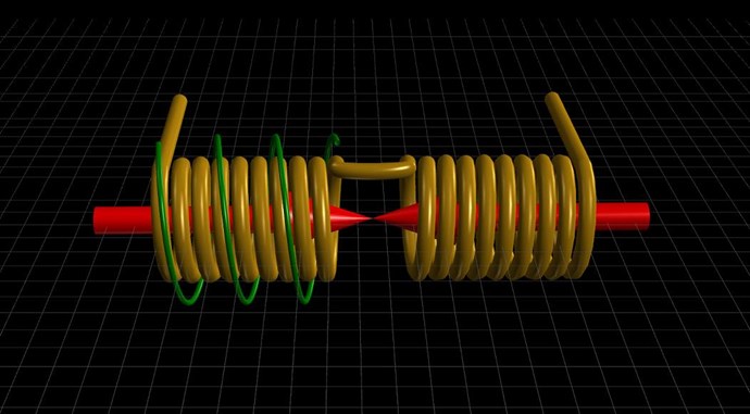
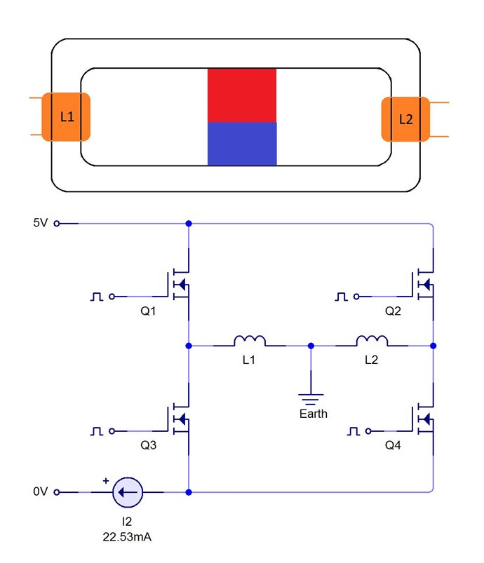
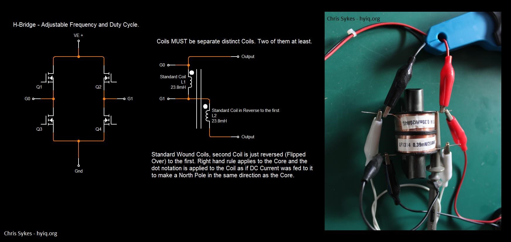
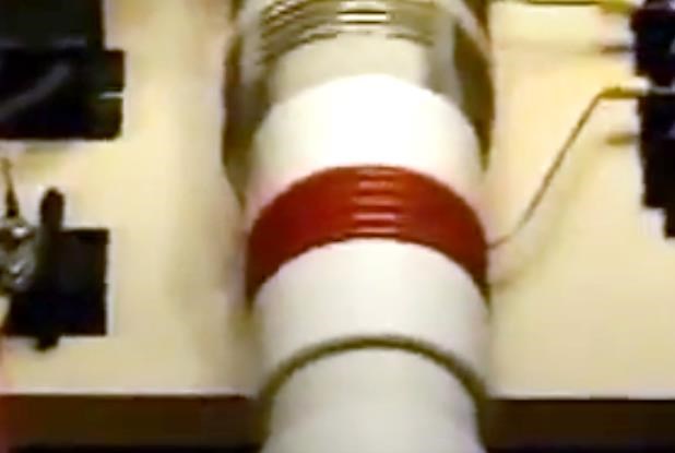
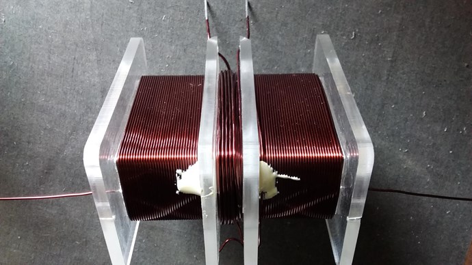
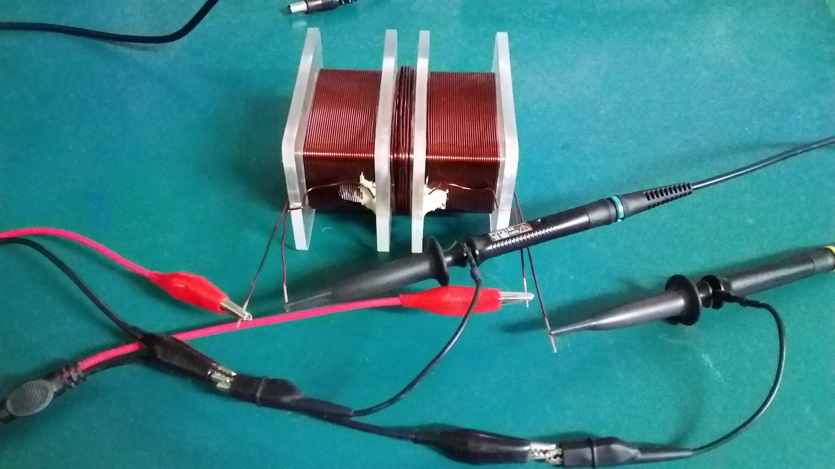
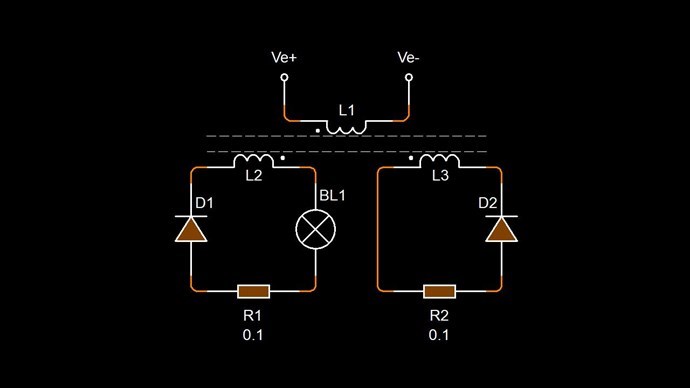
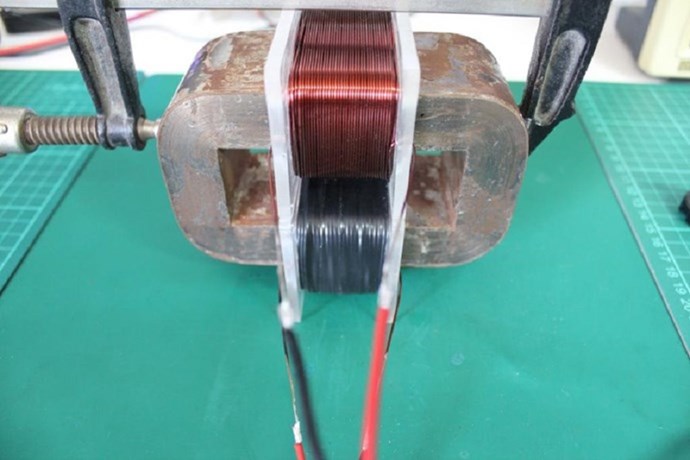
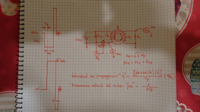
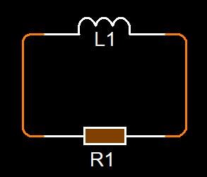
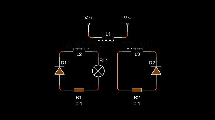
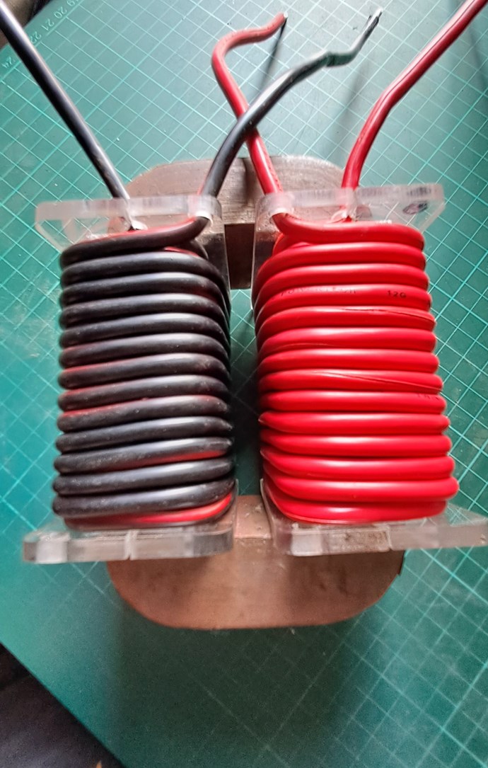
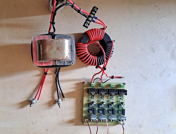
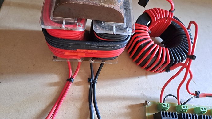
Many times I have talked about Partnered Output Coils. People call them Bucking Coils. I prefer not to use this terminology. Its a bit confusing. I use a Sudo Diagram:
I have been through the "Common Mode Choke" and why Partnered Output Coils are different in the Timing Thread.
People in general seem to have a largely misunderstood inception of Partnered Output Coils, or Bucking Coils in general.
Andrey Melnichenko also shows a Bucking Component to his Coils. But the Coils were not Bucking as we think of Bucking.
Here is an example of how it is a misunderstood area of Science. Itsu is an excellent Experimenter, this is not intended as a dig, just an observation:
Studding this video, it is obvious there has been a lot of effort gone into this. A lot of work! But Itsu is missing something, something that is the most important of all! Can you spot what it is?
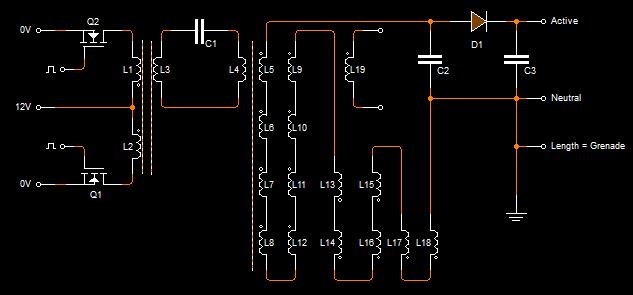
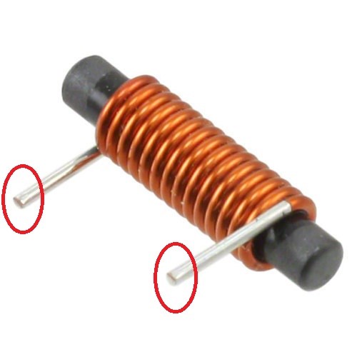
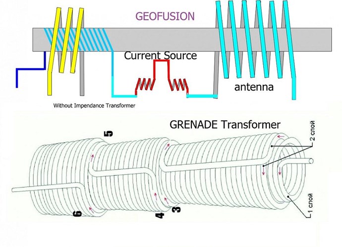
His Grenade Coil is wrong! This also pointed out in the comments.
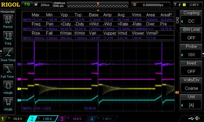
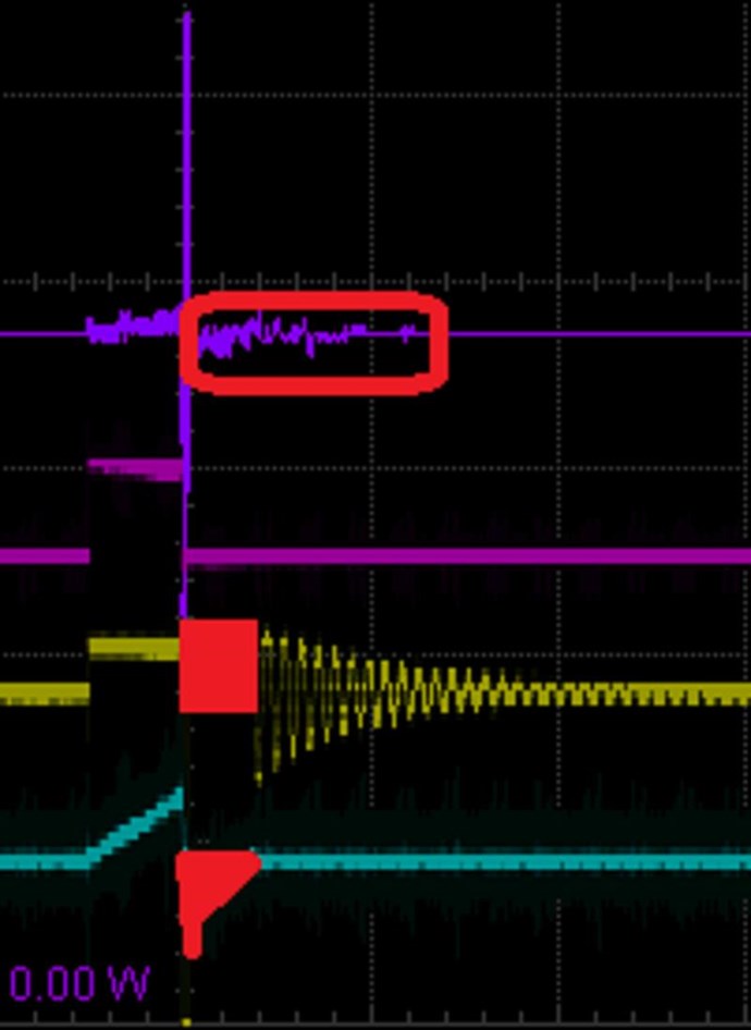
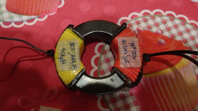
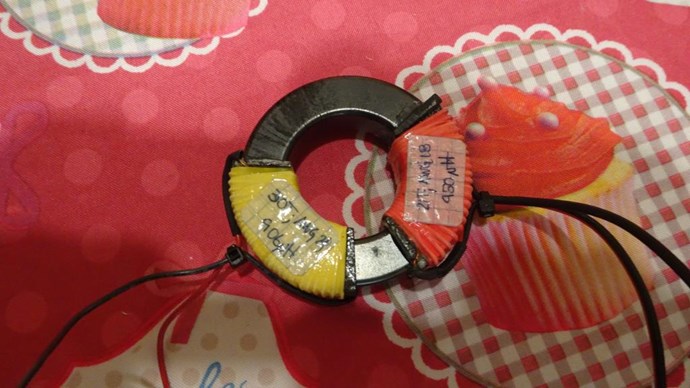
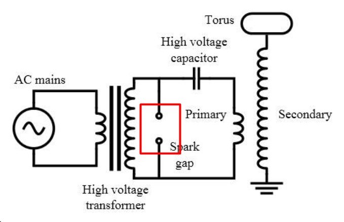
The Grenade Coil must have, what would normally be thought of as a "Non-Inductive" Component, a Bucking Component! Actually, we will find, as time goes on, this is Highly, extremely Inductive!
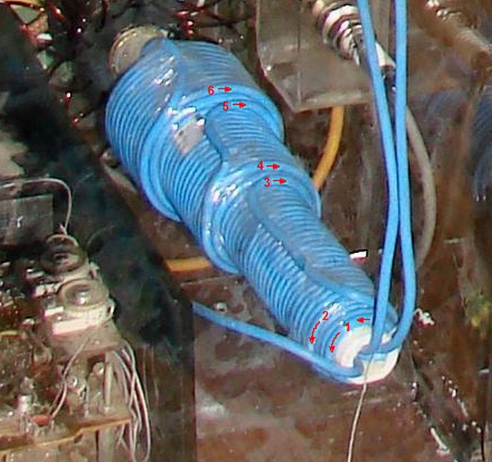
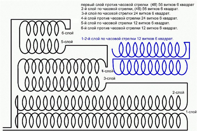
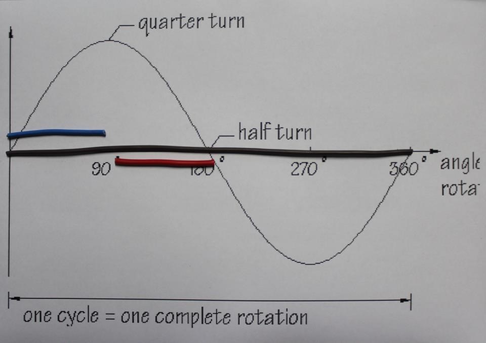
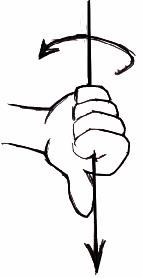
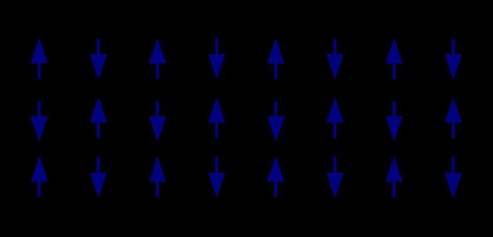
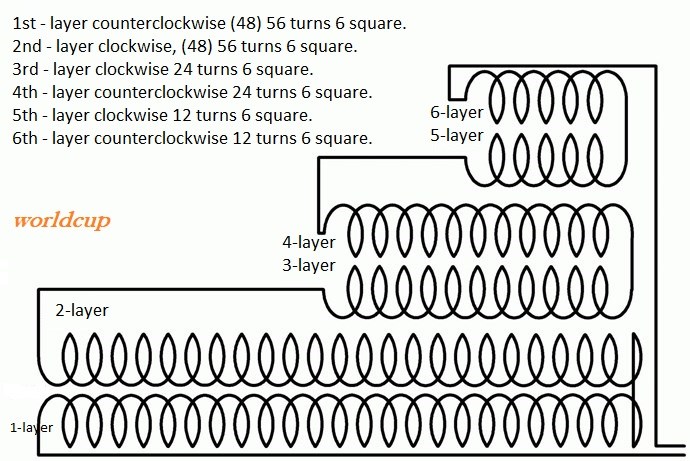
Turns 1 and 2 are Counter Clockwise, turns 3, 4, 5 and 6 are Clockwise.
Ask yourself the question, how is it that a huge amount of Electrical Power can be extracted from a NON-Inductive Coil?
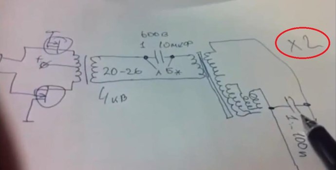
Also from Ruslan Kulabuhov
It is actually this Extremely Inductive Component that makes a Common-Mode Choke work as it does!
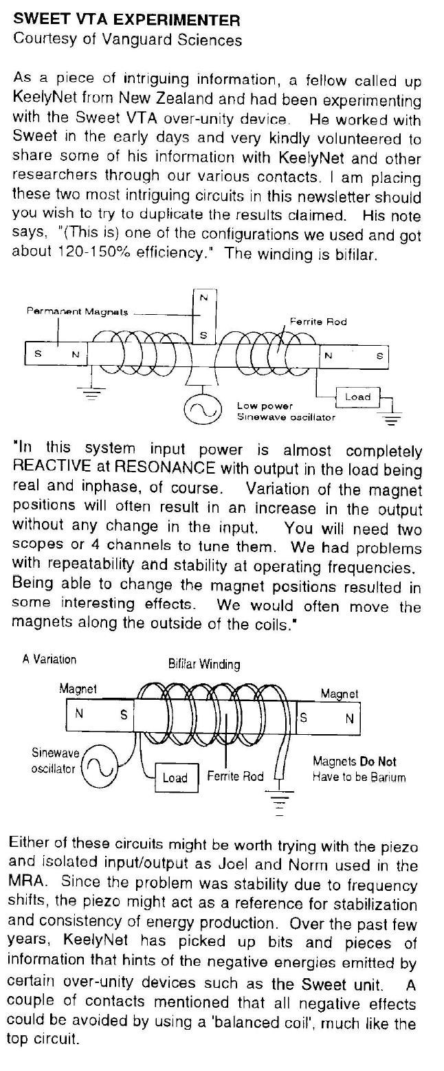
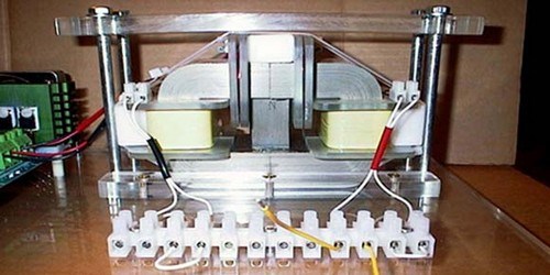
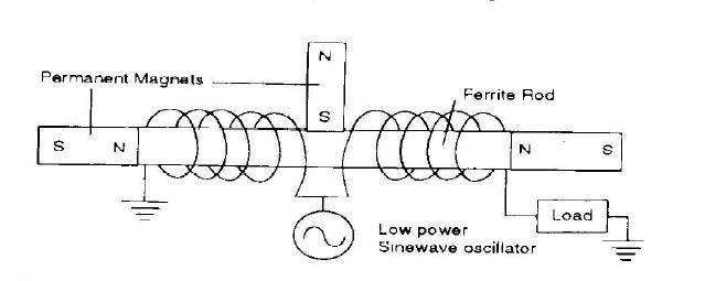
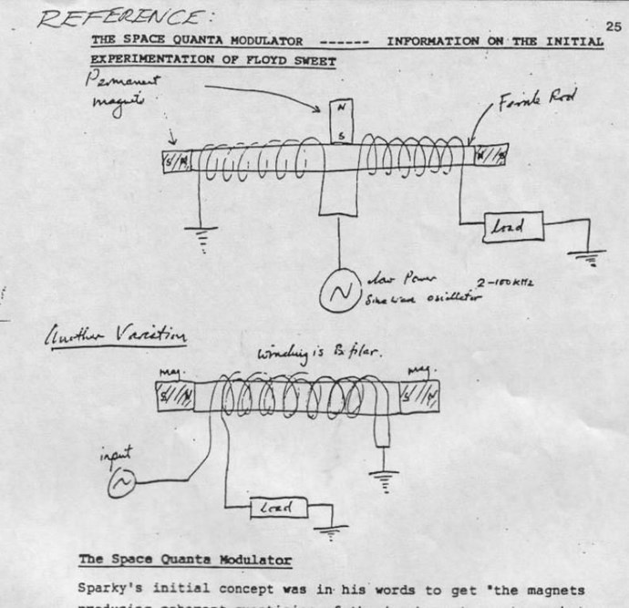
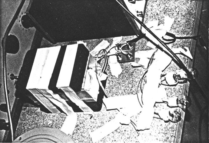
Floyd Sweet also shows this exact same Bucking of Magnetic Fields:
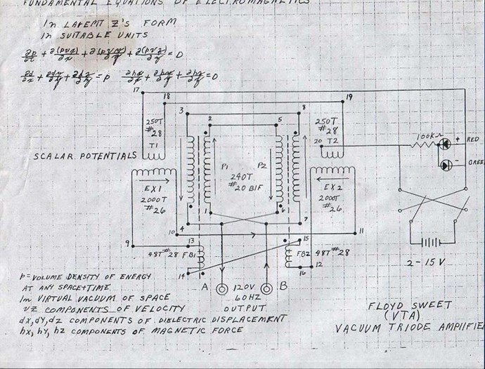
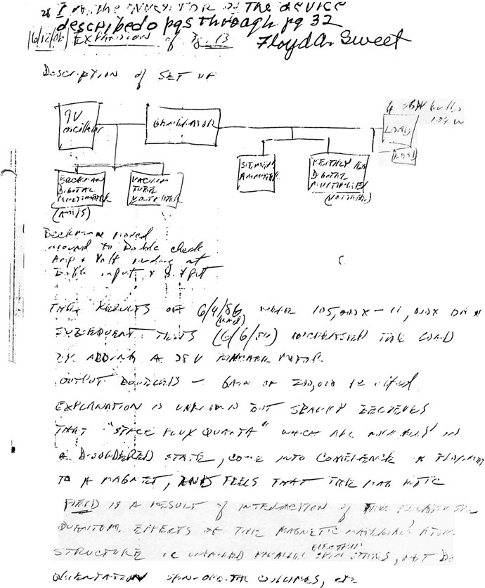
The VTA Description is as follows:
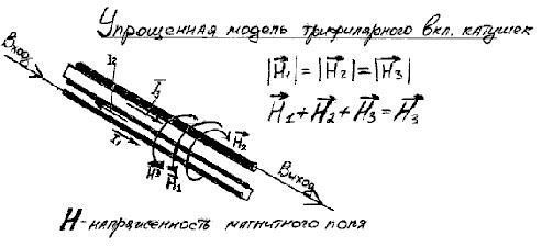
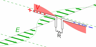
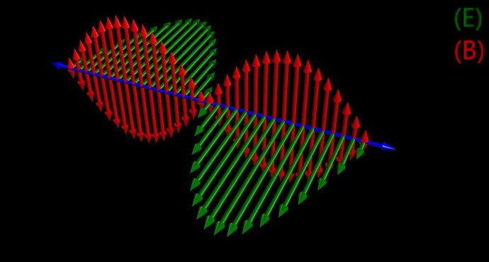
Consider for a moment the construction of the triode which includes the bifilar coils located within the fields of the two magnets.
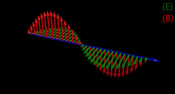
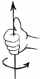
When the current in one half of the conductors in the coils (i.e., one of the bifilar elements in each coil) of the device is moving up, both the current and the magnetic field follow the right-hand rule.
The resultant motional E-field would be vertical to both and inwardly directed.
At the same time the current in the other half of the conductors in the coils is moving down and both the current and magnetic field follow the right-hand rule.
The resulting motional E-field is again vertical to both and inwardly directed.Thus, the resultant field intensity is double the intensity attributable to either one of the set of coil conductors taken singularly.
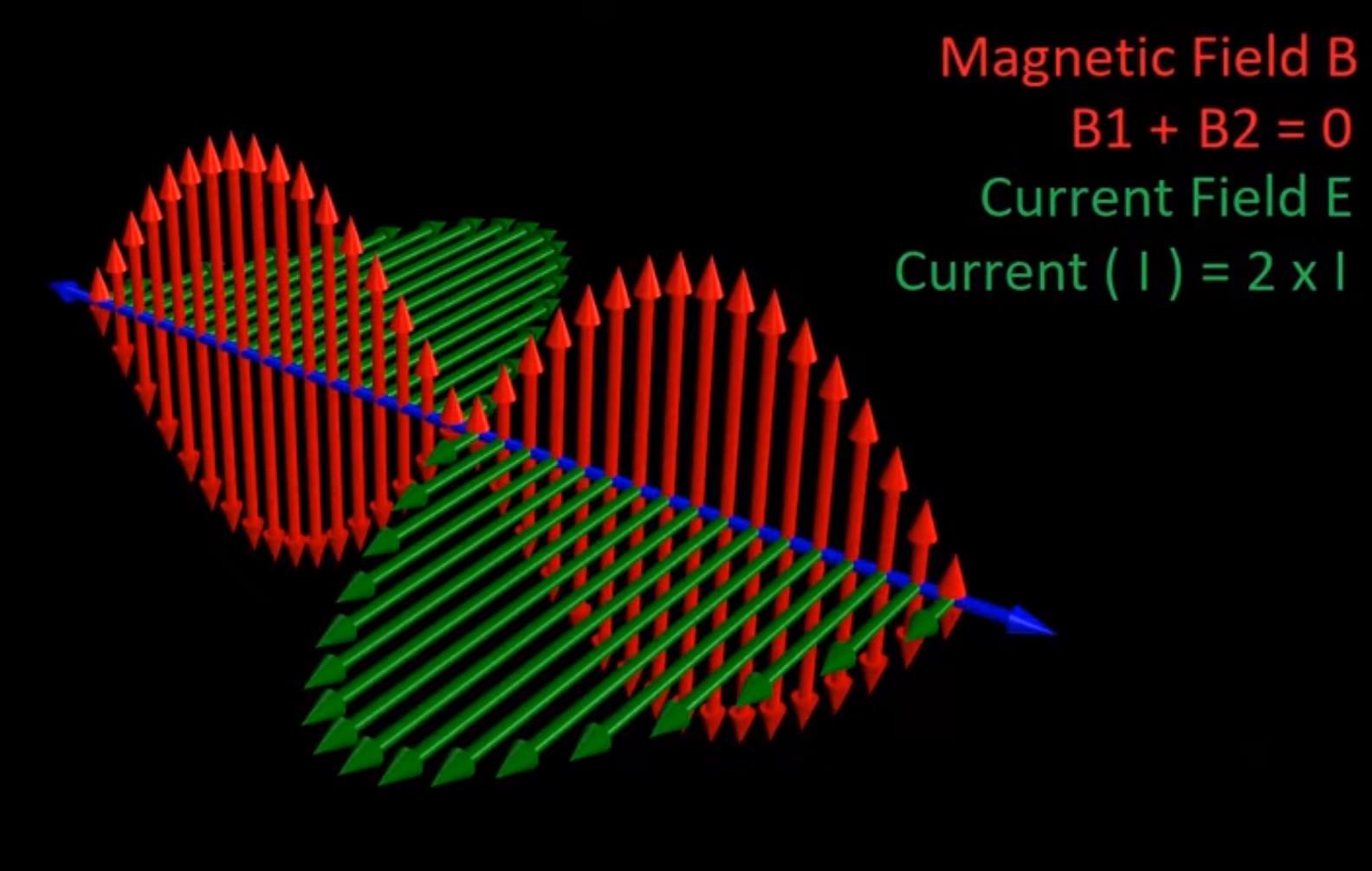
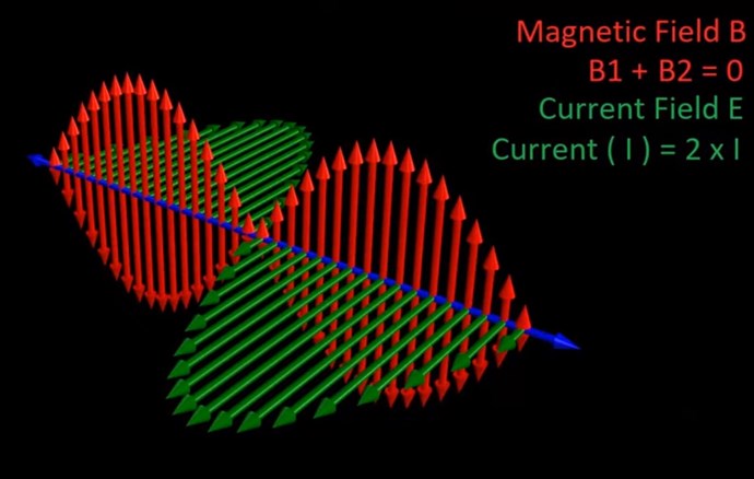
Now, a Right Hand Rule both facing Inwards, it is the same as:
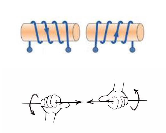
Why? Why must we have Opposing Magnetic Fields?
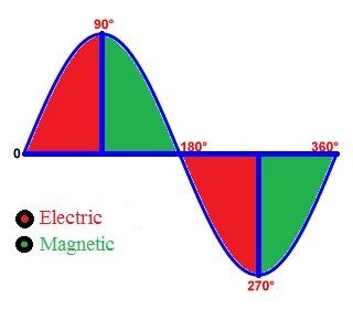
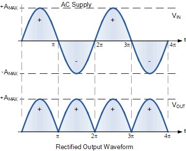
If the directions of the two signals are such that opposite H-fields cancel and E-fields add, an apparently steady E-field will be created. The energy density of the fields remain as calculated above, but the value of the E-field will double from E/2 to E.
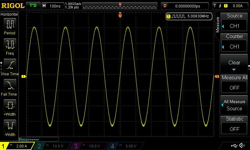
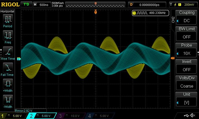
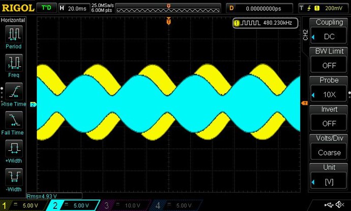
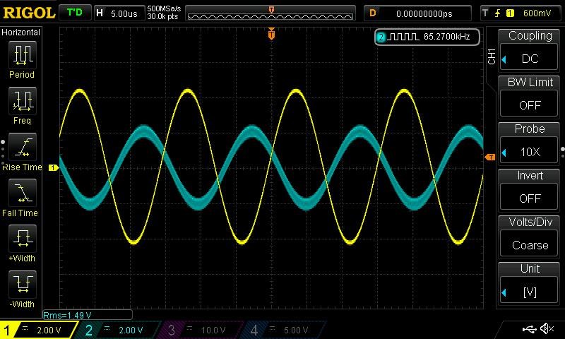
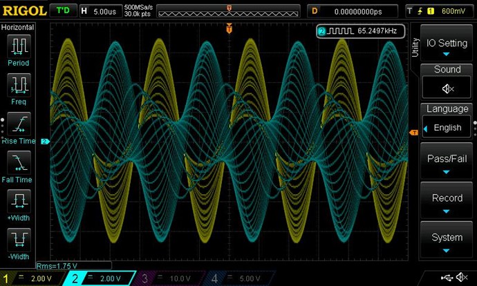
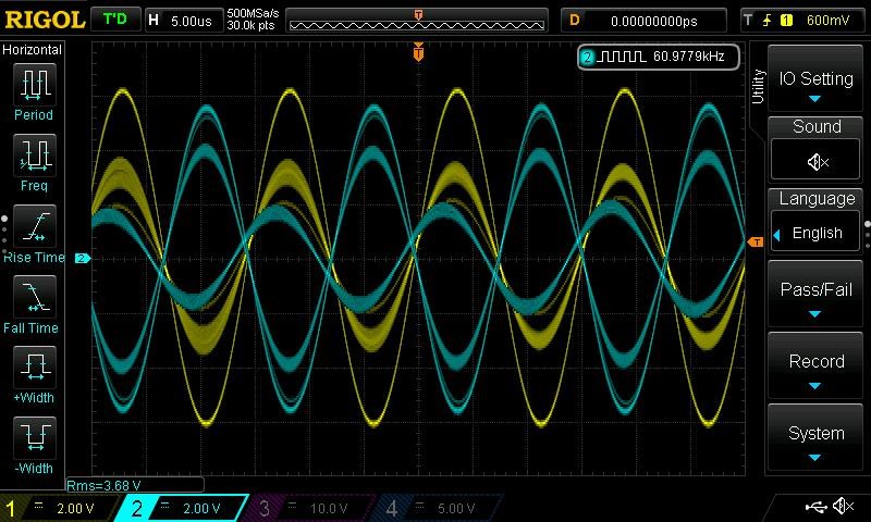
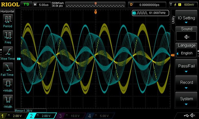
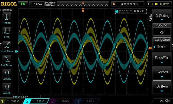
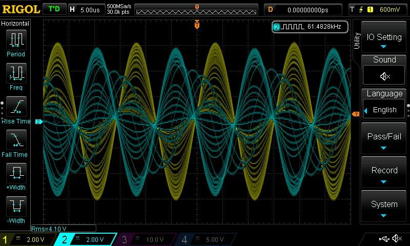
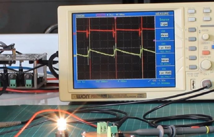
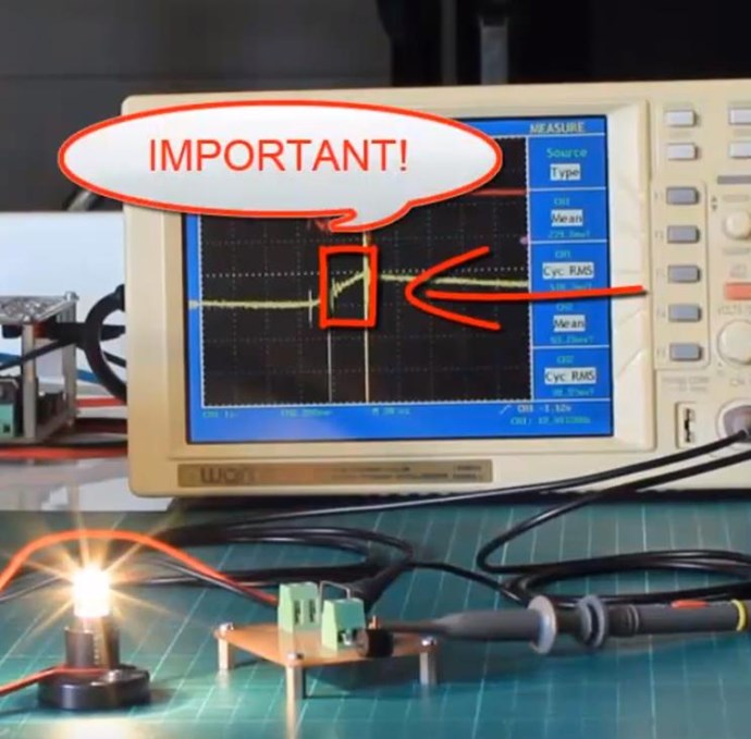
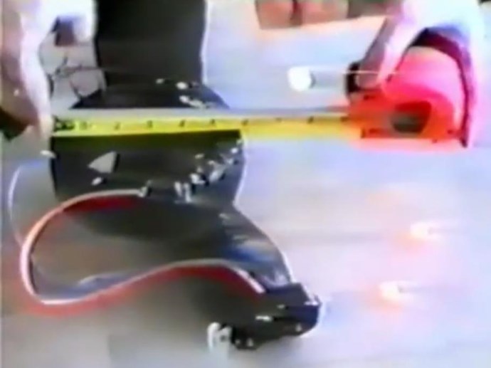
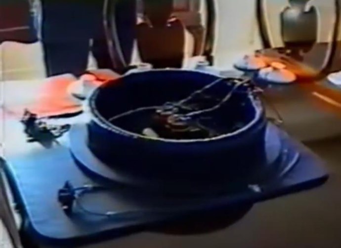
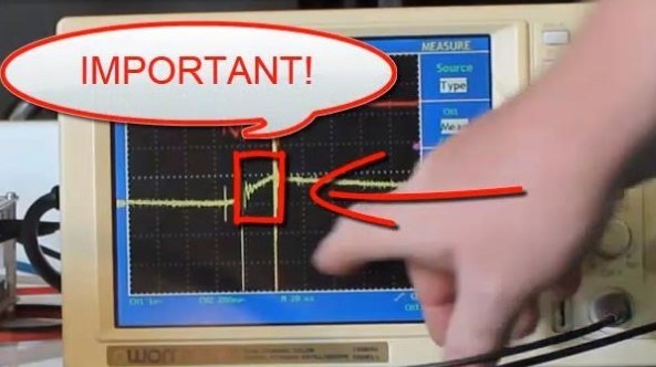
By Opposing the Magnetic Fields in a Dynamic System, the Electrical Field doubles! The Mr Preva Experiment proved this to be true!
Floyd Sweet also said:
Current is deemed as a quantity or number of charged particles moving from P1 to P2 in time t, or as the charge transferred in one second by a current of one ampere. The coulomb is the charge on 6.24 x 10¹⁸ electrons. Electric fields are due to the presence of charges. Magnetic field effects are due to the motion of charges. Current is the net rate of flow of positive charges. This is a scalar quantity.
In the specific case of positive charges moving to the right and negative charges to the left, the effect of both actions is positive charge moving to the right. Current to the right is: I = da+/dt + da-/dt. Negative electrons flowing to the left contribute to the current flowing to the right.
The Mr Preva Experiment also proved this to be true!
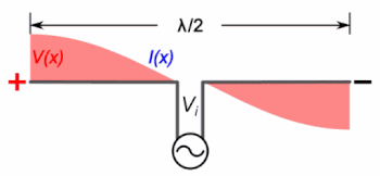
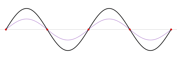
We see a Standing Wave of Magnetic Fields!
This thread is for those with questions, thank you Vasile for the following question.
Chris


.jpg?width=50&crop=0,0,50,50)


 --
--