Chris
posted this
13 November 2023
- Last edited 14 November 2023
My Friend, you are very welcome!
This knowledge you have gained has the potential to change the world! You are one of the Leaders, ahead of the pack, and others will look up to you and others here, for guidance, when they start their journey.
Thank You! Thank You for being a Good Hearted Human Being, that wants to stand up and lead the change coming!
I am more than happy to help you and others that put in the effort! I will support you the best I can, always!
I need to warn, there are a lot of Scum Sucking Filth, Shills out there, so beware of their games, tactics and idiot behaviors, they will mislead, distract and try very hard to lead you away from the truth! OMG we have struck a lot of Complete Idiot Shill Plagiarist, filthy Human Beings, a total Disgrace to the Human Race! Real Scum!
That aside, we have so much potential, we are world changing, world leading, Researchers! We are doing things that others have only ever dreamt about, many never ever even coming close to the truth! We have experiments that show things that no one else has ever achieved!
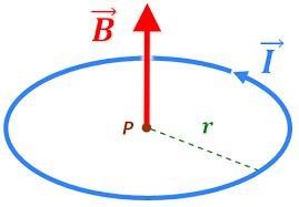
The Magnetic Field, under a State we know how to Invoke, and shared freely, Compressed, becomes a Charge Pump, it Frees and Accelerates Charge, down the Wire. The more Stress, Compression we invoke, the More Charge is Freed and Accelerated!
It is very very simple, but we must train our minds to think about this entire field in the Correct Way! Currently, Science does not teach the Truth in this field! It is vague and full of fantasy! We all have to force our minds to think simply, on Simple things, because this is NOT Hard! Its Really Not!
We have corrected the missing gap in Human Evolution, the gap that was deliberately inserted, by very evil people! Once you have a few very simple experiments under your belt, you will see, clearly, how simple, how cheap, how absolutely essential, this very basic Science is!
Best Wishes,
Chris


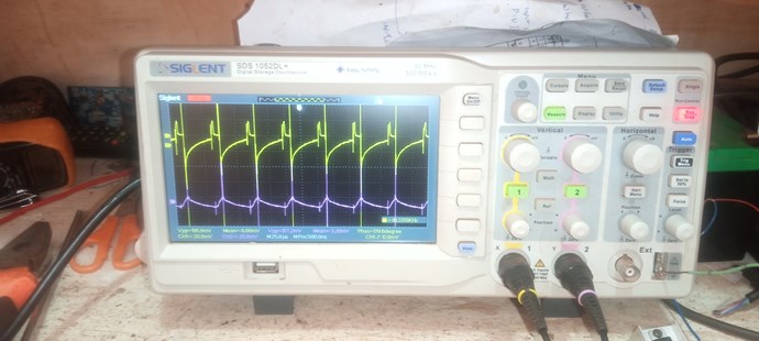


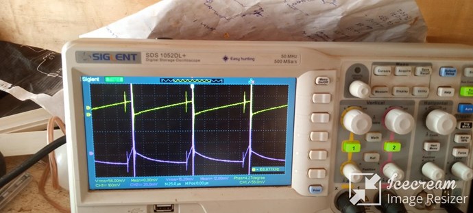

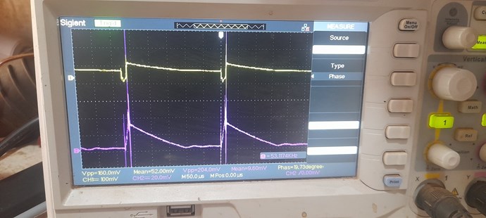
.jpg?width=690&upscale=false) I have a delay circuit that switches on L3, yellow trace is the pulse to the mosfet gate that switches L1 and the purple is the pulse to the mosfet gate that switches L3.
I have a delay circuit that switches on L3, yellow trace is the pulse to the mosfet gate that switches L1 and the purple is the pulse to the mosfet gate that switches L3.
 but it's tuned on "no delay" for now as shown below.
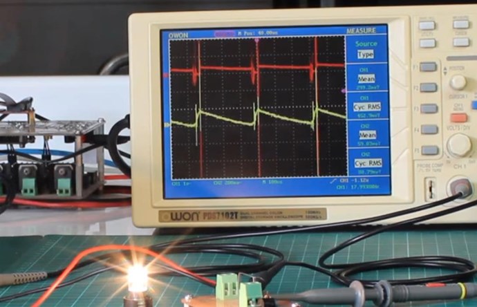
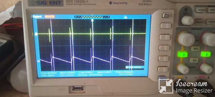
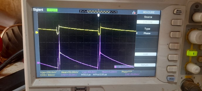
 Now moving the probes and looking at the currents through L2 and L3
I get these waves after some tuning, yellow trace is L2 and purple trace is L3.
Now moving the probes and looking at the currents through L2 and L3
I get these waves after some tuning, yellow trace is L2 and purple trace is L3.
 The sawtooth wave is not good here, the linear decrease on L3 is too fast, In an effort to get it better I tried many adjustments on input voltage frequency and duty cycle with no success, but when l grounded my scope i got a better sawtooth wave on L3.
 Iam i moving in the right direction? Please advise on what voltage value is to use RMS,Peak to peak or Mean?
Chris and the team thanks for sharing knowledge.
Iam i moving in the right direction? Please advise on what voltage value is to use RMS,Peak to peak or Mean?
Chris and the team thanks for sharing knowledge.


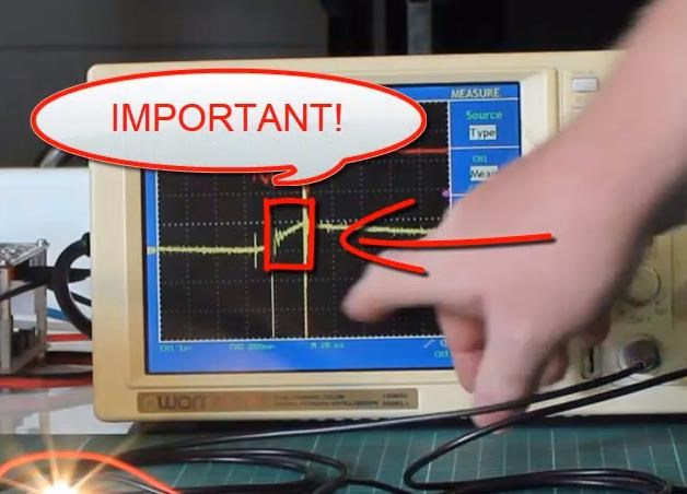
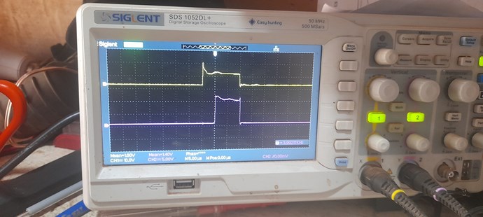
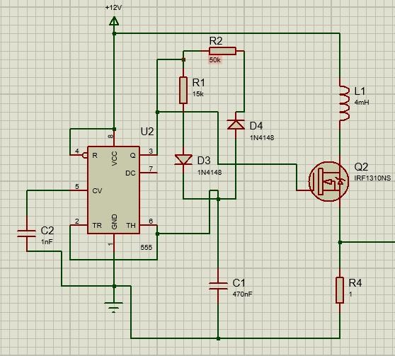
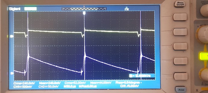
.jpg?width=690&upscale=false) After some adjustments on frequency, dutycycle and input voltage, I got the best sawtooth wave so far, the linear decrease ends at the right point at the end of the cycle and the input current drop effect was present.
After some adjustments on frequency, dutycycle and input voltage, I got the best sawtooth wave so far, the linear decrease ends at the right point at the end of the cycle and the input current drop effect was present.
.jpg?width=690&upscale=false)
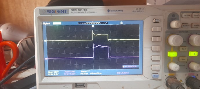
 Observation:
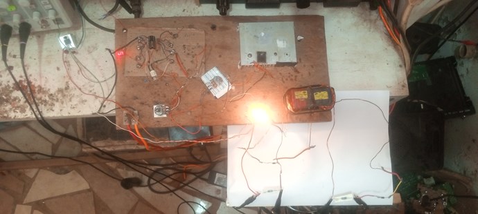
Switching in L3 i observed that the current iam measuring through L2 does not change. But the input current on the power supply drops.
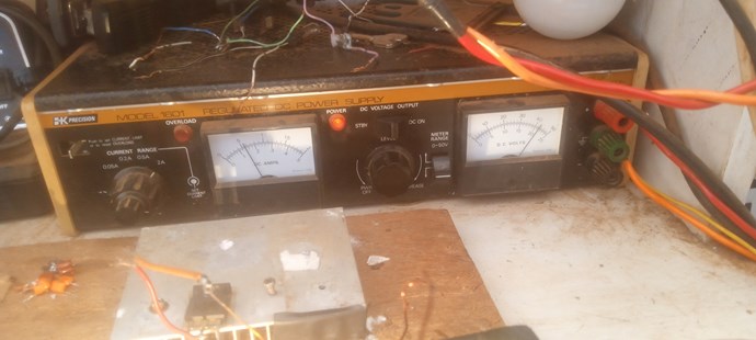
And the input current from the DC power supply powering the whole circuit is around 500ma.
The purple trace is showing current through L1 8volts across the resistor giving 8A !.i think its a wrong reading, please advise.
Observation:
Switching in L3 i observed that the current iam measuring through L2 does not change. But the input current on the power supply drops.
And the input current from the DC power supply powering the whole circuit is around 500ma.
The purple trace is showing current through L1 8volts across the resistor giving 8A !.i think its a wrong reading, please advise.
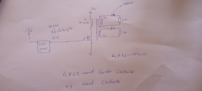
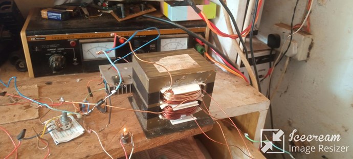
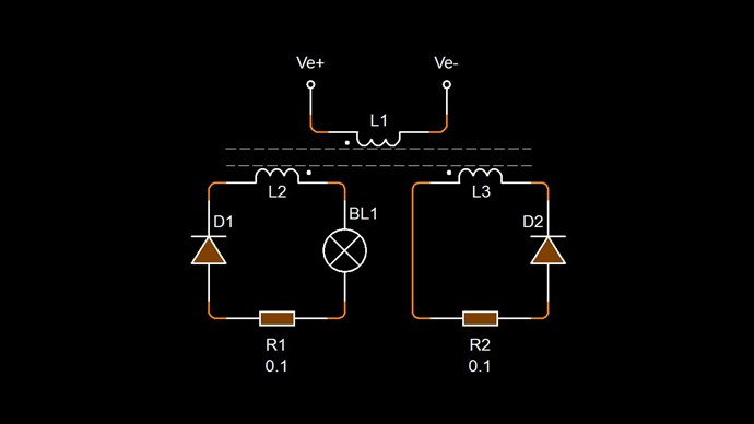
 This is just for illustration how iam measuring the current through L1, R4 is the current sensor. Iam using a gate driver which is not included in shematic above.
.jpg?width=690&upscale=false)
.jpg?width=690&upscale=false)
.jpg?width=690&upscale=false)
.jpg?width=690&upscale=false)
-(1).jpg?width=690&upscale=false)


