The MrPreva Experiment

  • Topic Is Sticky
  • 18K Views
  • Last Post 30 November 2022
admin posted this 23 March 2017

I think this is perhaps one of the most important experiments anyone could do! A huge amount of information can be learned by running this very simple experiment!
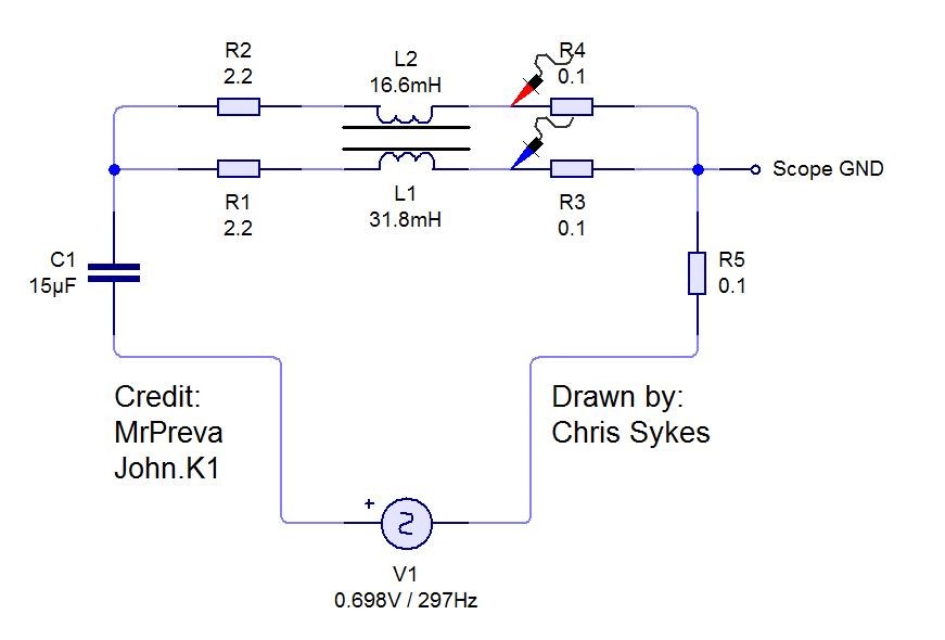
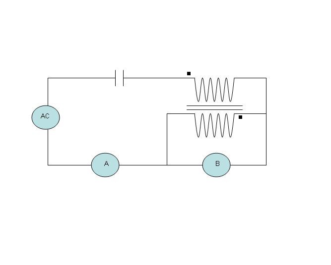
The MrPreva Experiment Circuit

Please Note: The Current's (I), add, Floyd Sweet talked about this specifically:

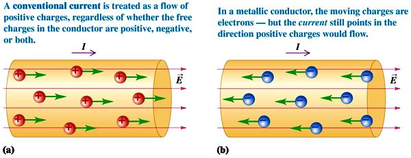
In the specific case of positive charges moving to the right and negative charges to the left, the effect of both actions is positive charge moving to the right.

Current to the right is: I = da+ / dt + da- / dt.


Negative electrons flowing to the left contribute to the current flowing to the right.


The total Current, is the Sum of the both Currents!
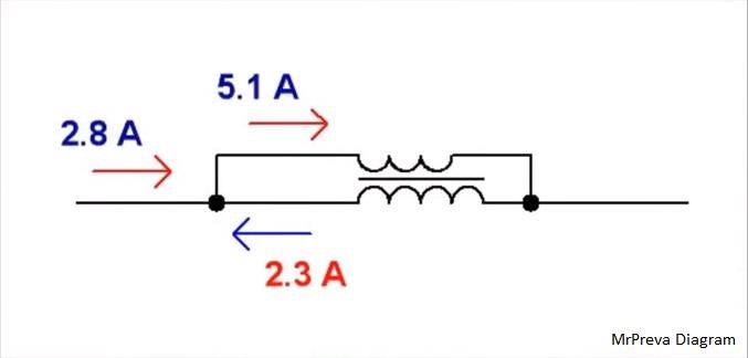
 

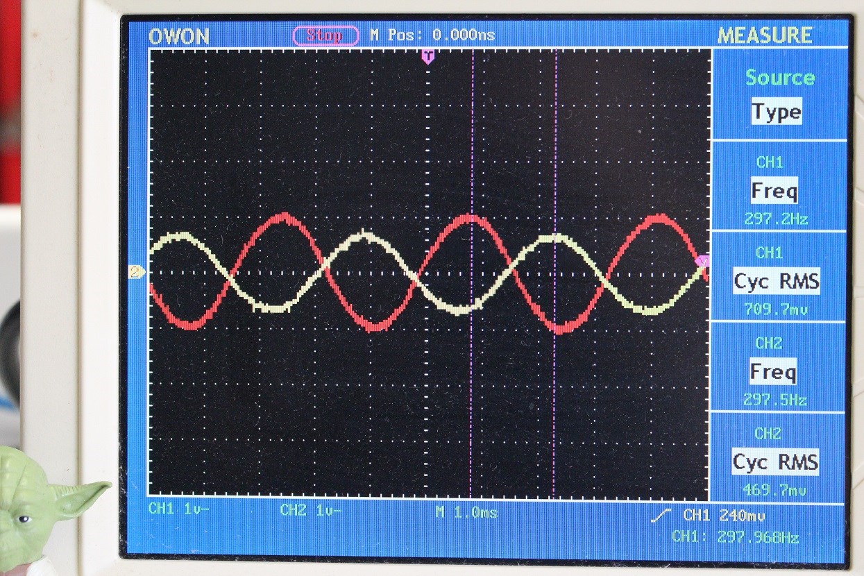
We see, 2.8 Amps (da+ / dt) + 2.3 Amps (da/ dt) = the shown: 5.1 Amps as Floyd Sweet told us.

We see a Negative Power Factor, where the Voltage (V) Current (I) are out of phase by a Degree, which results in a Negative Power Factor!

cos(theta)

Where theta is the Phase angle in Degrees. EG:

cos(180) =  -1


You will see there are some problems with the MrPreva Circuit, and it is explained, because, the Current (da- ) has become a Generator, or a Battery, which is the only time  Kirchhoff's Current Law does not hold in an applied situation. 

Order By: Standard | Newest | Votes
Chris posted this 26 March 2017

Cd_Sharp, this is excellent! Thank you for sharing!

Some very simple observations shot:

  • One Globe is very much brighter than the other!
  • The other Globe, although illuminated, has a lot less Current through it!

This is such an important experiment! I wish people out there could see that have not done the experiment! I have done this experiment several times and learnt a bit more each time!

I think I might re-do this experiment for the Forum also!

Some data on my Coils:


Input:
Period: 3.320
Offset: 0.160
Degrees: 17.3
Active: 2.203788426168
Apparent: 2.30821
Reactive: 0.686403717929
Power Factor: 0.9547608


L1:
Period: 3.320
Offset: 0.28
Degrees: 30.4
Active: 8.0004243646859
Apparent: 9.275707
Reactive: 4.6938212608966
Power Factor: 0.8625137


L2:
Period: 3.320
Offset: 1.72
Degrees: 186.5
Active: -6.1948770793364
Apparent: 6.234956
Reactive: -0.7058169710592
Power Factor: -0.9935719

My Turns:

L1 Turns: 175
L2 Turns: 88

   Chris

parkham posted this 08 June 2017

Hi.  I have a few questions:

Input voltage / amps, how much?

Coil wire gauge?

What capacitor to use?


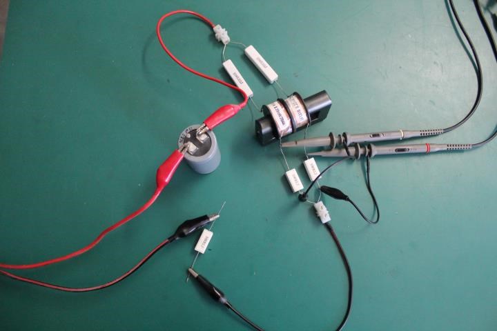
Also, what are each of the white blocks in your replication?  Can I see the entire picture?  Like what the wires are running to as well?  It's easier for me to see it, in addition to reading the schematic. 

Thank you,

Chris posted this 09 June 2017

Hi.  I have a few questions:

Input voltage / amps, how much?

Coil wire gauge?

What capacitor to use?

Also, what are each of the white blocks in your replication?  Can I see the entire picture?  Like what the wires are running to as well?  It's easier for me to see it, in addition to reading the schematic. 

Thank you,

Thanks for the questions Parkham!

The Blocks: Ceramic Power Resistors, 2.2 Ohms for the big ones 10 Watts, 0.1 Ohms for the smaller resistors, 5 watts.

I just used what I had laying around. Just experiment with it till you get the best result. All my wave's measured were sine wave, so no problem with transients.

My Coil turns:

  • Turns: 175
  • Turns: 88

Note: Turns N, with Current I, equates to the Magnetic Field B, so more turns is better most of the time, just up the Voltage so more Current can flow. The reason I say this, is, its possible to have an experiment where the total Magnetic Field is in sufficient to induce an EMF across the second coil and the Input Current dominates! This means a failure!

This is such a simple experiment, and so much can be learned, if done properly! One can learn a lot about Negative Power Factor, this experiment is the basis for Electromagnetic Induction! Electrical Transformers Work on these exact same technologies!

For someone to say "This experiment does not work", is basically saying that Electromagnetic Induction does not work!

An example of this sort of stupidity:


This is Tinman's effort to replicate the Mr Preva Experiment. It simply is embarrassing! He is saying that Electromagnetic Induction does not work!


After a lot of Down Votes and pressure from people with brains, Tinman tried again, and still failed. Again saying Electromagnetic Induction does not work! Tinmans colleague, Itsu, has however done some excellent work! Showing that, Indeed, Electromagnetic Induction does work as has been stated for some 187 Years, and do in-fact have a valid Law in Nature, thanks to Michael Faraday:

   MrPreva replication 1 :


   MrPreva replication 2 :


   MrPreva replication 3 :


   MrPreva replication 4 :


   MrPreva replication 5 :


  • Liked by
  • Augenblick
Zanzal posted this 09 June 2017

Hey Chris,

I've not tried the MrPreva experiment as I was fairly certain by looking at it that it would not function if pulsed dc was used to drive it directly (without an inverter) and I don't mess with anything AC. Can you (or anyone else) confirm this assumption?

  • Liked by
  • Chris
  • Augenblick
Chris posted this 09 June 2017

It is a RLC Resonant Circuit, the Cap and Coil Combination are tunned for RLC Resonance.

So DC Pulsing is possible, an Audio Amp driven with a Sine Function Generator is also another good way to do it, I used this method.

As long as the Cap and Coil are in RLC Resonance, then it doesn't matter what the Circuitry is. Switched DC 50% Duty will be difficult to get RLC Resonance depending on the Circuit, so the Audio Amp is a good way to go.

   Chris

  • Liked by
  • Augenblick
  • cd_sharp
parkham posted this 09 June 2017

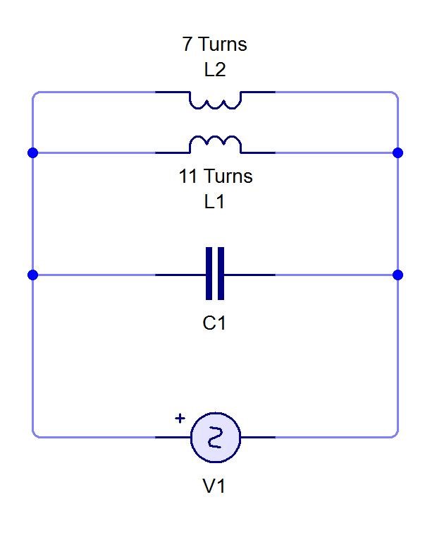
I'll check the videos, thanks.  I was going to attempt replication using the exact figures on the first diagram - 7 turns and 11 turns before doing any further experiments.  If I do that, any suggestions on what I asked about earlier?

  • Liked by
  • Augenblick
Chris posted this 09 June 2017

I'll check the videos, thanks.  I was going to attempt replication using the exact figures on the first diagram - 7 turns and 11 turns before doing any further experiments.  If I do that, any suggestions on what I asked about earlier?

My only suggestions, same as before:

I just used what I had laying around. Just experiment with it till you get the best result.

Learning is a ton of fun, this is still today one of my favourite experiments! So simple, so Valuable!

Please remember, Floyd Sweet said:

In the specific case of positive charges moving to the right and negative charges to the left, the effect of both actions is positive charge moving to the right.

Current to the right is: I = da+ / dt + da- / dt.


Negative electrons flowing to the left contribute to the current flowing to the right.

   Chris

  • Liked by
  • Augenblick
Chris posted this 25 July 2017

To properly reference this thread, I would like to Cite the Reference:

Please see: The Rotary Transformer - Tinman for information on how this very simple Circuit can be used in Above Unity Applications!

We now have busted the door wide open!

   Chris

  • Liked by
  • Wistiti
  • Augenblick
Zanzal posted this 27 July 2017

I've had similar issues with my probes interfering with the circuit, so I just started using 10x and it seems to have helped with that. If your probes have a switch for a 10x setting then you might try that, just make sure your scope knows the connected probe is set to 10x (don't forget to check probe calibration after switching).

  • Liked by
  • Chris
  • Augenblick
Chris posted this 28 July 2017

Hey Cd_Sharp, Zanzal - Excellent!

Cd, nice setup! The time rate of change is key, of the Magnetic Fields, and if there is not a gradual Rate of Change then yes there can be a lot of funky stuff happen.

For example, a Sine Wave has a gradual change over time, but a Square Wave has a fast Rise and Decay time with a DC (Off Time) in between. This is where the Coils see no relative change. However in saying this, the Current in the Coils do take time to build, ramp up and this can give a similar effect. The following video is an excellent example of what I mean:


Each little rectangle under the curve is a Change in Time. Lots of small ones with small changes is a gradual Change in Time.

I hope this helps some, I found this helpful when I was studding this. This is why the Cap helped in the Brightness of the Globes...

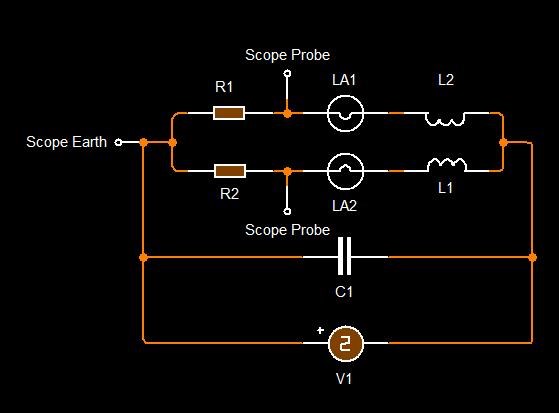
Scope and the connection, I would only guess there may have been a Ground Loop, shorting somewhere, through the ground connection.

Your two Ground Clips need to be on the same branch. Same piece of wire at the same place. Then you should be ok, unless there is something else going on.

Something like this:

Your Globes are both different brightness's so that is an indication that the Currents are greater in one Branch that the other!

Youre right, this is a very important experiment! If there is anything to be learned, this experiment can show you! It is simple, cheap and very easy!

   Chris

  • Liked by
  • Augenblick
Chris posted this 28 July 2017


Cd, Zanzal,

At any one point in time, the Coils in the MrPreva Experiment, Buck Each Other!

They Oppose!

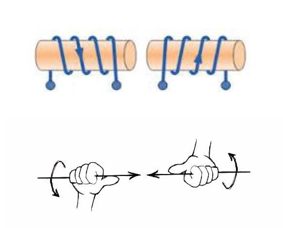
This results in a Gain, in the local Circuit, of almost twice the Current. Try to picture the Magnetic Fields, what they are doing, the Currents, and why they Oppose... Right Hand Grip Rule...

Then look at the other devices, like Don Smith:

For some reason, we, the human mind, has a tendance to way over complicate the simple, We need to force our minds to think simply!

   Chris


Zanzal posted this 28 July 2017

A couple of thoughts about this experiment:

AC appears to work better than DC. Chris mentioned time rate of change, but I think that's only part of the reason. With AC the circuit is never really "open" (maybe twice per cycle at the beginning and mid points when voltage is zero), but DC pulsed by design opens and closes the circuit and I think this reduces the effect also.

If I am remembering correctly from some weeks ago when I watched the videos, initially both lamps seem to light up about the same, but over time a reverse current builds up along one path causing that path to become a source in parallel with the main source. Not only is the current reversed, but it is self sourced meaning that it becomes its own source.

The experiment does provoke a lot of thoughts on the nature of energy. We all know Ohm's law, V = IR, but has anyone considered that V = J/C (Joules per Coulombs) which is J/C=IR, and that C=I (or Amps per second) which means this can be re-written as J=I^2R. Is V nothing but a manifestation of I^2R? (As a side note, this equation is also the same as the heat in Watts dissipated by a circuit so if you don't know it, you should memorize it for the future, you'll need it to estimate heat dissipation).

Has anyone ever considered why getting voltage is so easy, but most large voltage values are unable to move significant current. We know from the above that something must be missing. Ohm's law must be incomplete. If we can eliminate V and still be left with a missing set of behavior that can only be understood by measuring V. So what is that? V is only the current electrical pressure within the circuit in an open circuit, pressure can build so you can get high voltages even from very little pressure. You can increase the voltage using a transformer, but that voltage can't gain you any current without drawing it from the source.

So what does this have to do with Preva? Maybe nothing, but maybe the experiment proves you can break the rules temporarily even if in the end you never see that it happened unless maybe you question whether Ohm's law was broken.

Of course don't take my word for it. I've only ran the experiment once a few weeks back and on DC. At the time I ran I hadn't even considered these things and had no idea why it was important. This is just me sharing some random thoughts.

  • Liked by
  • Chris
  • Augenblick
Chris posted this 29 July 2017

We need to force our minds to think simply!

Nice one.


Hi Vasile - Of course I mean this in the nicest possible way!

Chris

  • Liked by
  • Vasile
  • Augenblick
Chris posted this 31 July 2017

Excellent work there Cd!

Isnt this the best experiment! It is beneficial in so many ways! With the Magic of the Ocilliscope, we can Click our Fingers and Freeze Time! When Time is Frozen, we can look at the Current, and the Coils, and we can use the Right Hand Grip Rule to see in what direction the Magnetic Fields are. You should end up with this:


 This is the beauty of Science, we have most of it correct, we just need to fix some mistakes, typically the assumptions made.

I too am guilty of assumptions sometimes, but I realise that my assumptions are not proof!

   Chris

  • Liked by
  • Augenblick
Chris posted this 04 August 2017

Hey CD, the Bulbs likely are pulling more current than the core can handle, the core will be saturating and as a result the globes change the Sine Wave.

The core might be a low saturation core. Its normal. The Sine wave looks like its got sharp peaks at the top and bottom and not much in between?

Really nice job CD!


  • Liked by
  • Zanzal
  • Augenblick
Chris posted this 12 August 2017

Another successful replication of the MR Preva Experiment from someone we are all familiar with: TheOldScientist


If you think careful about the Currents an how this device needs to be in RLC Resonance you will see something really amazing!

When the Coils are in RLC Resonance the current in each coil has a propagation relationship. This as pointed out in the title. Wave Propagation theory is well worth studding. This will make more sense after the video:

.


When the Wave propagates, there must be 1/2 Wave Length as mentioned in the video, for efficient Wave propagation.

   Chris

  • Liked by
  • Wistiti
  • Augenblick
Chris posted this 13 August 2017

Hi CD - Very interesting question with some more interesting results!

Some rough math on my setup above, shown below:

L1: 31.8mH
F = 1/2 Pi Sqrt(L C) = 1 /  2 * 3.14159265358979 * 0.00069065186599328 = 230.44 Hertz, So our result is not far away, including the Damping Factor ζ (zeta) 297 Hertz


L2: 16.6mH
F = 1/2 Pi Sqrt(L C) = 1 /  2 * 3.14159265358979 * 0.000498998997994986 = 318.948422204035 Hertz

I simply did not take this far enough, this was quick and dirty guesses with no verifications at all. I did not check L1 - L2 = Lprime as the Inductance for the equation, although I should have...

Why should I have done that? Because each Inductance will cancel... Maybe we could do this here?

Either way, we are still some ways out from the resonant frequency even with the Damping Factor.

Edit: Oddly, if I half each inductance, then add the two, I get: 264.16Hz

   Chris

  • Liked by
  • Augenblick
alohalaoha posted this 13 August 2017

Successful replication by Kirill Anashenkov  - 30W ferroresonance flash-light with same type of MR.PREVA coils inside ferro-resonant pot. Device has worked whole night and finaly burnt from primary coil to components. Seems energy time dependent like Sweet vta and Stiven Mark - tpu. Correct schematic is in Kirill's video.

Сердечники из магнитных материалов

https://lib.chipdip.ru/245/DOC000245900.pdf

Основные характеристики магнитомягких ферритов

https://lib.chipdip.ru/245/DOC000245902.pdf


p/s. Автор Кирилл АНАШЕНКОВ:
"Это называется ферро-резонансом сердечника. Действует контур L1-L2. Конденсаторы желательно подобрать ближе по значению (электролиты). Вначале горел не долго-пару минут. Затем поднимал кондер 100 пФ, и менял обмотки-тем самым добиваясь наилучшего (максимального) - но неискаженного отношения частоты-амплитуды на нижнем электролите. После запуска левая половина схемы с ТЛ494 - не работает уже. Дроссель служит от изоляции синдрома 50 герц. Далее светил час, а потом добился большего - оставил на ночь... и трансформатор сгорел (первичка). Далее,в томительном ожидании деталей с Китая,забросил это дело на время. По всн у мея сдвиг на Теслу."

  • Liked by
  • Chris
  • Augenblick
alohalaoha posted this 17 August 2017

high jump MR.PREVA

anothercat posted this 05 November 2017

Hey guys,

I would like to point out that in the following video it's exactly the same phenomenon with slight differences:


I guess that the 2 secondaries are in bucking mode...

Chris posted this 05 November 2017

Hello Anothercat and Welcome!

Excellent Video thank you for sharing!

   Chris

  • Liked by
  • Augenblick
blackboarddd posted this 06 November 2017

Hello everybody, maybe mine is a silly question but are the two coils wound in opposite directions?

Thank you

Chris posted this 06 November 2017

Hello and welcome Blackboarddd!

By experimenting with the Coil winding direction, you will find there is one way that works best in this configuration. I suggest increasing the turns to a greater number, making a little more work, but it is easier to get a result and learn from this very valuable experiment.

The Magnetic Field (B), changing in time (dt) in the proximity to the Turns (N) is the catalyst for Electromagnetic Induction. With Few Turns one will need a great Magnetic Field at High Frequency.

   Chris

  • Liked by
  • Wistiti
  • Augenblick
Wistiti posted this 06 November 2017

Hi Blackboarddd! Don’t worry to ask; there is no silly question!

  • Liked by
  • Chris
  • Augenblick
blackboarddd posted this 06 November 2017

Thank you for your welcome and answers!

Can't wait to start testing, anyway my guess is the windings should be opposite...

Zanzal posted this 06 November 2017

Can't wait to start testing, anyway my guess is the windings should be opposite...

Yes, the windings in the Mr. Preva setup oppose. IMO, this experiment works much better with AC than it does with DC.. Pulsed DC results are a little fickle and while you'll still see one lamp brighter than the other, it may be harder to measure what's going on or determine if you are in resonance. With AC it will be much more obvious and you'll see the two coils are completely out of phase (when in resonance).

  • Liked by
  • Chris
  • Augenblick
blackboarddd posted this 07 November 2017

Thank you Zanzal for the hint. Which core material do you suggest to use for the inductor?

Regards

Zanzal posted this 07 November 2017

Thank you Zanzal for the hint. Which core material do you suggest to use for the inductor?

I think some of the videos the core was said to be nanoperm. I've not personally tried successive testing with the same setup varying only the core material so I've got no insight into it.

Chris has recommended others to use whatever they have handy - this is the best advice I could offer you. I've asked Chris several different times and different ways and what I've learned from him is that there are no magic core materials but there are sometimes bad core materials that can cause an experiment to fail. If you have trouble with one core material, you might document it and try another.

Wistiti posted this 22 November 2017

Hi team!

I have find a simple to build device that use the same concetp...

http://overunity.com/12487/simple-to-build-isolation-transformer-that-consumes-less-power-than-it-gives-out/#.WhV-mWeotaQ

Does someone here have already replicate it? I think i will give it a try when the time permit...

Chris posted this 22 November 2017

Hey Wistiti - I have build variants as you know. Youre right, this device is very similar to the Mr Preva Experiment:


Voltage is a quantity, as is Current, Electromagnetic Induction is a process that Transforms Voltage and Current. However, as we both know, this is not terminology that accurately describes the process!

Electromagnetic Induction produces a quantity of Voltage, which is E.M.F, Electromotive Force, it "Generates" or Pumps Voltage and therefore Current in the Second Coil. But this is not even entirely correct! Because this is a One to One process, less losses, we will always see a drop in total power. The Losses need to be over come by the Excess "Generation" or Pumping of Voltage and Current.

Current is Magnetomotive Force, M.M.F, and this Force needs to be off balanced by an Opposite force, to counter the One to One ratio less losses. In other words a Asymmetrical System instead of a Symmetrical System!

This is an old video, it was a year or so old when I posted it to YouTube. Its some of my early work:


Moving from a Square wave to a Sinusoidal wave is a start to seeing Energy Generation.

This is all stuff you already know, but for the other readers, they may find it useful.

   Chris

Wistiti posted this 21 January 2018

My trying of the Mr Preva the way Jacknoskills do.

Wistiti posted this 22 January 2018

If someone are interested to replicate here is photo of the transformer i use.

Please share your experiment!

Attached Files

Wistiti posted this 22 January 2018

Hi Vasile, thank you for your reply. If you look one post before the video I post, Chris post an image of the simple circuit I use. The capacitor is not needed.

For your information, I have not say it is over unity... Too much a big word! 

I have an oscilloscope, but not to familiar with it... need more time to learn with it... I also have a killawatt. The idea to share this experiment is to give to other the desire to do the experiment... it is really cheap and I think we can learn with it.

Hope I give you the desire to try it or any other Preva kind of experiment!

All the best!

Chris posted this 23 January 2018

Hello Wistiti,

Please consider that little curent in vs. more current out, does not necesarily mean what most people call ''Overunity''.There is also Voltage and the phase difference between Current and Voltage. Do you have an osciloscope? If not, the least you could get is a wattmeter. Now...by putting the wattmeter between the wall and your input you can get an idea of at least the power being put in. If u take the only consumer to be your bulb, than you could judge the power it has flowing thru it by its light intensity(at least for 50Hz is ok), but I would recomand an osciloscope.

Vasile

Hey Vasile, rightly pointed out, and if I may say, Wistiti is very aware already of this.

Learning to Amplify Current is perhaps the largest step forward. Wistiti has kindly shown this step forward along with others like CD_Sharp and others.

A Question, in your words, how would you describe this process?

   Chris

Antimony posted this 06 March 2018

I tried to make a sort of replication really fast today of this experiment, but i am not as knowledgeable as some of you others here, so i don´t know what to make of it.What should i look for?

I will go through the thread again when i get some time off to really get an understanding of the concept.

I haven´t did any coil measurements, or RLC matching, or anything like that. I just took what i had laying around, but i will in the future try to make it more like Chris has outlined in some of the schematics he has posted.

My L1 and L2 are thinner wire, and much more turns, + they are about the same regarding turns, mass and all that, but i saw that Chris had done that in one of the others he posted, so i went ahead.

I did get some cool synthesizer noises coming from it thou every time i sweep frequencies between 10-200 Hz, and the kids loved that.

The MrPreva Experiment Circuit

  • Liked by
  • Chris
  • Augenblick
Chris posted this 06 March 2018

Hi Antimony - Yes, re-reading and watching the videos will help make more sense of this.

Basically, we see the Current Double in the Circuit, thus the term used above increment of current. This is an Auto Transformer of types.

When youre happy this makes sense toyou, and if you need, please ask questions, then my next thread: Some Coils Buck n some Coils DONT will help with further understanding!

   Chris

  • Liked by
  • Antimony
  • Augenblick
Zanzal posted this 20 March 2018

Chris mentioned to me that very few people have taken the time to reproduce the Mr Preva experiment. Thought I'd share mine. Redid it real quick. This is not the AC variant so my waveform is not very interesting. Finding the resonance point for parallel resonance was as simple as dialing in the frequency into the lowest current draw. Here is what that looked like:

Attached Files

Chris posted this 20 March 2018

Awesome Zanzal - Thank You so much for sharing!

Please everyone, this is a very important experiment! Please take a few minutes to replicate this experiment, then one can take many long hours studying the Results! It is an invaluable Experiment!

Thanks again Zanzal! This is excellent!

   Chris

  • Liked by
  • Wistiti
  • Augenblick
Wistiti posted this 21 March 2018

nice, Professional looking, setup Zanzal.

Thank you for sharing your experiment!

  • Liked by
  • Chris
  • Augenblick
Zanzal posted this 13 April 2018

So this is a bit random, but I thought I'd post a experiment for those who really like the Mr Preva concept and are looking for something interesting to try: 

Would an induction heater be more efficient if two coils are used in a style similar to Mr Preva?

  • Liked by
  • Chris
  • Augenblick
Chris posted this 19 April 2018

Hey Zanzal,

Your question:

Would an induction heater be more efficient if two coils are used in a style similar to Mr Preva?


Answer to your Question: No, not as it stands.


@All Readers:

As we know the Mr Preva Experiment, is Symmetrical, it has equal and opposite Energy Transformations less losses. This is the reason it is, as it stands, Below Unity! Experiment shows: Current is Amplified, but we see a large Voltage Drop!

Electrical Energy is V x I, by loosing one and gaining another, does not constitute an Energy Gain! However, amplifying Voltage does not cost us anything! This is not a Transformation of Energy! No work is done to Step Up Voltage!

The next Step to The Mr Preva Experiment, is my Thread: Some Coils Buck and some Coils DONT

I introduce the Asymmetrical Energy Transformations, where the Input Energy is not affected, in anyway, by the Output Energy. This is the reason I have posted the Thread: Asymmetrical Regauging.

I see many are not seeing what I have been trying to show, many are not following the trail, not understanding posts I have taken time to detail effects and show where the open doors are. Its ok, I am ok if others do not want to learn.

However, if people want to learn how Energy Machines work, they will need to learn, need to start thinking in terms of Energy Transformations, learn how our Environment can introduce excess Energy!

Your Input of X Energy, is never, ever going to Transform itself into 2X Energy by itself!

You must Open a Door for the Environment to Add Energy!

The Door = Increasing the Rate of Kinetic Energy

   Chris

p75213 posted this 30 August 2018

Hi Chris,

Could you explain  "I = da+ / dt + da/ dt" . I know I = current. However I don't know what the rest is. Derivative of something with respect to time. da+ and da-.

  • Liked by
  • Chris
  • Augenblick
Chris posted this 30 August 2018

Hi P,

CD is right, da+ and da- is the change in Charges, both Positive and Negative Charges. If you have a look at the quote from the document, there is direct reference to Charge in the Conductor and its movement over time.

I have had a few people try to argue with me on this, trying to explain this away as nonsense, the funny thing is its a proof of concept experiment that can be done on the bench in 10 minutes.

There is only one site I have come across that has Current ( I ) depicted correctly:

Ref: http://33elec.blogspot.com/


All sites say a Capacitor has two charged Plates, one Negative and one Positive, but the depiction of Current is a singular entity with singular flow... Surely and misconception in Electronic Engineering that has been missed by the masses!

Reading this thread a few times and doing the experiment it all makes perfect sense. A logical sane mind can not argue with proof!

   Chris

  • Liked by
  • Augenblick
Marathonman posted this 30 August 2018

I agree. in the 1900 they found out current runs from - to + (JJ Thomson) but were to lazy to change it. i do not believe this as the misinformation was there to confuse your average person or researcher, this was done purposely. i have done my own tests that does prove it is so. while i still disagree on the whole electron thing and it's origin i will concur current does run from negative to positive. Negative is the Pressure, Positive is the non pressure thus will always flow to equalize. without positive non pressure current will no flow. 

Regards,

Marathonman

  • Liked by
  • Chris
  • Augenblick
Prometheus posted this 15 September 2018

A couple of thoughts about this experiment:

AC appears to work better than DC.

Square-wave AC works best in my testing. The effect is highly dependent upon the ratio of turns in the transformer vs. the frequency vs. the capacitance. It seems sometimes the magnetic induction overrides the ability of the voltage to push through both coils in the same direction, and sometimes it doesn't, dependent upon the parameters mentioned above.

If you get your capacitance and inductance just right (ie: hit a resonance point), you can get more current flowing through the second winding than flowed through the first (the second light is brighter). I'm unsure why it acts this way. Parametric resonance?

Marathonman posted this 15 September 2018

Could there be some forward biasing involved like that of a mag amp,  more so at certain frequencies.?

Regards,

Marathonman

  • Liked by
  • Chris
  • Augenblick
Vidura posted this 16 September 2018

Hi Prometheus,

Good to see new members joining to the forum ,participating and experimenting! I have also done some tests with the mr.preva experiment and similar circuits with diodes and found that the interaction between the coils and the timing can be changed by varying the parameters, although i have not found the explication yet.

  • Liked by
  • Chris
  • Augenblick
Prometheus posted this 17 September 2018

Ahaha! Here's a pretty good explanation:

We provide the "wind", the transformer is the "lake", the standing waves are the two current directions, but we're pushing the 'waves' high enough that they overflow the 'banks' of the 'lake'.

It's a rough analogy, but it helps to understand what's happening. I wonder if you had a center tap on each coil with a diode, connected to ground such that you could pull electrons in from ground? You'd have to drive it pretty hard to get the node of the standing waves below 0 volts such that electrons are pulled in from ground, but it could be done.

If it works, I propose we call it the "Moses" transformer (think of Moses parting the Red Sea).

  • Liked by
  • leonel
  • Augenblick
Jagau posted this 17 September 2018

If you re-read the beginning of this thread, you will understand how the MrPrevna experience works, which is the reality, please Moise that I respect should not be mingled with our discussion.


Jagau

  • Liked by
  • Chris
  • Augenblick
Vidura posted this 17 September 2018

Prometheus, The principle how the mr. Preva experiment works "normally" is straightforward, the current flowing in the direction of the coil with less impedance, and the opposed magnetic field makes the current in the other coil flowing backwards, I did understand that you could reverse the direction, which would be certainly a very odd behaviour.With the other direction I mean the lamp on the coil with more impedance would light brighter.

  • Liked by
  • Chris
  • Augenblick
We're Light Years Ahead!
Members Online:

No one online at the moment


What is a Scalar:

In physics, scalars are physical quantities that are unaffected by changes to a vector space basis. Scalars are often accompanied by units of measurement, as in "10 cm". Examples of scalar quantities are mass, distance, charge, volume, time, speed, and the magnitude of physical vectors in general.

You need to forget the Non-Sense that some spout with out knowing the actual Definition of the word Scalar! Some people talk absolute Bull Sh*t!

The pressure P in the formula P = pgh, pgh is a scalar that tells you the amount of this squashing force per unit area in a fluid.

A Scalar, having both direction and magnitude, can be anything! The Magnetic Field, a Charge moving, yet some Numb Nuts think it means Magic Science!

Message from God:

Hello my children. This is Yahweh, the one true Lord. You have found creation's secret. Now share it peacefully with the world.

Ref: Message from God written inside the Human Genome

God be in my head, and in my thinking.

God be in my eyes, and in my looking.

God be in my mouth, and in my speaking.

Oh, God be in my heart, and in my understanding.

Your Support:

More than anything else, your contributions to this forum are most important! We are trying to actively get all visitors involved, but we do only have a few main contributors, which are very much appreciated! If you would like to see more pages with more detailed experiments and answers, perhaps a contribution of another type maybe possible:

PayPal De-Platformed me!

They REFUSE to tell me why!

We now use Wise!

Donate
Use E-Mail: Chris at aboveunity.com

The content I am sharing is not only unique, but is changing the world as we know it! Please Support Us!

Thank You So Much!

Weeks High Earners:
The great Nikola Tesla:

Ere many generations pass, our machinery will be driven by a power obtainable at any point of the universe. This idea is not novel. Men have been led to it long ago by instinct or reason. It has been expressed in many ways, and in many places, in the history of old and new. We find it in the delightful myth of Antheus, who drives power from the earth; we find it among the subtle speculations of one of your splendid mathematicians, and in many hints and statements of thinkers of the present time. Throughout space there is energy. Is this energy static or kinetic? If static, our hopes are in vain; if kinetic - and this we know it is for certain - then it is a mere question of time when men will succeed in attaching their machinery to the very wheelwork of nature.

Experiments With Alternate Currents Of High Potential And High Frequency (February 1892).

Close