

I think this is perhaps one of the most important experiments anyone could do! A huge amount of information can be learned by running this very simple experiment!
Please Note: The Current's (I), add, Floyd Sweet talked about this specifically:
In the specific case of positive charges moving to the right and negative charges to the left, the effect of both actions is positive charge moving to the right.
Current to the right is: I = da+ / dt + da- / dt.
Negative electrons flowing to the left contribute to the current flowing to the right.
The total Current, is the Sum of the both Currents!
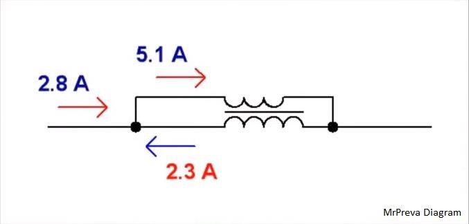
We see, 2.8 Amps (da+ / dt) + 2.3 Amps (da- / dt) = the shown: 5.1 Amps as Floyd Sweet told us.
We see a Negative Power Factor, where the Voltage (V) Current (I) are out of phase by a Degree, which results in a Negative Power Factor!
cos(theta)
Where theta is the Phase angle in Degrees. EG:
cos(180) = -1
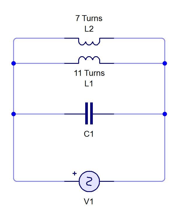
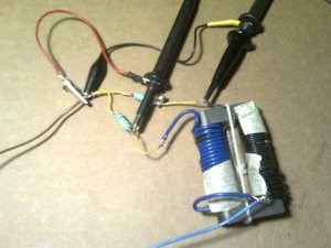
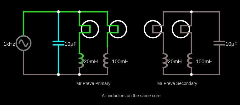
You will see there are some problems with the MrPreva Circuit, and it is explained, because, the Current (da- ) has become a Generator, or a Battery, which is the only time Kirchhoff's Current Law does not hold in an applied situation.


.jpg?width=20&crop=0,0,20,20 "fer123")


 version1
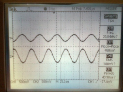 20KHz version1
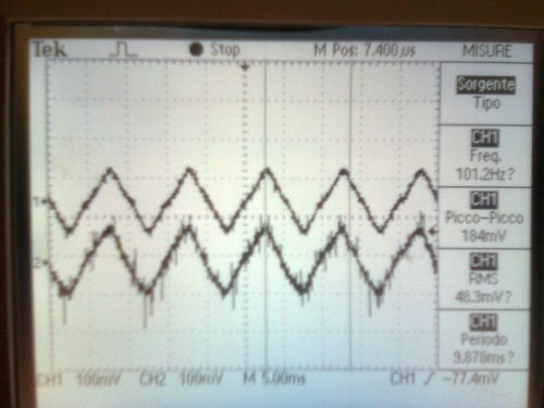 100Hz version1
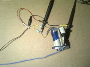
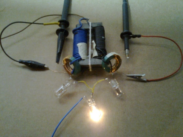
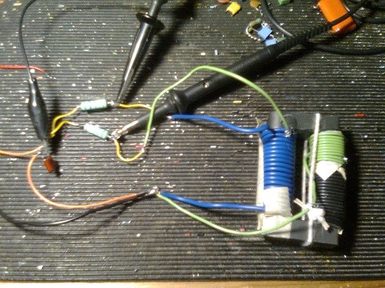 version2 sort of akula core
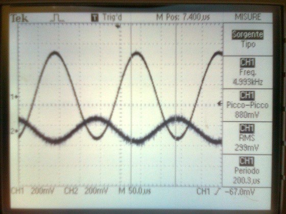 5KHz version2
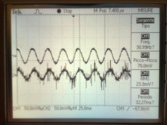 30Hz version2


 misuration 20turns coil
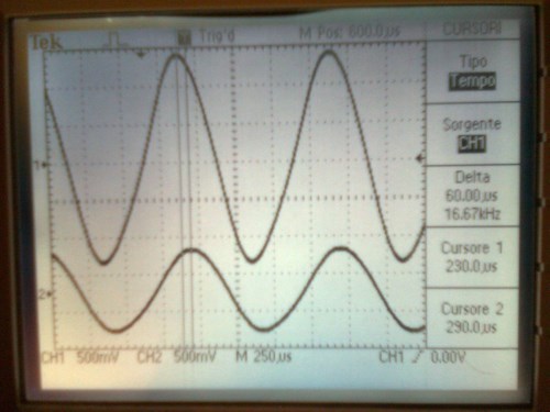
 misuration 40turns coil
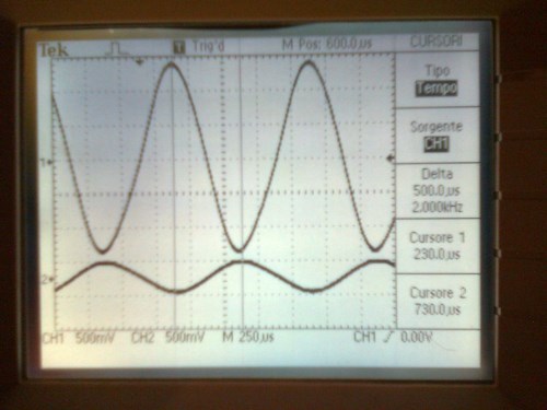
 misuration only currents shift
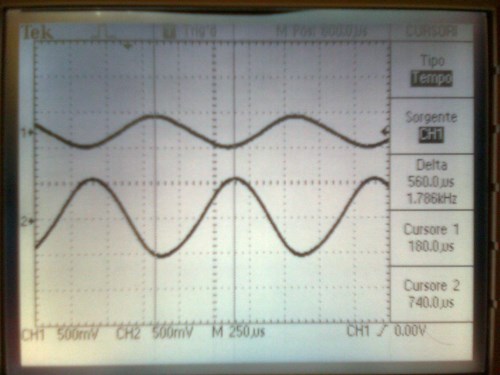
 hi!
hi!


 1
1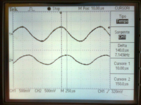 1
1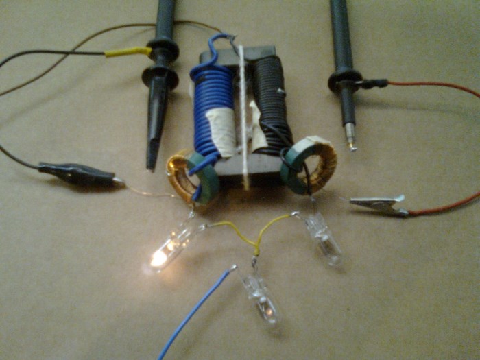 2
2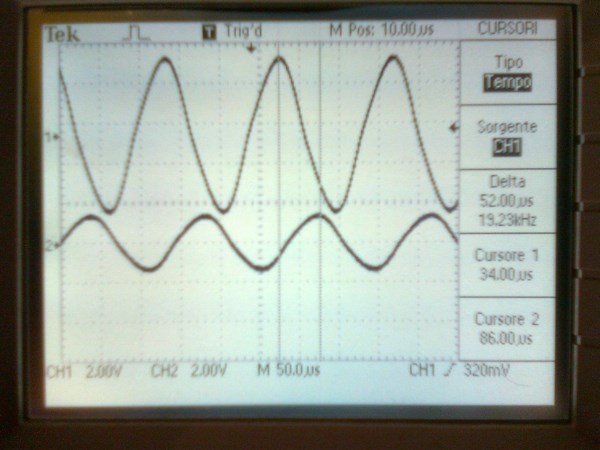 2
2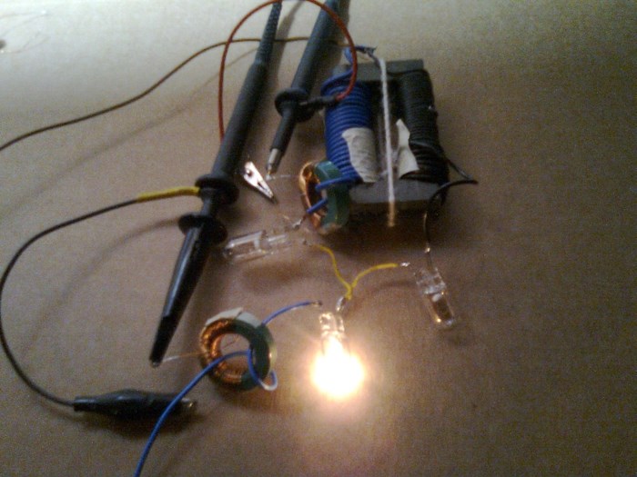 1A
1A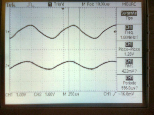 1A
1A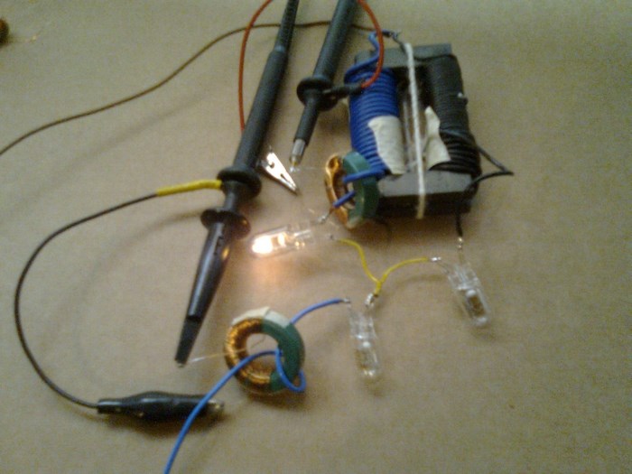 2A
2A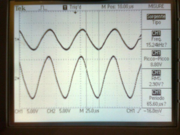 2A
2A


.jpg?width=690&upscale=false)
.jpg?width=690&upscale=false)
.jpg?width=690&upscale=false)
.jpg?width=690&upscale=false)

 and the good spirit of everyone here.


