GuruNandan's Experiment

  • 313 Views
  • Last Post 2 weeks ago
GuruNandan posted this 3 weeks ago

Hi Chris,


Thank you so much for this precious website and your effort! I really appreciate it!


I have gone through all the core concepts that you have shared on this forum.I hope that I am able to

successfully replicate the experiment.


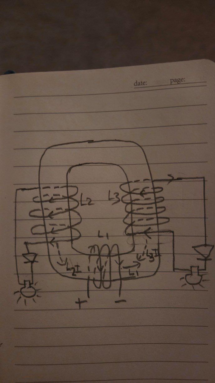
Could you please confirm If my understanding of the setup in the image is correct?

L1 is wound over L2. But for simplicity purpose I have shown L1 at the bottom side in the image.


Below is the sequence I have understood. Could you confirm if it is correct

  1. Current flows through L1 which generates magnetic field in the core
  2. L3I is the induced magetic field in the core which generates current through L3
  3. L2I is the induced magnetic field due to opposition to L3I and current flows through L2
  4. L2I is the induced magnetic which assists the magnetic field generated by L1

Attached Files

Order By: Standard | Newest | Votes
Chris posted this 3 weeks ago

Hello and welcome GuruNandan,

You are most welcome!

For the most part, yes your understanding is correct!

There are many examples here in these pages. The trick is getting the Voltage up Between POCOne and POCTwo, once you have Voltage, Current will be pumped. 

Best Wishes,

   Chris

  • Liked by
  • FringeIdeas
  • Drasko
GuruNandan posted this 3 weeks ago

Thanks for confirming Chris!


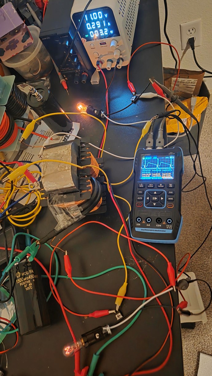
I have two setups currently. 1st with 320 amcc core and 2nd with 1000 amcc core.


For the 1st setup,


I have used 4 awg wire(2 turns) for primary and for poc1 and poc2 I have 150 turns of 18 awg wire opposing each other.

Here is the image below


I have 2 120V 6W bulbs as load

I am using zk-pp2k high power pwm


GuruNandan posted this 3 weeks ago


I have shared my YouTube video link above.

I am facing below issue:


In the video, left side load is connected to L2 and right side load is connected to L3

I get a sawtooth wave when only L2 is ON(Yellow wave on my oscilloscope)

As soon as I connect L3(blue wave on oscilloscope), my L2 load diminishes significantly .The yellow sawtooth wave dimishes.

Also, the L3 blue wave on oscilloscope never appears to take sawtooth form.It always stays a sqaure wave mimicking the input duty cycle.

I do not observe the effect where the L2 load brightens up or input current goes down significantly when L3 load is added.

I am stuck here for long. I tried increasing the primary windings turn to 8. But still no luck.

Could you please guide me further.


Chris posted this 3 weeks ago

Hey G,

Wind your coils once and leave them, do not take turns off or add turns, just leave then the way they are. This is really common and I do not understand why, 200 to 300 turns.

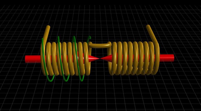
Its just a Polarity, the Polarity of the Coils, Primary injects a Voltage into POCOne, POCOnes Current Climbs because it is Loaded, the Change in POCOnes Current induces a Voltage in POCTwo, the Polarity is chosen so its not induced by the Primary, and because POCTwo's loaded, the Current Climbs in POCTwo.


POCOne and POCTwo must oppose each other, this is Asymmetrical Electromagnetic Induction.

I hope this helps!

Best Wishes,

   Chris

  • Liked by
  • Drasko
  • FringeIdeas
GuruNandan posted this 3 weeks ago

Hi Chris,


Thanks for responding. Trying to understand your post. You are saying that I need to increase the number of turns to 200 to 300 right?

You also commented about the polarity in your comments. I have used the exact diode directions shown in the image at the beginning of the post. Could please confirm that my diode direction is correct?


I'll incresse the number of turns.


Thanks!

Chris posted this 3 weeks ago

Hey G,

No, no, experiment with what you have, get the polarity's right, that's the main thing. Turns are secondary.

Remember, the Input is DC, this is a single, Polarity Specific Pulse, use the Right Hand Grip Rule, 3 coils, adding the polarities together: MMFPrimary + MMFSecondary + MMFTertiary = MMFPrimary.

You need to think beyond the current Symmetrical System: MMFPrimary + MMFSecondary = Zero.

The idea here is to learn the operation of the Coils and observe Asymmetrical Electromagnetic Induction. Get your POC Bucking, because the point is the Bucking. Bucking Pumps Current.

@Everyone - I dont have time for PM's! If you cant post to the thread, and work as a Community, then I do not do, one on one classes, through the PM's! Sorry I just dont have time for that!

Best Wishes,

   Chris

FringeIdeas posted this 3 weeks ago

Hey GuruNandan, looking good thanks for sharing.

A few things, if I may jump in here?

I would suggest maybe shorting POC3 instead of running a bulb there, and mostly monitor POC2 with the bulb. Reasoning behind my thoughts is if POC3 is shorted, the opposing flux going back toward the primary and POC2 is going to be much higher. I'm thinking this is going to make the effects more apparent. Someone correct me if I'm wrong.

Also, you make me nervous driving the primary straight from the zk-pp2k. 😂

I'd recommend a mosfet setup, snubber, gate resistor, etc. But maybe at minimum you could use the zk-pp2k to drive a mosfet gate. Two reasons. One, you are less likely to fry your zk-pp2k. And two, if you are having strange power issues you can rule out the zk-pp2k as the problem, mostly. I could imagine inductive kickbacks could play games with that thing if you are using it to drive the primary directly. My general go-to is the IRF640. They can take quite a beating before they pop. But for this any N type would probably work fine. Just re-purpose something off an old circuit board.

Other than that, assuming you have polarity correct, and it appears you do.. it's just a matter of slowly working through different frequencies and duty cycles until you find the effect. I believe it's just a timing of oscillations, and where they meet. So you will need to hunt for it a bit, but you will find it.

The scope is a bit hard to read in the video. The zk-pp2k, I think shows 9.6KHz, 4% duty? Which frequency and duty cycle are you at, roughly?

Again, thanks for sharing, nice to see people messing around on the bench.

Marcel

  • Liked by
  • Chris
  • Drasko
FringeIdeas posted this 3 weeks ago

Ah something I forgot to mention, and my edit time has passed. Try different loads. I also did a couple different versions of this on different cores, etc. One showed the effect best with a 12V 3W bulb. The other was best, if I remember correctly, with a 55V 3W bulb.

Marcel

  • Liked by
  • Chris
  • Drasko
GuruNandan posted this 3 weeks ago

Hi FringeIdeas,


Thanks for commenting! 

I will try your suggestion of shorting poc3 instead of loading it I start seeing the effects.


About using zk-pp2k, doesn't it have mosfet internally? Should we not use this pwm the way I am using it? I also tried another high power pwm but I saw the core was saturating and maybe thats why the input current just kept on increasing without changing any other parameters. 

When I use zk-pp2k, I  don't see this input current constantly increasing issue. I suspect that zk-pp2k's internal circuit protection mechanism kicks in. PSU also has similar circuit protection mechanism.

I wonder if this is causing it to not get effects we are suppose to get.

 I have made sure that the poc1 and poc2 oppsose each other using the diodes and right hand rule.


Also, you are right about frequency and duty cycle values. Sorry for the blurry video

  • Liked by
  • Chris
  • Drasko
GuruNandan posted this 3 weeks ago

I will try changing the load to the values you have suggested.

  • Liked by
  • Chris
  • Drasko
GuruNandan posted this 3 weeks ago

Hi Chris,


I have made sure Poc1 opposes Poc2 using right hand rule and the diodes.

In my case,

In the first instance when primary is ON, L3 opposes primary and conducts. L2 does not conduct immediately due to reverse diode.

As L3 conducts, L2 now conducts as it now tries to oppsose L3. 

Thereby L2 ends up assisting primary.


Thanks! 


  • Liked by
  • Chris
  • Drasko
Chris posted this 3 weeks ago

Hey G, and Marcel,

Thank You Guys, I love to see the community come together to help each other out.

I am pleased to hear you got it working! Please Remember: This is just the Start! There is MUCH MORE!

Ask the Question: In this Configuration, what holds the Voltage back? Why is it so hard to get the Voltage up?

Knowing that Current I = Voltage V / Resistance R so by increasing Voltage V, we increase the Current I, through the same Resistance R.

By introducing a smart Delayed Conduction, we can trick the Voltage. Resonance is one way to get the Voltage up also.

Symmetrical Electromagnetic Induction is now Obsolete, Asymmetrical Electromagnetic Induction is the Future, the issue is at first glimpse, its difficult to see the Doors that swung open, but this is true whenever new technologies are just discovered. Studding the differences, and understanding what you are looking at on the bench, it is an experience that takes some deep and meaningful contemplation! It is very easy to overlook fundamental aspects, such as Energy Generation that's not linked to your Input Power Source!

EDIT: The very fact that this experiment works, shows, that: "Newton's third law states that for every action force, there is an equal and opposite reaction force. When one object pushes or pulls another object, the second object pushes or pulls back with the exact same strength in the reverse direction." is Incomplete and ONLY Holds for Symmetrical Systems. The fact is, Newton's third law needs to be changed to: "For every Action Force, there is an equal and opposite Reaction Force, and for every Reaction Force, there is an equal and opposite Counter-Reaction Force."

The achievement is not just higher efficiency; it is the realization of an emergent property—the ability for the system to "hide" its load from the external power source by leveraging the inherent physics of electromagnetic interaction. The future of energy harvesting lies in this integration: creating systems where the magnetic state itself dictates the electrical reality, allowing solid-state electronics to harness dynamic interactions rather than simply controlling static flows.

What this means for Science is a MASSIVE world changing, new Physics of new Possibilities!

Best Wishes,

   Chris

 

  • Liked by
  • Adam
  • Drasko
GuruNandan posted this 3 weeks ago


I see that the voltage on the L3 side is always 100 to 200V less compared to L2 side. Is it because L2 and L1 are on the same side and L3 is on the other side.


Looks like the flux is not traveling on the other side properly and hence the bucking is not happening properly .


I get sawtooth wave on L2 side but not on L3 side.

Using the right hand grip rule and diode I am confident that the bucking setup is correct. 


Can anyone share your thoughts on this and is this a common issue?


Another issue could be because of manual winding there could be slight difference in L2 and L3 voltage. But a difference of 100 to 200V makes me wonder if flux transfer is the issue.


Thanks!

Chris posted this 3 weeks ago

Hey G,

Losses are minimised at Resonance. By getting POCOne and POCTwo in Resonance, the losses are minimised and the Voltages will be the same. I have videos on my channel showing how to do this.

Check the Polarity, make sure POCOne is responsible for Generating POCTwos Voltage, put a switch in on POCOne, turn it off, and see if all lights go out.

Best Wishes,

   Chris

GuruNandan posted this 2 weeks ago

Hi Chris,

Thanks for your response.

Are you talking about the 13 videos series 'Chris's Non Inductive Experiment' on the hyiq channel on YouTube?


Or is there any other video which shows how to miminise losses and get voltage same at resonance.

Thanks!

  • Liked by
  • Drasko
  • Chris
We're Light Years Ahead!
Members Online:

Past Visitors: 0 | Live Visitors: 0


3D globe widget by: Chris Sykes

What is a Scalar:

In physics, scalars are physical quantities that are unaffected by changes to a vector space basis. Scalars are often accompanied by units of measurement, as in "10 cm". Examples of scalar quantities are mass, distance, charge, volume, time, speed, and the magnitude of physical vectors in general.

You need to forget the Non-Sense that some spout with out knowing the actual Definition of the word Scalar! Some people talk absolute Bull Sh*t!

The pressure P in the formula P = pgh, pgh is a scalar that tells you the amount of this squashing force per unit area in a fluid.

A Scalar, having both direction and magnitude, can be anything! The Magnetic Field, a Charge moving, yet some Numb Nuts think it means Magic Science!

Message from God:

Hello my children. This is Yahweh, the one true Lord. You have found creation's secret. Now share it peacefully with the world.

Ref: Message from God written inside the Human Genome

God be in my head, and in my thinking.

God be in my eyes, and in my looking.

God be in my mouth, and in my speaking.

Oh, God be in my heart, and in my understanding.

We love and trust in our Lord, Jesus Christ of Nazareth!

Your Support:

More than anything else, your contributions to this forum are most important! We are trying to actively get all visitors involved, but we do only have a few main contributors, which are very much appreciated! If you would like to see more pages with more detailed experiments and answers, perhaps a contribution of another type maybe possible:

PayPal De-Platformed me!

They REFUSE to tell me why!

We now use Wise!

Donate
Use E-Mail: Chris at aboveunity.com

The content I am sharing is not only unique, but is changing the world as we know it! Please Support Us!

Thank You So Much!

Weeks High Earners:
The great Nikola Tesla:
N. Tesla

Ere many generations pass, our machinery will be driven by a power obtainable at any point of the universe. This idea is not novel. Men have been led to it long ago by instinct or reason. It has been expressed in many ways, and in many places, in the history of old and new. We find it in the delightful myth of Antheus, who drives power from the earth; we find it among the subtle speculations of one of your splendid mathematicians, and in many hints and statements of thinkers of the present time. Throughout space there is energy. Is this energy static or kinetic? If static, our hopes are in vain; if kinetic - and this we know it is for certain - then it is a mere question of time when men will succeed in attaching their machinery to the very wheelwork of nature.

Experiments With Alternate Currents Of High Potential And High Frequency (February 1892).

Close