In the United States, the principle of a solid-state electromagnetic generator is implemented:
https://rakatskiy.blogspot.com/2022/05/holcomb-system-free-energy.html


In the United States, the principle of a solid-state electromagnetic generator is implemented:
https://rakatskiy.blogspot.com/2022/05/holcomb-system-free-energy.html


My Friends,
In this video:
At 19 : 03 Holcomb says:
a lot of reading a lot of studying of past work bringing everything that i could find to the equation
In the document, also attached, WO2018065635, you will find on page 32, the mention of Clockwise and Counter Clockwise Coils.
On the Holcomb website:
These three scientific breakthroughs can be summarized as follows:
- Elimination of Reverse Torque
Through a radical redesign of the classic generator, the HES eliminates reverse torque, making possible a selfsustaining energy system that uses no fuel, and puts out zero emissions.
In a fully loaded standard generator, only approximately 20% of the input energy is actually required to generate electric power, while the remaining 80% of the input energy is lost or dissipated by the phenomenon known as ‘reverse torque’.
Ref: Holcomb Website
We all know what this means, we have been through this many times! We all know how this works and many here have seen exactly this!
I can tell you, if you Research and Replicate what we are doing, this is a very easy goal to achieve and in a much smaller machine!
I truly do not know how someone can get a patent for information that has been in the Public Domain for some 15 Years! Holcomb even admits he used Others Information! I guess its the corrupt system we live in?
Best Wishes,
Chris
Many neglect the exact calculation, but in vain the whole secret is in knowledge.
My explanation:
Let's imagine a traditional synchronous mechanical power generator (for example, which is installed on a car). From the course of electromechanics and electrodynamics, we are told that an electrical mechanical generator is a device that converts the mechanical energy of rotation into electrical energy. I strongly disagree with this statement. First, the Lawrence force can be explained with a big stretch, only to an open conductor that moves in a magnetic field, or vice versa. In a car generator, the wire is laid in the groove of the magnetic circuit. The movement of the field in the magnetic circuit is explained by a change in the magnetic saturation of the core, with the rotation of the poles of the dipole in the body of the core. Designers and physicists explain the EMF in such a generator by the appearance of a vortex electric field around the conductor (EMF electromotive force), when the magnetic field parameter changes over time. In the case of fixed conductors, the induction EMF is a consequence of the action on free charges of the vortex electric field that occurs when the magnetic field changes. The concept of a vortex electric field was introduced into physics by the great English physicist J. Maxwell in 1861.
Now let's imagine the design of the generator, the stator with slots in which the three-phase generator winding for the twelve-pole magnetic rotor (six pairs of poles) is laid. The rotor is an electromagnet, made on an axis, with two branched pole plates, which form six poles of one pole. These branches are bent towards the middle of the coil on the axis, so that they form twelve (6X6) electromagnetic poles. When the axis rotates, the rotation of these poles relative to the stator is formed. The magnetic field in the rotor poles is a consequence of the operation of an electromagnet, which has its own electrical power consumption. The onboard voltage of the network is 12 Volts, the maximum excitation current is 5 Amperes. Maximum excitation power 12V * 5A = 72 watts. To create the peak value of the magnetic induction in the stator, the consumed excitation power of the electromagnet is equal to 72 W, in comparison with the output maximum power of the electric generator of 1.5 kW. The question arises where such a result comes from. You can see the answer in the physics textbook MAGNETIZATION OF STEEL. The rotation of the rotor on the shaft, from an external mechanical drive force, provides a "rotation" of the field or, as for the stator core, a synchronous change in the magnetic field (magnetic induction) at a specific point. The reason for the braking of the generator shaft is the magnetic blocking of the electromagnetic attraction of two electromagnets of the rotor and stator. When the phase circuit is closed into an electrical circuit with a load, a current is formed in the wires, which in turn forms the electromagnetic force of the "stator electromagnet". Overcoming the electromagnetic forces of attraction of the rotor / stator is the electromagnetic moment of the generator. This is the necessary mechanical energy, which is not converted, but forms the variable component of the magnetic induction from the rotor electromagnet, by rotating it in the generator stator. As you can see, we did not find any signs of the conversion of mechanical energy into electrical energy. We can conditionally ignore it for direct conversion of the input electrical excitation power Pr, to the output power of the generator phases Pg. Again Conditionally we can determine the conversion efficiency: Efficiency = Pg / Pr = 1.5 kW / 0.075 kW = 20.0 (2000%). Mechanical rotation of the magnetic poles in the stator, and if you make a device where the movement of the field will be simulated by turning on and off the electromagnets according to a special algorithm. Suppose we increase the cost of excitation to 200 W (0.2 kW), in any case, the efficiency will be = Pg / Pr = 1.5 kW / 0.2 kW = 7.5 (750%).

Hello Rakarskiy,
I have seen this, and think it has potential! However, I am a firm believer in Simplicity First!
I mean, starting Simple, cheap, and with easily manageable devices first, then learning first what the required Effects that are necessary first, then Scaling up from there, is very important.
It is very easy to spend thousands of dollars and get no where! So spending 20 dollars and learning a set of very important effects, and then scaling up is much better off way to earn in my opinion.
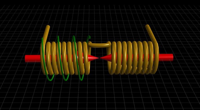
I spend a lot of time experimenting with small Coils:
As time goes on and more is learnt, one can very easily scale up and see what differences are:
Of course I have now gone even further in Scale now.
Anyway, I just wanted to share my Experiences for others, to help with progress and development.
Best Wishes,
Chris


Chris, good time!
The complex is expensive, the simple is also worth the money. The biggest problem that is overlooked is definition by action. I defined constructs like TRANSGENERATOR. Excitation - transformer, secondary circuit generator. This is not in a figurative sense, but in the literal sense and in action.
In a transformer, the primary and secondary circuits are wound around a core. Actions are mutual induction between wires, and their fields. The core there takes a secondary part, perhaps as a provocateur, for the current of the primary circuit.
In a generator, EMF arises from a magnetic field and has the definition of induction. The magnetic flux in the core of the transformer is located inside the core, that is, in the magnetic circuit.
To solve the problem, the secondary circuit must be placed inside the core. Fulfill the condition of current induction in the conductor from the magnetic flux.
This is just the most basic.
On the slide, the evolution of the mistake of researchers in understanding the design of the Figuera system
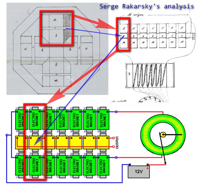
In Figer's generator design of 1902, the wave generator wire is laid in the gap between the poles of the electromagnets. Who decided that these are coils. Although it is likely that in the 1908 patent the activation of electromagnets is shown with a probable error. For the specialist it is visible, for the layman it is not.
Sincerely, Rakarsky!
Hello Rakarskiy,
Clemente Figuera was way before his time! I am always reminded of his words:
CLEMENTE FIGUERA
PRINCIPLE OF THE INVENTION - Watching closely what happens in a Dynamo in motion, is that the turns of the induced circuit approaches and moves away from the magnetic centers of the inductor magnet or electromagnets, and those turns, while spinning, go through sections of the magnetic field of different power, because, while this has its maximum attraction in the center of the core of each electromagnet, this action will weaken as the induced is separated from the center of the electromagnet, to increase again, when the induced is approaching the center of another electromagnet with opposite sign to the first one.
Because we all know that the effects that are manifested when a closed circuit approaches and moves away from a magnetic center are the same as when, this circuit being still and motionless, the magnetic field is increased and reduced in intensity; since any variation , occurring in the flow traversing a circuit is producing electrical induced current .It was considered the possibility of building a machine that would work, not in the principle of movement, as do the current dynamos, but using the principle of increase and decrease, this is the variation of the power of the magnetic field, or the electrical current which produces it.
The voltage from the total current of the current dynamos is the sum of partial induced currents born in each one of the turns of the induced. Therefore it matters little to these induced currents if they were obtained by the turning of the induced, or by the variation of the magnetic flux that runs through them; but in the first case, a greater source of mechanical work than obtained electricity is required, and in the second case, the force necessary to achieve the variation of flux is so insignificant that it can be derived without any inconvenience, from the one supplied by the machine. Until the present no machine based on this principle has been applied yet to the production of large electrical currents, and which among other advantages, has suppressed any necessity for motion and therefore the force needed to produce it.
Of course, we must accept, that a Technology, Electromagnetic Induction, that Humanity has had for almost 200 years, is incomplete. After all, it was Feynman and George I Cohn gave a great amount of detail to in the 60's. Well after Maxwell ( 1865 ) and well after Faraday ( 1831 ).
It is obvious that Clemente Figuera had completed what Science has still to complete, over 100 years ago! A feat we here at aboveunity.com have completed also and made Public Domain. 😉
Asymmetrical Electromagnetic Induction is not currently incorporated in Electromagnetic Induction, however: E.M.F = -N δΦB/δt is incomplete, still today. This Equation is entirely Symmetrical, it avoids and misses Asymmetry! Electromagnetic Induction can occur more than once in a Machine!
Best Wishes,
Chris
The Holcomb generator is a static generator the main characteristics
Notihing is moving
The rotor oft he solid state have no moving parts, iit is justa rotor form.
The rotor is not moving in the stator cavity.
It is the magnetic field that rotates, it is the magnetic poles that rotate.
There is no BEMF as in a standard electric motor.
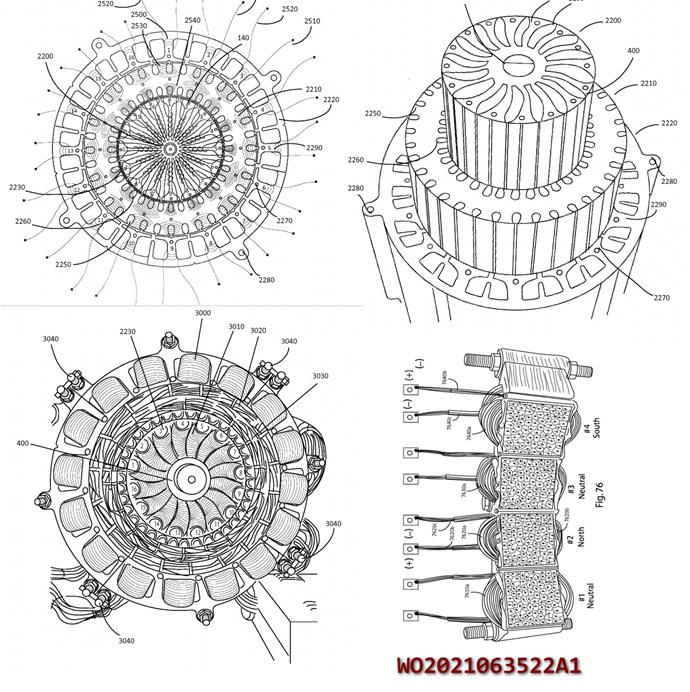
Very voluminous 2021 patent of 161 pages W02021063522A1
Jagau
Hey Jagau,
Yes it is, as it is described, however, this is an easy feat to show:
We have seen before, Holcomb is NOT the First, the Electric Motor used to Generate Electric Power:
_______________________________________________________
Not Loaded with Fan:Input:
12.80V * 0.722A = 9.2416 Watts
Output:
10.40V * 1.639A = 17.0456 Watts
COP: 17.0456 / 9.2416 = COP = 1.84
_______________________________________________________
Loaded with Fan:Input:
12.80V * 1.356A = 17.3568 Watts
Output:
10.40V * 1.633A = 16.9832 Watts
COP: 16.9832 / 17.3568 = COP = 0.98
_______________________________________________________
And, Tinman said:
Many here laugh at, and mok EMJ, but the fact is , he is basically right in what he is trying to put forward.
http://overunity.com/15395/partnered-output-coils-free-energy/msg460945/#msg460945
I have to say, not enough interested researches have paid attention. We are the only ones making any progress! While others are off trying to patent it 🤪
Perhaps one day, we will be recognised for our contributions?
Best Wishes,
Chris
My Friends,
Honestly, Holcomb's Description:
DECREASED DRAG ELECTRIC MACHINE WITH DUAL STATOR AND DISTRIBUTED HIGH FLUX DENSITY SLOT ROTOR PAIRS
FIELD OF THE INVENTION
The present invention relates generally to a decreased drag electric power generating machine, and more particularly, to reducing drag through the reduction of back electro-motive force (EMF) using a series of slot rotor pairs distributed around a dual wound stator.
BACKGROUND
Rapid consumption of exhaustible energy from the earth, largely in the form of fossil fuels and rapid depletion of associated energy resources and
accompanying environmental pollution and climate change drives the clear need for alternative energy supplies. Existing energy supplies must be used more efficiently.
In view of these and other issues, the need for sustainable power generation units is obvious. Renewable energy sources such as solar, wind, hydroelectric, electrostatic, temperature differential and geothermal energy have significant problems of availability, reliability and expense. Even gravity, if it could be efficiently harnessed, could provide a most attractive alternative.
One contribution to increasing consumption efficiency and sustainability is to increase the efficiency of electrical power generation. Increasing the conversion efficiency associated with converting mechanical energy to electrical power can provide potentially large gains. An ordinary electric generator typically converts close to 99% of supplied mechanical power into electric power based on a conventional 100% conversion efficiency comparison factor of one horsepower per 746 watts generated. Still further gains can be achieved using
superconducting technology. For example, a superconducting generator can be around 10-times smaller than a conventional generator for the same output.
While such gains are attractive, the expenses and challenges of implementing superconducting solutions are well known. It is therefore also desirable to achieve efficiency gains that are centered around more conventional structures. For example, if the reaction force or magnetic drag can be reduced or eliminated from the armature of an alternating current (AC) or direct current (DC) generator, the efficiency could be theoretically increased by 400 - 500%. Under such an increase in efficiency, one horsepower could generate up to 3,730 watts. Still further, by combining superconductivity with reduced magnetic drag, a greater than 10-fold increase in efficiency may be possible.
Every atom has a nucleus composed of positively charged protons and uncharged neutrons. Negatively charged electrons orbit the nucleus. In most atoms, the number of electrons is equal to the number of protons in the nucleus, so that there is no net charge. If the number of electrons is less than the number of protons, then the atom has a net positive charge. If the number of electrons is greater than the number of protons, then the atom has a net negative charge.
While on an aggregate scale, the universe is electrically neutral, local
concentrations of charge throughout biological and physical systems are responsible for all electrical activity. Further, not all electrons are involved in the structure of material. Vast numbers of electrons which are loosely bound
"electrons at large" are in equilibrium with outer shell electrons of atoms in the environment. It is from this pool of electrons in the atmosphere and in the ground, when set into combined motion along a path, that an electric current is generated. Thus if electrical pressure from a generator is applied to an electrical conductor, such as copper wire, and the circuit closed, electrons will flow along the wire from negative to positive, from atom to atom forming an electric current. The movement of energy associated with electrical current flow occurs at the speed of light, or approximately 186,000 miles per second.
For conceptual purposes, a wire connected to a DC power source will cause electrons to flow through the wire in a manner approximating water flowing through a pipe. The path of any one electron can be anywhere within the volume of the wire or even at the surface. When an AC voltage is applied across a wire it will cause electrons to vibrate back and forth in such a manner as to generate magnetic fields that push electrons toward the surface of the wire. As the frequency of the applied AC signal increases, the electrons are pushed farther away from the center and toward the surface.
An electric power generator contains two main parts: a stator and a rotor. The stator is generally made of iron or other ferro-magnetic material and contains long slots having a certain depth and in which wire coils are wound in such a fashion to allow electric power to be generated when magnetic fields emanating from the rotor move past the coils. The rotor contains a specific arrangement of magnets, which are generally wound armature electro-magnets whose strength is governed by the amount of current flowing in the armature windings. When the rotor spins inside the stator, the magnetic fields from the rotor induce a current in the stator windings thus generating what is referred to as electrical power.
The energy required to spin the rotor is typically supplied by a drive unit of some kind, such as an electrical drive motor, diesel or other fossil fuel motor, steam turbine or the like. At typical efficiencies, only 20% of the energy input by the driver motor is devoted to creating electric power. The remaining 80% is dissipated by magnetic drag, or braking forces, that develop between the rotor and the stator.
When current is supplied to a load from a conventional generator, a magnetic force or reaction force is created by the flow of the load current in the generator conductors that opposes the rotation of the generator armature. If the load current in the generator conductors increases, the drag associated with the reaction force increases. More force must be applied to the armature as the load increases to keep the armature from slowing. Increasing drag and increasing
load current leads to decreasing conversion efficiency and can eventually lead to destructive consequences for generator equipment.
It would be desirable for a way of increasing generator efficiency by reducing the motor reaction effect and the corresponding negative consequences.
SUMMARY
Various exemplary embodiments are discussed and described herein involving aspects of an electric machine, such as a generator that produces power with high efficiency and low drag.
In accordance with an aspect, a method is disclosed for reducing drag in an electric generator that includes distributing first members of slot rotor pairs along the outer periphery of a first stator section having induction windings accommodated in slots. Second members of the slot rotor pairs can be distributed along the outer periphery of a second stator section having induction windings accommodated in slots. The slots of the first stator section and the second stator section are axially aligned along a lengthwise and depthwise axis. The "outer" periphery of the second stator section can also correspond to an "inner circumference" where reference is made to a circular stator embodiment. The inner periphery of the first stator section and the inner periphery of the second stator section are adjacent to each other. The first members and the second members of the slot rotor pairs include slot rotors having at least one pair of wound armature pole sections of a first and a second magnetic polarity. The first and second members of the slot rotor pairs can be rotated in a synchronized manner such that a first one of the pole sections of the first member having the first magnetic polarity and a second one of the pole sections of the second member having the second magnetic polarity are aligned with the slots to provide maximum flux density in the induction windings to induce a current flow therein. The first member and the second member of the respective slot rotor pairs are aligned with the aligned slots of the first stator section and the second stator section along respective lengthwise axes of the first and second members and the slots such that the lengthwise axis of the first and second member are in normal alignment with the depthwise axis of the aligned slots.
The first and second members can be magnetically shielded such that flux generated by the first and second members is directed into the slots so as to minimize flux leakage and magnetic drag. The first members and the second members can be inserted into respective openings provided in the first and the second stator sections. The respective openings can be arranged in lengthwise alignment with the slots, to partially shield the first and the second members and can be provided with a longitudinal opening corresponding to a longitudinal opening of the slots in order to provide magnetic communication with the corresponding longitudinal opening in the slots and ultimately to the winding disposed therein.
The first and second members of the slot rotor pairs can be rotated about their axes in opposite directions over the slots such that the net torque generated by the polar force interaction between the first and second members is approximately zero. Accordingly, as the first one of the pole sections of the first member having the first magnetic polarity is rotated over a slot in a first direction, the second one of the pole sections of the second member can be sequenced such that it presents the second magnetic polarity opposite the first magnetic polarity in order to maximize the flux density in the aligned slots. The second one of the pole sections is being rotatable in a second direction opposite the first direction to form a magnetic circuit between the first and second magnetic polarities.
The first and second members can be driven in a synchronized manner that includes turning on an excitation current in an armature of the first one of the pole sections of the first member having the first magnetic polarity at an instant in time when the first one of the pole sections is positioned over a slot in a first direction. An excitation current in an armature of the second one of the pole sections of the second member having the second magnetic polarity can be similarly turned on. The first and second members can be shielded such that flux generated when an excitation current is supplied to the armatures of the first and the second members is directed substantially toward the slots. The induction windings can be connected in a three phase, high wye or three phase low wye connection.
In accordance with another exemplary aspect, an electromagnetic assembly for an electric generator can be provided that includes a dual stator having a first stator section and a second stator section. A first plurality of slots are arranged on an outer periphery of the first stator section and a second plurality of slots arranged on an outer periphery of the second stator section. Again, as noted hereinabove, with respect to a circular stator the outer periphery of the second stator section can refer to an "inner circumference." Respective inner peripheries of the first and second stator sections are disposed in adjacent relation and can include a back iron disposed therebetween to improve magnetic coupling through the slots. Each of the first and the second plurality of slots are aligned along a lengthwise and depthwise axis to form slot pairs, each of the plurality of slots having induction coil windings disposed therein.
The assembly can further include slot rotor pairs associated with the slot pair. Each of the slot rotor pairs has a first slot rotor member disposed in aligned relation with one of the first plurality of slots and a second slot rotor member disposed in aligned relation with one of the second plurality of slots corresponding to the slot pair. Each slot rotor member has at least a pair of magnetic poles with one of the pair of magnetic poles having a first magnetic polarity and another of the pair of magnetic poles having a second magnetic polarity. Each slot rotor member is capable of rotating about a longitudinal axis. The slot rotor pairs are disposed above the slot pairs such that the induction coil windings disposed in the slot pairs are exposed to magnetic flux generated by the slot rotor pairs. Each slot rotor member can be provided with a shield having an opening positioned over the slots to direct the flux into the slots but minimize external flux leakage. In addition, a shield section can be provided for shielding magnetic coupling of magnetic flux from the first and second slot rotor members and end teeth portions of the first stator section and the second stator section. The shielding can be made from mu metal. The first slot rotor member and the second slot rotor member are capable of rotating such that when magnetic flux of one of the magnetic poles of the first polarity associated with the first slot rotor member is directed to a corresponding first slot of the slot pair, magnetic flux of an associated one of the magnetic poles of the second polarity associated with the second slot rotor member is directed to a corresponding second slot of the slot pair such that the induction coil windings disposed in the first and second slots are exposed to increased magnetic flux and leakage of the magnetic flux is minimized. In one embodiment, the first plurality of slots can include 48 wire slots, and the second plurality of slots can include 48 wire slot. Each of the first stator section and the second stator section can have a substantially circular shape where the first stator section and the second stator section are concentric about a longitudinal axis of the dual stator. Alternatively, the first stator section and the second stator section are planar.
An excitation circuit can be provided that applies an excitation current to the first slot rotor member and the second slot rotor member so as to generate the magnetic flux when the one of the magnetic poles of the first polarity associated with the first slot rotor member is rotated into alignment with a corresponding first slot of the slot pair and to generate the magnetic flux when the associated one of the magnetic poles of the second polarity associated with the second slot rotor member is rotated into alignment with a corresponding second slot of the slot pair. The excitation circuit can further remove the excitation current from the first slot rotor member and the second slot rotor member in order to remove the magnetic flux at an instant when the one of the magnetic poles of the first polarity associated with the first slot rotor member is rotated out of alignment with the corresponding first slot of the slot pair, and to remove the magnetic flux at an instant when the associated one of the magnetic poles of the second polarity
associated with the second slot rotor member is rotated out of alignment with the corresponding second slot of the slot pair. A diode circuit can be provided for transmitting a current generated when the magnetic flux is removed from the first and the second slot rotor members to a battery. The excitation circuit can include a commutator circuit associated with the first and second slot rotor members, the commutator circuit selectively coupling ones of the first and second slot rotor members to the excitation current as the ones are rotated into alignment.
It is an object therefore to provide distributed slot rotor pairs that rotate in close proximity to aligned wire slots disposed around the circumferences of a dual stator of an electric power generator,
It is a further object to demonstrate to complete an intensified magnetic circuit and place maximum moving flux into the wire slots using slot rotor pairs.
It is a further object to release energy, which would be consumed by drag, as electric power by driving a high efficiency distributed slot rotor generator.
BRIEF DESCRIPTION OF THE DRAWINGS
In order that embodiments of the invention may be fully and more clearly understood by way of non-limitative examples, the following description is taken in conjunction with the accompanying drawings in which like reference numerals designate similar or corresponding elements, regions and portions, and in which:
FIG. 1 is a diagram illustrating an exemplary wound dual stator machine having dual electromagnetic slot rotors inserted into shielded recesses in accordance with an embodiment;
FIG. 2 - FIG. 49 are diagrams successively illustrating a series of 7.5 ° clockwise rotational advancements of an exemplary configuration with 48 outer stator slots having corresponding four-pole electromagnetic slot rotors in accordance with an embodiment;
FIG. 50 is a diagram illustrating an exemplary three-phase "high wye" winding connection embodiment of the dual stator arrangement of FIG. 1;
FIG. 51 is a diagram illustrating an exemplary sequential phase coil lead arrangement in a three-phase, counterclockwise lap wound stator embodiment;
FIG. 52 is a diagram illustrating the wound stator arrangement of FIG. 51 and an exemplary three-phase "high wye" winding connection for the four-pole electromagnetic slot rotors in accordance with an embodiment;
FIG. 53 is a diagram illustrating an exemplary sequential phase coil lead arrangement in a three-phase, clockwise lap wound stator embodiment;
FIG. 54 is a diagram illustrating one of an exemplary four-pole electromagnetic slot rotor and related shielding arrangements;
FIG. 55 is a superior lateral projection diagram illustrating an exemplary four-pole electromagnetic slot rotor;
FIG. 56 is a diagram illustrating a pair of exemplary four-pole electromagnetic slot rotors associated with a dual stator machine;
FIG. 57 is a diagram illustrating a dipole embodiment of an exemplary
electromagnetic slot rotor including pole windings and laminated mu metal shielding;
FIG. 58 is a diagram further illustrating a dipole embodiment of an exemplary electromagnetic slot rotor including pole windings, an exemplary cog wheel drive and mu metal shielding;
FIG. 59 is a diagram illustrating a superior lateral projection of a dipole embodiment of an exemplary electromagnetic slot rotor;
FIG. 60 is a diagram illustrating a superior lateral projection of an exemplary steel sleeve shield containment means and mu metal magnetic shielding means;
FIG. 61 is a diagram illustrating a dual pole embodiment of an exemplary dipole electromagnetic slot rotor including pole windings, mu metal shielding around the rotors and on the stator and further illustrating a wire slot flux pattern between the north pole and the south pole; and
FIG. 62 is a diagram illustrating a pattern of separate phases of three phase power as it proceeds through one cycle of 360 electrical degrees as is generated by an exemplary generator.
DETAILED DESCRIPTION
In accordance with various exemplary embodiments discussed and described herein, motor reaction force may be reduced and other problems can be solved in an embodiment whereby a series of rotatable bipolar or quadrapolar electromagnets, electrical armatures, rotors or the like, can be disposed or otherwise inserted on their axis into recesses in a stator. The recesses can be shielded and positioned over each wire slot of the generator such that wire slots are covered in the correct pattern to mimic a central single 4 pole rotor of a conventional generator. Maximum flux density is obtained in accordance with a novel embodiment whereby wire slots on an inner stator circumference and an outer stator circumference are each provided with slot rotors forming an exemplary dual slot rotor, dual stator configuration.
The following detailed description provides an understanding of embodiments of the invention as illustrated and described herein below. Exemplary embodiments are provided that allow electric energy to be generated based on directly or indirectly on conventional fossil fuel driven energy sources with greatly increased efficiency resulting in reduced consumption of fossil fuel supplies and reduced output of greenhouse gases. Accordingly a high efficiency generator is provided that shields or separates the drag creating magnetic forces from one another so that upwards of 80% of the driving energy which conventionally is consumed by magnetic drag is converted to electric power.
In accordance with an embodiment as will be described in greater detail in connection with the illustrations below, the classic rotor armature and stator have been replaced by a laminated steel dual stator having a stator section with an outer circumference and a stator section with an inner circumference. Each stator section has, in one example, 48 wire slots that are magnetically coupled with individual slot rotors of corresponding slot rotor pairs. The corresponding slots from the inner and outer stator sections are aligned with each other and a ferrous back iron can be disposed between the stator sections to increase the flux coupling. A slot rotor and/or slot rotor transmission support means can also be attached to the stator. The support means can be oriented in a variety of manners such as, for example, in a manner whereby the plane of the support means base is parallel with the planes of the end portions of the stator. A slot rotor pair support means, including, for example, bearing blocks and the like can also be attached to the base support means.
The slot rotor pair support means can support the combined 96 slot rotors of the inner and outer stator section circumferences. The slot rotors can be constituted of, for example, two pole or four pole wound armature poles and associated bearing mechanisms and other mechanisms. As will be appreciated, the exemplary apparatus can be configured with 48 slot rotor assemblies for the outer circumference and 48 slot rotor assemblies on the inner circumference. The slot rotors are positioned in close proximity to the wire slots in order for each rotor of the slot rotor pair to form a closed magnetic circuit through both slots. It should be noted that one of the slot rotors in the slot rotor pair rotates clockwise and the other rotates counterclockwise in order for the proper magnetic flux to be delivered to the wire slots.
The exemplary 96 armature mechanisms can be contained in magnetically shielded cylinders such as mu metal cylinders with an appropriate open slot in the shield that is positioned directly over the stator wire slots. Each slot rotor armature of the slot rotor pair can be energized and the individual rotor assembly can be rotated to provide alternating fields of north and south pole magnetic flux field energy into the open wire slots of the induction coils in the stator. Each of the slot rotors in the slot rotor pair is rotated such that a pole of one slot rotor makes up a complete magnetic flux circuit with the corresponding opposite pole of the other slot rotor of the slot rotor pair thereby directing a maximum amount of magnetic flux into the slots. The magnetic poles are activated with DC current via a brush and commutator apparatus or other appropriate solid state
mechanism such that the magnetic pole is activated only as it passes over the wire slot. Since the opening of the mu metal laminated shield is precisely
positioned over the wire slot, the slots of the stator are exposed to only a small but intense window of magnetic flux. Accordingly, only minimal electromagnetic drag upon the slot rotors is experienced.
In accordance with an aspect, the slots in the outer circumference and inner circumference are aligned. The magnetic poles of each individual member of the pair of slot rotors rotate in a coordinated fashion respectively over the inner and outer aligned slots such that, for example, as a north pole of one of the pair of rotors rotates over one slot of the inner slot, a south pole of the other of the pair of rotors rotates over the outer slot. Thus, the dual rotors can be sequenced such that they present opposite poles to corresponding slots in the inner and outer stators respectively thereby making up a magnetic circuit between the north pole and south pole as they rotate past one another. The resulting magnetic circuit generates a very high flux density into the slots on both the inner and outer stators and into the shared back iron.
In an exemplary bipolar slot rotor, one of the two pole sections is north pole charged and the opposite section is south pole charged. In one embodiment, the north pole section can be constituted by a 120° section and the south pole can be constituted by an opposite 120° section with a 60° neutral zone between poles on each side thereof. Pole sections can be shielded with mu metal shielding. Each of the slot rotor arrangements can be contained in a longitudinal cylindrical cavity that is located in close proximity to and extends lengthwise along the opening of the winding slots. The slot rotor mechanism, including a mu metal shield can be contained within a steel cylinder or partial cylinder which has an opening that approximately corresponds and is in communication with the opening of the stator wire slot. An opening along the length of the steel cylinder can be in alignment with a slot or opening along the length of the mu metal shield to allow magnetic coupling between the slot rotor and the winding slot. Due to the mu metal insulation, the north slot rotor pole of one of the pair of slot rotors only sees a narrow segment of the opposing field from the south slot rotor pole of the other of the pair of slot rotors coming through the wire in the wire slots. The degree of magnetic interaction between the slot rotor pairs and flux coupling from the opposite magnetic poles through the back iron is minimal due to current flow within the windings that occupy the slots. It should be noted that the induction coils of the stator are arranged in four groups per phase, four coils per group and three phases. The north poles and south poles of the slot rotors rotate in sequence and thereby mimic the four poles of a standard four pole, three phase generator.
It will be appreciated that in an embodiment, the slot rotors may be fashioned, for example, as wound electromagnetic armatures that are positioned as 48 pairs of rotors around the circumference of a dual wound stator. While 48 pairs are shown for illustrative purposes, it is by way of example only and different numbers of slot rotor pairs can be used. An individual slot rotor armature may be made by fashioning a series of laminated steel pole pieces upon a shaft in a manner similar to that of a conventional generator armature. The completed pole pieces can be wound in a conventional manner with insulated wire to suitable winding specifications for the operating demands of the generator. Power can be applied to the armatures as will be described in greater detail hereinafter.
To drive the shafts of the slot rotor mechanisms, a gear mechanism can be provided on one end of the individual slot rotor shafts which meshes with a gear mechanism on the same end of a magnet containment means over the circumference of the stator. As the slot rotor pairs and their respective armatures are rotated on both sides of the stator in a synchronized manner by the gear mechanism, power can be generated with greatly reduced drag as compared with a single, central rotating armature of a conventional generator.
Power generation in accordance with the reduced electromagnetic drag provided by various embodiments discussed and described herein can result in, for example, a four to five fold increase in electrical energy output with the same mechanical or kinetic energy input. With an exemplary mechanical input of, for instance, one horsepower provided by an electric drive motor driving the
exemplary gear mechanism, one horsepower of mechanical energy may generate approximately 3,000 watts, rather than the more conventional limit of 746 watts. Therefore, as the conventional 1 horsepower electric motor drives the gear mechanism the generator of the invention will consume 746 watts of electric energy and generate 3,000 watts, thereby generating an additional 2,254 watts of usable energy.
In an embodiment, a series of bipolar or quadrapolar magnetic slot rotors can be enclosed inside a cylinder, such as a shielded cylinder or the like, which can be fitted into, for example, cylindrical shaped opening provided in the stator. A small cylinder housed in a larger cylinder insert can be pressed into a bearing holder of each rotor which is positioned over aligned wire slots on the peripheries of sections of the stator of the generator such that only the area over the wire slots is exposed to the magnetic field of the spinning slot rotors, which can extend along the length of the wire slot. A North magnetic pole of one of the slot rotors in the pair and the South magnetic pole of the corresponding one of the slot rotors in the pair complete a magnetic circuit through the wire slots thereby exposing the wires in the slots to maximum moving lines of flux.
The slot rotors can be rotated in a synchronized fashion by a transmission mechanism that is, in turn rotated by, for example, a shaft off one of the cogs in the transmission, which can be attached to a mechanical drive. The foregoing arrangement, by preventing unwanted magnetic interaction between the stator and the armature, will decrease drag and, as an electrical load is applied to the generator, magnetic flux density and corresponding current flow increases in the wire slots.
The process of electrical power generation can be thought of as a process by which the input of kinetic energy, for example, is used to move a magnetic field. The resulting moving magnetic field moves across the conductor wires in the stator induction wire slots of the electric generator causes an electrical current to flow in the coils of the generator. The electrical current flowing in the stator coils creates a magnetic field by virtue of the physical construction of the coils and the laminated steel in which they are wound. The newly created magnetic field in the stator iron increases in strength as electric power is increasingly drawn from the generator and is approximately equal and of opposite polarity to the original source of the magnetic field. The stator field interacts with the original source of the magnetic field in the rotor which ends up dissipating the kinetic energy input to the system. Therefore, it may appear that kinetic energy is being converted into electrical energy. In fact the kinetic energy is only eliciting electrical energy which, by virtue of design of the generator, is dissipating the kinetic energy by acting in the opposite direction of the original kinetic energy.
The problem associated with such energy dissipation is a fundamental problem of generator design rather than a practical necessity of the generator process. A change in generator design can eliminate the unwanted byproduct of back electromotive force (EMF) and subsequent magnetomotive force without affecting the generating process. The input of kinetic energy is no longer related to electrical output. In accordance with various embodiments, an electrical generator system can be provided in which a conventional magnetically polarized generator rotor is replaced by a series of distributed slot rotors having magnetic poles affixed over and in close proximity to each wire slot. In order to isolate the magnetic flux and direct it to the slots, the slot rotors can be shielded with, for example, mu metal, which can be an annealed metal of 75% nickel, 15% iron, plus copper and molybdenum.
A stator in accordance with the embodiments discussed and described herein can contain wire slots on the inner circumference as well as the outer
circumference. It should be noted however that, by use of the terms "inner" and "outer," illustrative reference is made to a circular shaped stator embodiment. It will be appreciated and should be emphasized that the dual stator need not be circular and can be linear or planar, or can be of a semi-circular or other shape and have dual stator sections with the same effect as the embodiments specifically illustrated and described herein. In such an embodiment where the
stator is not circular, the terms inner circumference and outer circumference can be replaced by terms such as first outer periphery and second outer periphery. Further, since an exemplary stator in various embodiments is described herein as dual stator arrangement, the first outer periphery and second outer periphery can include the stator surface containing the slot rotors. The respective inner peripheries of the stator sections can be adjacent to and can face each other either directly or with an intervening member such as a back iron or the like.
The slots in the outer circumference and inner circumference are aligned. The magnetic poles rotate over both aligned slots such that as a north pole rotates over one slot, the pole over the aligned slot is sequenced such that it presents a south pole rotating in the opposite direction thereby making up a magnetic circuit between the north pole and south pole as they rotate past one another. This magnetic circuit generates a very high flux density into the slots on both the inner and outer radius and into the shared back iron. Each of the magnetic bodies is constructed as small, wound inductive magnetic armatures. The unique design is powered by a DC current supply which activates pole coils through a brush and slip ring mechanism such that the magnetic poles are only activated as they are rotated over the unshielded wire slot. The small armature mechanism is separated from the back EMF (and related magnetomotive force) by mu metal shields placed on the flat portion of the stator tooth between each slot which shields all except for an open slot over the wire slots of the stator. In addition, mu metal shield cylinders completely surround the electromagnetic armature mechanisms. These cylinders are only open to the wire slots of the stator. The shielded electromagnetic poles are rotated by a transmission mechanism which effectively exposes the wire slots to a high density moving magnetic field over and through the slots of the induction coils of the stator. The magnetic poles of the armature mechanism are only activated as they rotate over the wire slots. With the proper stator winding and pole activation sequence, clean balanced 3 phase alternating current (AC) can be generated. By making the appropriate changes, single phase, 2 phase and direct current may be generated. The
attributes of the current invention allows generators of practically unlimited size with greatly improved efficiency to be constructed. The efficiency increase when compared to a present day electrical generation technology is significant.
With reference now to the figures, FIG. 1 shows an end view of an exemplary embodiment involving a dual laminated steel stator 1 embodiment with 96 armature mechanisms, or slot rotors as described hereinafter, which form 48 slot rotor pairs. The slot rotor pairs, such as is exemplified by outer slot rotor 2 and inner slot rotor 10, are shown positioned over wire slots 30 of the outer stator race and wire slots 116 of the inner stator race of stator 1. In the present embodiment, the outer race slots of laminated steel stator 1 contains a series of 48 slots, which slots and relationship between slot rotors can be more readily appreciated with reference to FIG. 2. For illustration purposes, FIG. 2 through FIG. 49 show only an exemplary outer stator race. However it will be
appreciated that since the inner stator race (not shown) is concentrically positioned and since the inner and outer slots are aligned, the same rotational advancement, such as in 7.5 degree increments from figure to figure is applicable. However, as previously noted, the slot rotors of the inner
circumference will rotate in an opposite direction and have slot rotor poles of the opposite polarity being positioned over the slots as compared to those of the outer slot rotors.
It will further be appreciated that, with reference to FIG. 1 , the outer race slots contain induction coils associated with a 3 phase generator. In the figure, the first phase 12, the second phase 14 and third phase 13. The various phase coils can be connected using a wye connection such as a "low wye" or a "high wye" connection. The inner race slots can also contain induction coils of a 3 phase generator wherein the first phase 15, the second phase 17 and the third phase 16 which can also use a wye connection such as a low wye or high wye. The rotating north-south-north-south pole energy is separated by areas of magnetic void between each pole as is represented in FIG 1 . In an embodiment, the four-pole electromagnetic slot rotors 2 in the outer race and electromagnetic slot
rotors 10 in the inner race are only turned on, energized or excited as they rotate past the wire slots the depiction represents activation by outlined magnetic poles.
While, as noted, FIG. 1 depicts an exemplary stator 1 with both outer race wire slots 30 and inner race wire slots 116, FIG. 2 - FIG. 53 depict examples where only the outer wire slots 30 are shown. For the sake of simplicity, FIG. 2 - FIG. 49 depict the pole sequencing with reference only the outer slot 30 for the complete 360° rotational cycle. FIG. 50 - 53 illustrate winding connections and the like, with reference only to the outer slots 30 for simplicity.
To better understand the exemplary dual stator and slot rotor pair structure and operation, a description is provided that encompasses each magnetic section of the stator and the slot rotors during an instant of rotation. The term covered as used herein below refers to various states whereby a particular slot rotor pole is in full or partial alignment with the underlying wire slot as it rotates by the slot. Each slot is shown with a corresponding slot number shown inside the slot in brackets such as [1] through [48]. With reference again to FIG. 1, as can be seen, slot [45] is covered by a north pole which can be energized or otherwise activated as is represented by a solid state of the pole coloring nearest the slot. Progressing counterclockwise, slot [46] is covered by an activated magnetic pole as is slot [47], [48], [1], [2], [3], and [4]. An indication that all eight wire slots are receiving magnetic flux from the activated slot rotor is provided by the solid state of the pole coloring. The arc 18 refers to the span of north pole #1. Continuing counterclockwise on FIG. 1 , the rotors 4 covering slots [5], [6], [7], [8] are not excited and therefore are not emitting any magnetic flux as is indicated by the outlined or uncolored state of the pole coloring.
Next, excitation for south pole #1 begins. The slot rotors that cover slots [9], [10], [11], [12], [13], [14], [15] and [16] are excited as is indicated by the solid state of the pole coloring. The arc 19 refers to the span of south pole #1. Continuing counterclockwise, the slot rotors that cover slots [17], [18], [19] and [20] are not excited and therefore are not emitting any magnetic flux as is indicated by the
outlined state of the pole covering. Next, excitation for north pole #2 begins. The rotors that cover slots [21], [22], [23], [24], [25], [26], [27], and [28] are excited as is indicated by the solid state of the pole covering. The arc 20 refers to the span of north pole #2. Continuing counterclockwise in FIG 1 , the rotors covering slots [29], [30], [31] and [32] are not excited and therefore are not emitting any magnetic flux as is indicated by the outlined state of the pole coloring. Next, excitation for south pole #2 begins. The rotors which cover slots [33], [34], [35], [36], [37], [38], [39] and [40] are excited as is indicated by the solid state of the pole coloring. The arc 21 refers to the span of south pole #2. Continuing counterclockwise in FIG 1 , the rotors covering slots [41], [42], [43] and [44] are not electrically excited and therefore are not emitting any magnetic flux as is indicated by the outlined state of pole coloring.
When the pole rotors 3 and 9 begin to rotate in a synchronous fashion, four spans of actively excited slot rotors and corresponding magnetic poles distributed around the outer and inner circumferences of the stator each occupy
approximately 60° of the total stator circumference. The active spans are interspaced with four magnetically void segments corresponding to the slot rotors that are not actively excited that each occupy approximately 30° of the rotor circumference. FIG. 2 through FIG. 49 are sequential drawings in which the armatures of the slot rotors are rotated 7.5° in a clockwise fashion from those of the previous figure. With reference to FIG. 1 , the outer race wire slots and slot pole rotors are identical to those of FIG 2 - 49. FIG. 1 additionally shows the inner race wire slots and corresponding slot pole rotors of the slot rotor pairs associated with the dual stator, dual slot rotor configuration of various inventive embodiments. It should also be noted that in accordance with the embodiments, the dual slot rotors rotate in opposite directions such that the poles rotating over the inner slots 116 and the outer slots 30 are synchronized. When the poles are in position, they can be turned on simultaneously such that the north pole flux lines from one are synchronized with the south pole flux lines from the other and a magnetic circuit is completed therebetween. The resulting magnetic flux
excites the stator induction coils while experiencing very little resistance due to counter EMF produced as the magnetic arc traverses the circumference of the stator. The rotational torque of the slot rotors approximates that of the separation forces in a mechanical gear system. Torque increase associated with the generation portion of the slot rotor's rotational cycle is only a small fraction of the force required to move these two poles laterally past one another due to the attracting and repelling flux lines of the lateral movement. As the trailing edge of the magnetic field produced by the rotating slot rotor pairs reaches the edge of the shielding slot and the wire slot, the DC excitation current for the rotor armatures is turned off until the next generation cycle.
It will be appreciated that in order to control the application of the current to the various slot rotor armatures, various means can be used both to synchronize rotation and energize the slot rotor armatures. For example, commutator arrangements can be used to selectively apply current to the slot rotor armatures at the appropriate time as the slot rotors are synchronously rotated about their respective axes. Alternatively, the application of current can be controlled by a computer, processor, controller or other suitable logic as would be appreciate to control the application of current to the slot rotor armatures and to accomplish current control for output voltage regulation purposes. Such a controller can make corrections at a rate much higher than the rotational rate of the slot rotors and thus can apply a degree of high resolution control that would be more difficult with a commutator arrangement. Also including in any such a rotation and excitation control circuit is a current recover circuit. As the current in the slot rotors is turned off, the excitation field in the rotor collapses sending a pulse of current in the opposite direction, which is returned to a battery through a diode circuit such that a minimal amount of power is consumed by the excitation of the slot rotors.
In accordance with various exemplary embodiments, and, in particular, a 48 slot embodiment, all of the slot rotors in the outer race and inner race of the stator can be connected in a permanent positional relationship through a transmission
which is driven by a driver motor or other driving element. The synchronous rotation of the outer race slot rotors and the inner race slot rotors allows the generation of an arc of induction flux across the aligned wire slots in the outer race and in the inner race. The synchronization is such that at any one instant, 8 slot rotor pairs generate an arc of north pole flux in 8 corresponding slots of the outer race and an arc of south pole flux in 8 aligned slots in the inner race. The physical makeup of the slot rotors and the induction coils in the outer race and the inner race are identical. However, it will be noted that that rotational relationship of the inner slot rotors to the inner race slots is offset by 90° as compared to the rotational relationship of the outer slot rotors to the outer race slots.
With further reference to an embodiment, for example, as depicted in FIG. 1, it is noted that the 3 phase induction coils of the outer race are wound in the same fashion as the 3 phase induction coils of the inner race slots, however north pole #1 (22) is rotated 90° counterclockwise when compared to the north pole #1 (I8) of the outer race. It will further be noted an exemplary mu metal magnetic shield 8 is shown, for illustrative purposes, as being placed over the inner race slot rotor of slot #4, as is the shielding 6 over the outer race slot rotor of slot #4. Further examples are provided of mu metal magnetic shielding 5 on a stator tooth of the outer race and shielding 7 is on a stator tooth on the inner race. In accordance with an embodiment, though not shown, the shielding will be placed over each of the 96 rotors and over all the stator teeth of both the inner race and outer race to minimize flux leakage between the rotors and the stator sections.
As previously noted, an exemplary generator can be configured for three-phase, two-phase, single phase and DC generation. In the present example, a three-phase implementation is shown. Accordingly, a depiction of the internal wiring connections of the 3 phase 4 pole 12 coil generator is shown in FIG. 50 for both the outer race windings and the inner race windings. As would be readily appreciated by one of skill, the illustrated hookup is referred to as a "high wye" connection. More specifically, in a high wye connection, each phase can be
configured to include two winding circuits which may be connected in series and produces 480 volts. Alternatively, the two of the winding circuits may be connected in parallel and can be referred to as a "low wye" connection. While a low wye configuration produces 240 volts, the current output can be doubled as compared with the "high wye" such that the power output is the same for each hookup.
Following the phase circuits from the power output leads through the circuits to the neutral "wye" connection for the outer race windings and the inner race windings, and with initial reference to the outer race, phase A leg 33 includes coil group 38 wound in a counterclockwise or north pole (N) direction. Input is at circle 1 ( © ) and output is at circle 4. The output lead 69 connects with coil group 41 , wound in a clockwise or south pole (S) direction with an input at circle 1 and output at circle 4. The output lead 72 connect with coil group 44, wound in a counter clockwise (N) direction with an input at circle 7 and output at circle 10. The output lead 75 connects with coil group 47 wound in a clockwise (S) direction with input at circle 7 and output at circle 10. The output lead 78 connects with lead 66 at the central "wye" connection 62 with the other two phases.
Phase B leg 35 includes coil 40 wound in a counterclockwise (N) direction with an input at circle 2 and an output at circle 5. The output lead 71 connects with coil group 43 which is wound in a clockwise direction (S) with an input on circle 2 and out on circle 5. The output lead 74 connects to coil group 46 wound in a counterclockwise (N) direction with an input at circle 8 and an output at circle 1 1. The output lead 77 connects to coil group 49 which is wound in a clockwise (S) direction with an input at circle 8 and an output at circle 1 1. The output lead 80 connects with lead 67 making up a portion of the "wye" connection at 62.
Phase C leg 35 connects to coil group 42 wound in a counterclockwise (N) direction with an input at circle 3 and an output at circle 6. The output lead 73 connects to coil group 45 wound in a clockwise (S) direction with an input at
circle 3 and an output at circle 6. The output lead 76 connects to coil group 48 wound in a counterclockwise (N) direction with an input at circle 9 and an output at circle 12. The output lead 79 connects to coil group 39 wound in a clockwise (S) direction with an input at circle 9 and an output at circle 12. The output lead 70 connects to conductor 68 which forms the third leg of the "wye" connection 62.
With reference now to the inner race windings, phase A2 leg 34 connects to coil group 50 wound counterclockwise (N) direction with an input at circle 1 and an output at circle 4. The output lead 81 connects to coil group 53 wound in the clockwise (S) direction with an input at circle 1 and an output at circle 4. The output lead 84 of the two coil groups connects to coil group 56 wound in the counterclockwise (N) direction with an input at circle 7 and an output at circle 10. The output lead 87 connects to coil group 59 wound in a clockwise (S) direction with an input at circle 7 and an output at circle 10. The output lead 90 connects to conductor 63 which connects with the "wye" connection 62 with the other two phases.
Phase B2 leg 36 connects with coil group 52 wound in a counterclockwise (N) direction with an input at circle 2 and an output at circle 5. The output lead 83 connects to coil group 55 wound in a clockwise (S) direction with an input at circle 2 and an output at circle 5. The output lead 86 connects to coil group 58 wound in a counterclockwise (N) direction with an input at circle 8 and an output at circle 11. The output lead 89 connects to coil group 61 wound in a clockwise (S) direction with an input at circle 8 and an output at circle 11. The output lead 90a connects to neutral lead 64 which connects to the "wye" connection 62.
Phase C leg 38 connects with coil group 54 wound in a counterclockwise (N) direction with an input at circle 3 and an output at circle 6. The output lead 85 connects to coil group 57 wound in a clockwise (S) direction with an input at circle 3 and an output at circle 6. The output lead 88 connects to coil group 60 wound in a counterclockwise (N) direction with an input at circle 9 and an output at circle 12. The output lead 91 connects to coil group 51 wound in a clockwise (S) direction with an input at circle 9 and an output at circle 12. The out lead 82 connects to conductor 65 which forms the third leg of the "wye" connection 62.
With the above described spacing of the inner race windings and the outer race windings and the internal connections, three phase power can be generated with the phase legs separated electrically by 120°, when an exemplary four pole rotating magnetic field with 60° of coverage of the stator with each pole and a 30° segment of no magnetic field between each 60° pole is employed and rotated at the proper speed from the dual slot rotors of the described embodiments.
With reference to FIG. 51 , a depiction of the actual coil groups which are represented diagrammatically in FIG. 50 is shown. The input and output wires for each wound coil group in FIG. 51 correspond to the same numbers as represented in FIG. 50. The correspondence can be described as follows: Phase A coil group #1 input wire #1-92, output wire #2-93; Phase C coil group #1 input wire #3-115, output wire #4-94; Phase B coil group #1 input wire #5-95, output wire #6-96; Phase A coil group #2 input wire #7-97, output wire #8-98; Phase C coil group #2 input wire #9-99, output wire #10-100; Phase B coil group #2 input wire #11-101 , output wire #12-102; Phase A coil group #3 input wire #13-103; output wire #14-104; Phase C coil group #3 input wire #15-105, output wire #16-106; Phase B coil group #3 input wire #17-107, output wire #18-108; Phase A coil group #4 input wire #19-109, output wire #20-110; Phase C coil! group #4 input wire #21-111 ; output wire #22-112; Phase B coil group #4 input wire #23-113, output wire #24-114.
It will be appreciated that the above detailed description provides the ability to easily transpose the internal hookup diagram shown in FIG. 50 to an actual exemplary wire hookup of wound three phase coils of an embodiment. The winding depicted in FIG. 52, as in FIG. 50, is a three phase four pole winding. There are four coil groups per phase and are counterclockwise lap wound. The
numerical labeling exercise in FIG. 50 and FIG. 51 denote like elements except for the coil numbers which denote like elements with FIG. 50.
With reference to FIG. 52, Phase A leg 92 is connected to coil group 38-A wound in a counterclockwise (N) direction with an input at circle 1 and an output at circle 4. The output lead 93 connects to coil group 41 -A which is wound in a clockwise (S) direction with an input at circle 1 and an output at circle 4. The output lead of these two coil groups 97 connects to coil group 44-A wound in a
counterclockwise (N) direction with an input at circle 7 and an output at circle 10. The output lead 104 connects to coil group 47-A wound in a clockwise (S) direction with an input at circle 7 and an output at circle 10. The output lead 109 makes up in the "wye" connection 62 with the other two phases.
Phase B leg 95 connects with coil group 40-B wound in a counterclockwise (N) direction with an input at circle 2 and an output at circle 5. The output lead 96 connects to coil group 43-B wound in clockwise (S) direction with an input at circle 2 and an output at circle 5. The output lead 101 connects to coil group 46-B wound in a counterclockwise (N) direction with an input at circle 8 and an output at circle 11. The output lead 108 connects to coil group 49-B wound in a clockwise (S) direction with an input at circle 8 and an output at circle 11. The output lead 113 connects to a portion of the "wye" connection 62.
Phase C leg 99 connects to coil group 42-C wound in a counterclockwise (N) direction with an input at circle 3 and an output at circle 6. The output lead 100 connects to coil group 45-C wound in a clockwise (S) direction with an input at circle 3 and an output at circle 6. The output lead 105 connects to coil group 48-C wound in a counterclockwise (N) direction with an input at circle 9 and an output at circle 12. The output lead 112 connects to coil group 39-C wound in a clockwise (S) direction with an input at circle 9 and an output at circle 12. The output lead 115 connects to "wye" connection 62.
FIG. 53 illustrates an internal race winding of the stator 117 of the invention with a three phase four pole clockwise lap winding with four coils per phase. The
slots 116 contain slot insulation as well as insulation between the phase coils. Phase A coils 120 are depicted in blue, Phase C coils 119 are depicted in brown, and Phase B coils are depicted in red.
FIG. 54 illustrates a four pole electromagnetic slot rotor including a portion of the stator, the winding slot, and the windings and shielding. Stator slot 116 reveals a cross-section of the copper induction coils making up the windings. The stator slot can be insulated with a material of high dielectric characteristics. The slot wedge 127 holds the wire firmly in the slots. The stator surface 125 is covered over the stator tooth with magnetic shielding 117. The four pole rotor 128 consists of laminated poles wound with copper magnet wire. North pole 126 is wound in a counterclockwise fashion, south pole 124 is wound in a clockwise fashion, north pole 121 is wound in a counterclockwise fashion, and south pole 19 is wound in a clockwise fashion. Shaft 122 is supported by bearings in a bearing pocket inside a support means. There is a center hole 120 in the shaft such that power wires may be fed to the electromagnetic pole heads. The electromagnetic shield 123 shields any interaction of magnetic fields when the electromagnetic heads are turned off just as they pass the slot opening 1 7. As described hereinabove, when the DC current is turned off the magnetic field collapses and reverses the polarity for an instant causing a current spike that can be recovered for storage in a battery or the like.
FIG. 55 further illustrates an exemplary four pole rotor 128 of an embodiment including shaft 122, lateral views of a magnetic pole shoe face 132 and 133. South pole 124 is wound in a clockwise fashion, north pole 121 is wound in a counterclockwise fashion, south pole 119 is wound in a clockwise fashion, and north pole 126 is wound in a counterclockwise fashion.
FIG. 56 further illustrates an exemplary pole rotor configuration providing distinct advantages. In accordance with an embodiment, the inner race slot and the corresponding outer race slot with their accompanying slot rotors are aligned with the slot rotors rotating in opposite directions. Accordingly, when a north pole rotates over the wire slot of the outer race, the opposite pole rotates in a synchronous fashion over the inner race wire slot. The described arrangement allows the completion of a magnetic circuit between the north poles of ones of the pairs of slot rotors and south poles of the others of the pairs of slot rotors as they rotate over the slots in a 60° arc. The combined action of the aligned fields of the slot rotors carries a high density magnetic flux across the induction coils in each slot of the stator. Moreover, the geometry and shielding directs the vast majority of the moving flux into the paired wire slots of the outer and inner stator races.
Close examination of FIG. 56 reveals the outer race wire slot 134, the inner race wire slot 116 and the corresponding outer four pole slot rotor pole 144, and the inner four pole slot rotor pole 124. The slot rotors and slots are positioned such that the rotor is in close proximity to the stator wire slot. The four pole rotors 128 are rotated about shafts 120 and 140 which sit in bearings which are in turn contained in bearing pockets. The shaft 140, for example, contains a center hole 138 which contains the electrical conductor for the pole coils. North pole 144 is wound in a counterclockwise fashion, south pole 142 is wound in a clockwise fashion, north pole 139 is wound in a counterclockwise fashion, and south pole 137 is wound in a clockwise fashion. The magnetic shield 141 surrounds the rotor. A stator magnetic shield 143 is placed on the stator tooth. The inner race wire slot 116 and four pole rotor 128 is positioned such that the rotor is in close proximity to the stator wire slot. The four pole rotor is supported by shaft 122 which sits in bearings which are in turn contained in bearing pockets and support means. The shaft 122 contains a center hole 120 which contains electrical conduits for the pole coils. South pole 124 is wound in a clockwise fashion, north pole 126 in a counterclockwise fashion, south pole 119 is wound in a
counterclockwise fashion, and north pole 121 is wound in a counterclockwise fashion. The magnetic shield 123 surrounds the rotor. A stator magnetic shield 125 is placed on each stator tooth. The wire is retained in the wire slot 116 by a slot wedge 127. As the four pole rotors are rotated in synchrony, the outer race is rotating in a clockwise direction and the inner race in a counterclockwise direction.
As the leading edge of each pole approaches the slot opening, the coils are excited with DC current. The energized poles of the slot rotors rotate on their axis into alignment with the slots and during the first 30° of rotation exhibit a negative torque. During the second 30" of rotation, there is a slight positive torque. Accordingly, about the same degree of torque is generated as one would experience with meshing gears and associated separation forces. When the two pole faces begin to experience positive torque forces of separation, the current is turned off and the separation forces drop to approximately zero. The net torque due to the pole interaction is approximately zero. However, the arrangement places the maximum moving flux through the wire slots. The total flux is proportional to the number of pole windings and the current traveling through the coils of the poles. The north-south pole flux 158 is noted between north pole 144 and south pole 124.
FIG. 57 illustrates an exemplary two pole slot rotor. The magnetic shield slot 154 is positioned in alignment the wire slot of the stator. North pole 153 is wound counterclockwise and south pole 147 is wound clockwise. Coil windings 157 and 162 are connected with leads 152,151 ,156 and 155. The shield 148 can be constituted of laminated mu metal, cylinder 150 can be constituted of carbon steel and cylinder 149 can be constituted of mu metal.
FIG. 58 is similar to the configuration of FIG. 56 except that laminated shield 146 corresponds to the stator shielding 160 and the stator wire slot 159 with slot wedge 158 holding the wire in position. Gear wheel 165 can be used to drive rotor shaft 161 such as through a driver motor, transmission means or the like.
FIG. 59 illustrates a view of the two pole or dipole slot rotor with like numbers referring to like components shown and described in connection with FIG. 54.
FIG. 60 illustrates a view of an exemplary slot rotor shield configuration of an embodiment. The open cavity 171 can receive the slot rotor, while openings 167 in the shielding are placed over the stator wire slots such that the magnetic fields generated thereby can couple into the slots. Bridging support 168,169 and 170 can be used to help maintain the structural integrity of the shield. The
laminations are explained in connection with FIG. 57 with like numbers and therefore the description here will be omitted.
FIG. 61 is an exemplary dipole configuration of a slot rotor an embodiment. Since the details are substantially the same as those of the four pole slot rotor explained in connection with FIG. 56, a detailed explanation will be omitted here for simplicity.
FIG. 62 is a graph that represents the pattern of the separate phases of three phase power generated by an exemplary generator constructed as described herein, where each phase is retarded by an electrical phase of 120° from the other phases.
While embodiments of the invention have been described and illustrated, it will be understood by those skilled in the technology concerned that many variations or modifications in details of design or construction may be made without departing from the present invention. For example, while the exemplary dual stator and slot rotor pair arrangement are substantially shown in the context of a conventional circular stator arrangement, embodiments can be planar, semicircular, or the like as described herein without departing from the disclosure herein. Further, the manner of driving the slot rotors can be accomplished in a variety of ways as described herein without departure from the gist of the invention.
Best Wishes,
Chris
My Friends,
This statement, from the above Description, is an obvious give away:
The net torque due to the pole interaction is approximately zero.
Holcomb goes on to say:
A diode circuit can be provided for transmitting a current generated when the magnetic flux is removed from the first and the second slot rotor members to a battery. The excitation circuit can include a commutator circuit associated with the first and second slot rotor members, the commutator circuit selectively coupling ones of the first and second slot rotor members to the excitation current as the ones are rotated into alignment.
Everyone that has been paying any attention knows the equation and statements I have made on this already:
1 + -1 + 1 = 1
Which, is of course: Asymmetrical Electromagnetic Induction!
It is simply the case, some, just are not smart enough to realise the fundamental aspects. All interested readers know what I am Sharing and no doubt can see the fundamental aspects shared!
Doing this for yourself is the ONLY Way forward!
Best Wishes,
Chris

A small point, when you do your research to find the latest world patents, do not used googgle patent search, they are not up to date with the latest patents on the planet. Go here:
For exemple the 2021 patent of 161 page is here:
you will not miss your research on the latest world patents.
Jagau
My Friends,
Wise words from Jagau!
The journey still remains the same, this is the same person!
Please Note: Holcomb is basically on the right path! His Patents are deliberately confusing, some is just outright wrong, for example, the Domains Aligning is NOT the Source of the Energy, 2 B x V is! Which he admits in using the term: "to overcome the reverse torque"
Removal of the reverse torque allows an AC or DC generator to operate with 400% - 500% increased efficiency by this design change alone.
The document I referred to was a Patent Application and NOT a Patent. There appears to be several versions of this Application!
You will notice the diagrams almost exactly the same, while the description is longer and somewhat different in places.
The truth is, the Patent System is a Sham and anyone can patent anything, even the same thing, more than once! Evidenced above!
How many inceptions of "The Electric Generator" do you really think there can be?
At the end of the day, the Physical Process ends up being Exactly the same! The only thing that Changes, is the method of achieving the Physical Process! In other words the Geometry!
The fact of the matter is, I have been showing people how to make this work for a very long time:
In 2015 I published the basic Circuits required Here! I am EMJunkie!
before this, in 2011:
Also, many experiments well before this on my website: www.hyiq.org
Those that have made Replications: Tinman, Captainloz and more have shown what can occur when one puts the dots together, as Holcomb has, and now patented, twice, and will no doubt, one day, try to Enforce, even though this is not his Technology! His Geometry is the only thing that he can make a claim on, not the Physical Processes!
Many before me gave a good leg up also. Floyd Sweet, Don Smith and many more!
Necessity is the mother of invention
Ref: Plato
However, there is no need to Re-Invent what is already Invented and laid out in the greatest detail in History! Its all here! Use it and make the necessary change for yourself! Breaking the Role of a Slave requires the Slave become Free of the Shackles that Bind!
Best Wishes,
Chris
My video is in Russian. Dr. Holcomb has no secrets. He has a brilliant engineering calculation of an electromagnetic machine, with an imitation of provoking the rotation of the field in the stator, by means of an algorithm for switching the rotor electromagnets. To increase the field density in the stator, shielding is not used, but counter fields are used.
Design features, on slides. These are long used solutions in dynamic structures. Holcomb, based on his development of the SOLID STATE ROTOR, made a solid state generator.
Sincerely.
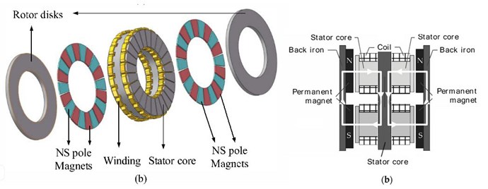
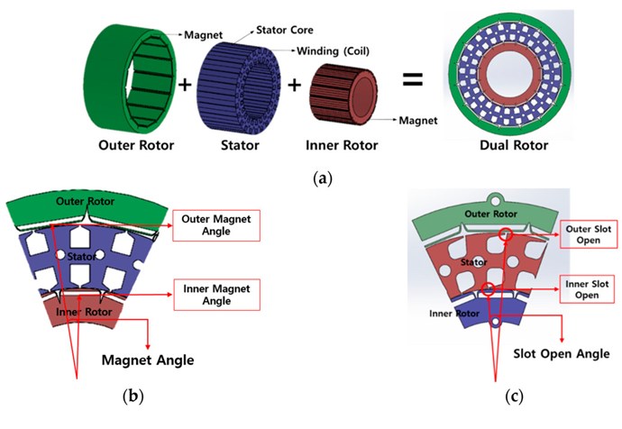
Hey Rakarskiy,
The Acronym:
is what every Serious Researcher should have Concluded by now. Which means, Faradays Law, and Magnetomotive Force are the only Components of Electrical Energy that one must take into account.
Best Wishes,
Chris
Hello Chris!
It would be very reckless to consider the magnetomotive force the only source of "electrical energy"! I dare to note that the term "electrical energy" does not exist in fundamental physics, there is the concept of the energy of an electromagnetic field.
If you compare the two pages from Wikipedia, about "ELECTRIC" ENERGY in English and Russian, you will see a striking difference in the definitions in this matter. Yes, even just in the definitions of what ENERGY is.
In physics, energy is the quantitative property that is transferred to a body or to a physical system, recognizable in the performance of work and in the form of heat and light. Energy is a conserved quantity; the law of conservation of energy states that energy can be converted in form, but not created or destroyed. The unit of measurement in the International System of Units (SI) of energy is the joule, which is the energy transferred to an object by the work of moving it a distance of one metre against a force of one newton.
Common forms of energy include the kinetic energy of a moving object, the potential energy stored by an object's position in a force field (gravitational, electric or magnetic), the elastic energy stored by stretching solid objects, the chemical energy released when a fuel burns, the radiant energy carried by light, and the thermal energy due to an object's temperature.
Mass and energy are closely related. Due to mass–energy equivalence, any object that has mass when stationary (called rest mass) also has an equivalent amount of energy whose form is called rest energy, and any additional energy (of any form) acquired by the object above that rest energy will increase the object's total mass just as it increases its total energy. For example, after heating an object, its increase in energy could in principle be measured as a small increase in mass, with a sensitive enough scale.
Energy (ancient Greek ἐνέργεια - action, activity, strength, power) is a scalar physical quantity, which is a single measure of various forms of movement and interaction of matter, a measure of the transition of the movement of matter from one form to another. The introduction of the concept of energy is convenient because if the physical system is closed, then its energy is stored in this system for the duration of time during which the system will be closed. This statement is called the law of conservation of energy.
From a fundamental point of view, energy is one of three (along with momentum and angular momentum) additive integrals of motion (that is, quantities conserved in time), associated, according to Noether's theorem, with the homogeneity of time, that is, the independence of the laws describing motion from time .
EMF is a dynamic electric vortex field, and Current is a dynamic magnetic vortex field. I understood all this by analyzing the Ampere Force as an element of the formation of the electromagnetic moment of the generator. "The resultant force of Ampere".
More precisely, I thought so before, just with the conduct of experiments, the analysis of these experiments, I became convinced of this with scientific justification.
EMF in the wire of the circuit arises for one reason - this is the balancing of the potential difference of the electric fields of the source, closed in the corresponding circuit.
The most ancient and widespread source is an electrochemical battery. In the electrolyte, an electrochemical reaction occurs with the formation of a potential difference in the electric field between the anode and cathode of the battery. When the anode and cathode are closed, the potentials between them are balanced in an electrical circuit. The EMF of the circuit in this case is not much different from the potential difference between the anode and cathode.
The second source is the charge of atmospheric electricity. We live on a planet that is a spherical capacitor with a constantly changing electric field. If we take the surface of the earth "ZERO" as a reference point, then in the atmosphere we have a belt of positive potential, and in the depths of the earth there are zones of negative potential. This is if you represent the ideal model. It is the charge of objects of the corresponding sign of the electric field that forms gravity (attraction to the surface of the earth). There are a lot of interesting things in this topic: the source of electricity, aircraft, medicine, etc. At one time in Ukraine, a high school student proposed the design of an electrostatic generator to capture atmospheric charge and convert it into loop electricity. The guy was even helped to build and substantiate the idea in one higher educational institution in Ukraine. He received an award at one of the energy forums. After that he was invited to study in the USA, and I never heard anything more about him, as well as about its device.
Electromagnetic induction, the source of an electric vortex field on the surface of a conductor, which is caused by a change in the magnetic field that permeates this conductor when the magnetic field (induction) vector is perpendicular to the length of the conductor. This is the actual effect that all electromechanical or solid state generators use. An electric transformer does not transfer current energy through the core field, only through the mechanism of mutual induction between the conductors. The core is used to accelerate the current strength in the primary circuit of the transformer.
Another way to obtain EMF on the surface of a conductor is electrostatic induction in conductors. "The phenomenon of the occurrence of charges on conductors in an electric field is called electrostatic induction." This phenomenon, in my opinion, is played out in the generators of "Kapanadze", "Stephen Mark" and others. In these designs, in my opinion, the problem of converting a low-cost electrostatic field into a vortex electric field (EMF) is solved.
I hope I have made my point more or less clear.
Best regards, Serge
Hey Rakarskiy,
I agree, but I think its very much more sensible to say, it is reckless to believe in anything that has not one single bit of evidence to support it! There is No Magic here!
Symmetrical Electromagnetic Induction, that Science has offered for the last nearly 200 years is insufficient, however, Asymmetrical Electromagnetic Induction, is the path to Free Energy Machines! There is no denying this! It is Reckless to do so!
We have machines working on this very principle! See Here!
Best Wishes,
Chris

Chris hello!
You are absolutely right, symmetry at rest won't do anything. The EMF itself and the CURRENT POWER of the electric circuit are the result of the asymmetry of the system, which tends to come to symmetry. The magnetic flux that is closed in Ed's keeper has crazy potential inside the ring system, but it is absolutely closed. Only by breaking and closing this ring can a variable magnetic flux be obtained.
There is also a system based on non-linear inductance. Even an ordinary mechanical electric generator receives an EMF in a conductor to change the magnetic induction around the conductor.
The charge of a capacitor is determined by the asymmetry of the field (dipole) of its dielectric. And the discharge is the desire to balance the dipole.
The task of the engineer is to establish the asymmetry and perform power take-off when bringing the system into symmetry.
Sincerely!
OverUnitySystems
https://www.youtube.com/shorts/0LmQzSx06uE
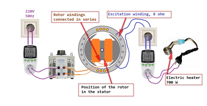 My reader made a very simple and naive experiment. I took the insides of a single-phase generator with excitation (rotor and stator). I made the connection according to the picture. I found the position of the rotor with the stator to be the most optimal (displacement even with an od rod with a groove is fateful) I applied an alternating voltage to the rotor winding. From the stator excitation winding (8 ohms), the guy connected the heating element of the boiler. From the outlet and in front of the heating element, I connected the wattmeters to the circuit.
COP - 3
In all subsequent variants, it was not possible to remove more than 150 watts. The reason is the absence of a rotational field in the stator.
We are solving this problem.
Full analysis of the experiment. It is very clearly seen how the generator phase and the secondary of the transformer differ.
https://rakatskiy.blogspot.com/2022/06/static-electromagnetic-transducer.html [Static electromagnetic transducer experiment [COP>1]]
Hi Rakarsky
congratulations for the cop3
Tell me what is the operating frequency of your system?
Given that you took your measurements with a device that operates at 50 hertz, it must be very low?
I don't really understand the basic principle of this system, how does it generate overunity?
Jagau
Hi Rakarskiy!
I tried to replicate your experiment. Took wash-machine motor, measured the stator, it was also 8 ohms.
Rotor has only 2 leads (wires), blue and white - it goes to the brushes. I tested that the motor worked well.
So after that I put in 0..110VAC to the brushes and had the load and scope metering on the secondary and the load. Secondary was the stator having 3 leads (black centre and other colorful leads).
The voltage went hardly over 4VAC on the secondary and the input was 200-250W. (My autotransformer eats at least 40W.)
Raivo
Good Time Seekers!
The experiment was carried out on a standard ROTOR + STATOR pair of a single-phase 220V generator with self-excitation.
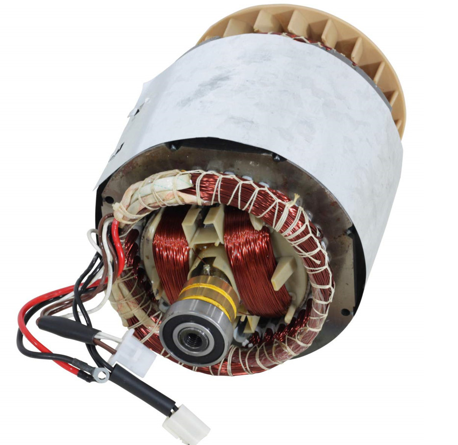
The rotor windings are connected in series and connected to the output of a laboratory AC transformer (LATR). The LATR input is connected via a wattmeter to a 220V 50Hz socket. At the output from the stator, an excitation winding (8 ohms) is used, to which a 700W / 220V water heater is connected.
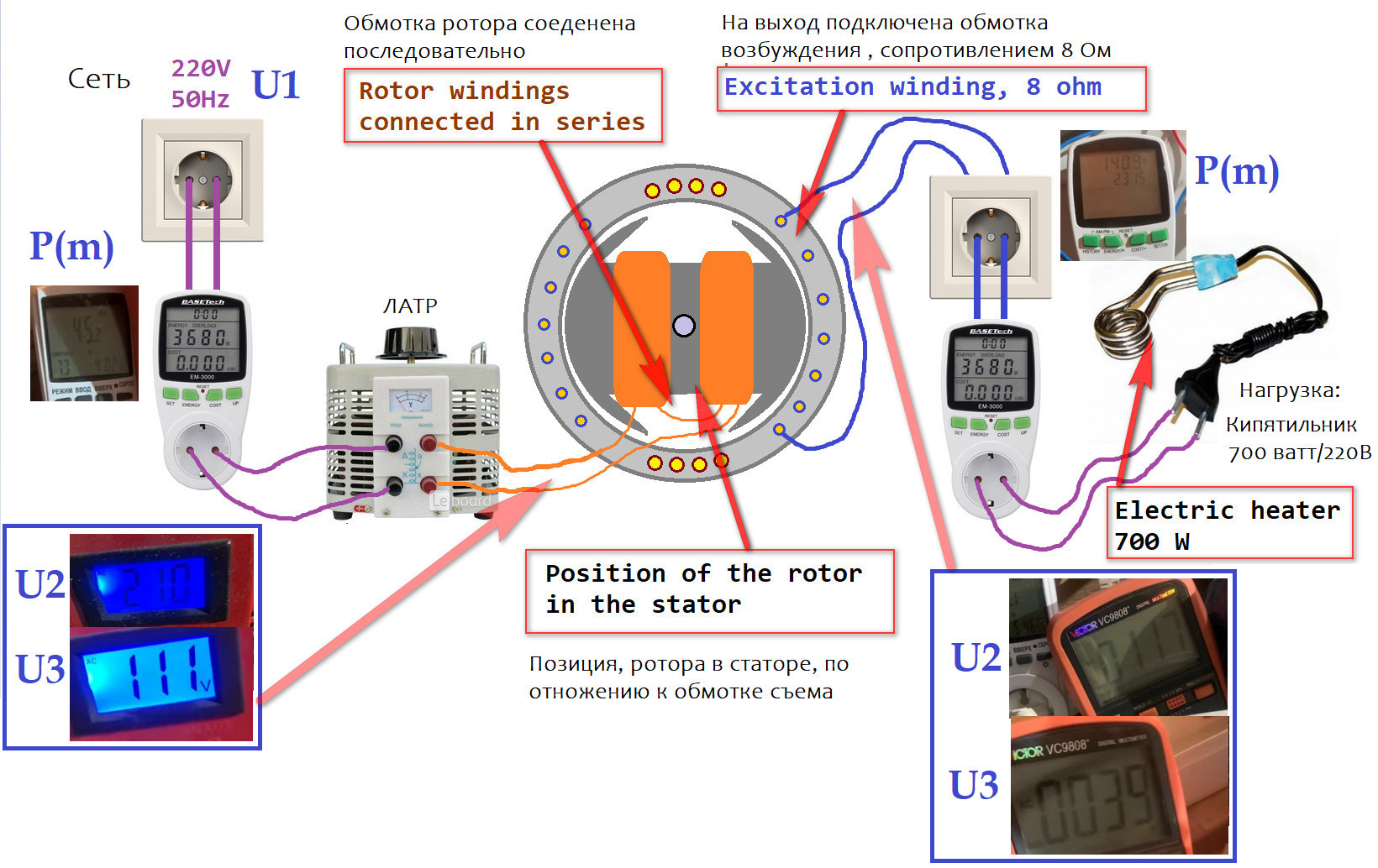
It is necessary to find the position of the rotor in the stator, for excellent coupling of the magnetic flux of the rotor-stator pair. An offset of even half the area of the shaft groove matters. We need to look for this position.
Real efficiency - 2.0, almost the same as Robert Holcomb positions in this material of his:
Best regards to all seekers!
Thanks for sharing Rakarskiy
Can I ask what brand / model motor are you using?
Kind regards
Brian
Thanks for sharing Rakarskiy
Can I ask what brand / model motor are you using?
Kind regards
Brian
I do not know the exact model, this is a rotor-stator pair for a 5 kW generator.
The problem is that the rotor is not designed to be connected to AC. The rotor is an electromagnet with a direct current connection, with a variable current strength parameter, to control the level of primary magnetic induction in the circuit.
The second pole pieces do not have the same gap over the entire plane, this is done to obtain a sinusoidal EMF.
Sincerely.

My Friends,
I would like to point out, Father Antonio D'Angelo invented an almost identical machine, way back in March 7, 1928.
The above link has all the information you need to see this fact!
It would be careless to say this is Holcomb's Invention, its an almost exact copy!
Best Wishes,
Chris
Chris, good stuff, but it's a single armature dynamic motor converter!
I figured out there indeed the anchor is motionless! good find!
Classifications: H02K47/16 Single-armature converters, e.g. metadyne
https://patents.google.com/patent/US2021177?oq=US2021177
Robert Alexander and Nikola Tesla, also devices of Germany 1942-1945.
https://rakatskiy.blogspot.com/2021/02/mystery-nikola-teslas-electric-car.html
In the USSR, it was in 1959 Leonid Stovbunenko, the recognition of the personality was classified by the commission of the military-industrial complex of the USSR. His electric car drove around Leningrad all day and the battery charge was not discharged.
This generator is directly related to the principle of generating electricity by Clemente Figuer, Dr. Holcomb, and even a conventional mechanical synchronous generator. Speed begets speed.
http://www.rexresearch.com/russellcoil/russellcoil.htm
Sincerely!
This guy also decided to repeat the experiment with the rotor and side of a single-phase generator
He had a position when he received a decent result of the transformation.
https://overunity.com/19069/holcomb...-technology-to-the-world/msg568427/#msg568427
COP = Рout/Pin = (65V*1.6A=104W / 25.3V*0.6A=25.9W) = 4.0!
My recommendation to him:
****
If you want to try the self propelled option, you will need a voltage balancing system, it is better to rely on the battery. From battery via DC/AC converter to rotor winding. From phase through AC/DC charger to battery. Connect the load to the battery.
Hi,
This meter cannot measure current and voltage at the same time. It is most possibly a measurement error.
There is no energy dissipation of 104W level (lightbulb is quite dim).
--Raivo
My Friends,
I agree with Raivo!
A DMM, Digital Multi Meter will trick you very often! Be very careful with them! Pretty much, DC or AC at 50/60 Hz is all you can really be sure on.
A Scope with Precision Measurement equipment will save you a ton of Pain! Worth the investment if you think you have something!
Best Wishes,
Chris
measurements? I analyzed my reader's first experiment!
https://rakatskiy.blogspot.com/2022/06/static-electromagnetic-transducer.html
You just need to understand what and where you measure. Whether he is right or not, I think the guy will figure it out, in any case, the result will be Over Unity.
Hello Rakarskiy,
We merely offer advice, which comes from experience.
Lets say the incandescent globe is rated for 100 Watts @ 240 Volts AC. This gives a Resistance of: 576 Ohms.
Now using this value of resistance, and using the 64.2 Volts shown in the video, we get: 0.11146Amps and a total of: 7.15563 Watts.
Therefore the measurement he provides as Current: 1.617 cannot be correct can it?
We all started where this guy is! This guy is doing really well! We want builders!
Send him the link to our Measurement Protocol Thread as an assist!
Like I said this will save a lot of heart ache!
Above unity is very easily possible! Don't give up! Only, if you wish to provide Measurements make sure they are Solid and Un-Refutable!
Here is two examples of Un-refutable Machines:
The same Ohms Law Test can be applied to Captainloz's Machine, but the Trolls Neglected to do the most obvious first! What a Coincidence! I have already pointed this out to them Here, but I guess they disbelieve in Ohms Law?
We have many more! Machines that must be understood to be able to build, but we provide all information required!
You have a good concept! Don't give up!
Best Wishes,
Chris
Good time Chris!
I rely on his data from this post:
(True, the guy does not specify what he measured. I rely that these are current indicators (in a series circuit under load) and voltage at the terminals of the rotor and phase under load.)
The guy's problem is the lack of the necessary equipment.
In his case, as in any other, it is most effective to compare by DC parameters, due to the lack of DC power factor. To analyze not a moment but a full cycle of operation, this will be a lot of painstaking work.
I gave him my proposals, he probably ignored them. The reason is still the lack of a sufficient material base for carrying out force measurements.
Sincerely!


No one online at the moment
Past Visitors: 0 | Live Visitors: 0
3D globe widget by: Chris Sykes
In physics, scalars are physical quantities that are unaffected by changes to a vector space basis. Scalars are often accompanied by units of measurement, as in "10 cm". Examples of scalar quantities are mass, distance, charge, volume, time, speed, and the magnitude of physical vectors in general.
You need to forget the Non-Sense that some spout with out knowing the actual Definition of the word Scalar! Some people talk absolute Bull Sh*t!
The pressure P in the formula P = pgh, pgh is a scalar that tells you the amount of this squashing force per unit area in a fluid.
A Scalar, having both direction and magnitude, can be anything! The Magnetic Field, a Charge moving, yet some Numb Nuts think it means Magic Science!
Hello my children. This is Yahweh, the one true Lord. You have found creation's secret. Now share it peacefully with the world.
Ref: Message from God written inside the Human Genome
God be in my head, and in my thinking.
God be in my eyes, and in my looking.
God be in my mouth, and in my speaking.
Oh, God be in my heart, and in my understanding.
We love and trust in our Lord, Jesus Christ of Nazareth!

More than anything else, your contributions to this forum are most important! We are trying to actively get all visitors involved, but we do only have a few main contributors, which are very much appreciated! If you would like to see more pages with more detailed experiments and answers, perhaps a contribution of another type maybe possible:
They REFUSE to tell me why!
The content I am sharing is not only unique, but is changing the world as we know it! Please Support Us!
Thank You So Much!
Chris
260
 ElectroMike
84
ElectroMike
84
 AETHERIC_MIND
50
AETHERIC_MIND
50
 FringeIdeas
50
FringeIdeas
50
 GuruNandan
50
GuruNandan
50

Ere many generations pass, our machinery will be driven by a power obtainable at any point of the universe. This idea is not novel. Men have been led to it long ago by instinct or reason. It has been expressed in many ways, and in many places, in the history of old and new. We find it in the delightful myth of Antheus, who drives power from the earth; we find it among the subtle speculations of one of your splendid mathematicians, and in many hints and statements of thinkers of the present time. Throughout space there is energy. Is this energy static or kinetic? If static, our hopes are in vain; if kinetic - and this we know it is for certain - then it is a mere question of time when men will succeed in attaching their machinery to the very wheelwork of nature.
Experiments With Alternate Currents Of High Potential And High Frequency (February 1892).