Itsu replication RMS versus Average

  • 693 Views
  • Last Post 27 July 2022
Jagau posted this 20 July 2022

Since Itsu is not a member here ( I hope he will one day) and since we sometimes exchange ideas, I asked his permission to pass on his experiences on the RMS average comparison,  As we have to examine the question from different angles this is of interest.


From Itsu

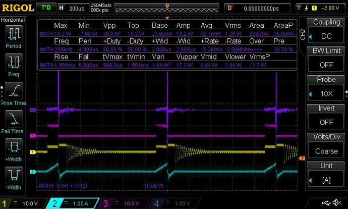
OK, now using a 12V / 5W lamp, same setup 1Khz @ 10% duty cycle:


Screenshot shows the:
 
# voltage in yellow across the 12V / 5W bulb
# current in green through the 12V / 5W bulb (current probe)
# Power in red calculated by the scope (Ch1 x Ch4)
 
I measure BETWEEN the 2 yellow vertical cursors only, so all data in the result box ONLY points to data take from the traces between those cursors which is 1 full period (cycle)
 
So we see that this period (1ms long) has a mean value of 1.166V and a rms value of 3.755V, and the current measures 192.9mA rms for which the scope calculated power (red) to be 723.6mW.
 
I have put 2 DMM's across the 12V / 5W bulb and:
 
# the Fluke 179 true RMS meters says 1.174V
# A cheapo DMM (no true rms) says 1.168V
 
Both DMM's of course measure the whole signal, so many periods (cycles).
 
It shows that a pulsed DC square signal has different value's for Vavg and Vrms.
 
The 12V bulb is on, but dim, so the 723mW seems an OK value for this 5W bulb.
Therefor the Vrms value of 3.755V seems the correct one as 3.755 x 0.1929 = 724mW which is the same almost as the scope calculates.
So both DMM's show the wrong voltage as they show the average voltage (mean) which cannot be used for this power calculation.
 Itsu


 My experience with this setup:
 
10 Ohm 1% CSR loaded with 10V DC pulse 1KHz @ 10% duty cycle.


Screenshot shows the:
 
# voltage in yellow across the 10 Ohm
# current in green through the 10 Ohm (current probe)
# Power in red calculated by the scope (Ch1 x Ch4)
 
I measure BETWEEN the 2 yellow vertical cursors only, so all data in the result box ONLY points to data take from the traces between those cursors.
 
So we see that this pulse (98us long) has both mean and rms value of 10V, and the current measures 1.01A for which the scope calculated power (red) to be 10.1W.
 
I have put 2 DMM's across the 10 Ohm resistor and:
 
# the Fluke 179 true RMS meters says 0.984V
# A cheapo DMM (no true rms) says 0.978V
 
Both DMM's of course measure the whole signal, so including the 10% duty cycle, therefor its ~10 times lower in value.
 
Not sure what you want with this, but it shows to me that a pulsed DC square signal has the same value for Vavg as for Vrms.


For the melnichenko setup, i yesterday tried 3 different methods to measure / calculate the input power:
 
 
1) using my voltage and current probe at the PS entry of the circuit.
    This shows i have 36V DC @ 129.7mA rms AC for which the scope math function calculated the mean power to be 4.42W
 
2) using your method "Urms_pulse=Vp√D" where for:
    voltage my t1 is 72us and T is 770us thus D = 0.093, Vp is average 32.9V, so giving Vrms to be 10.06V rms
    current my t1 is 72us and T is 770us thus D = 0.093, Ip is 2.8A, but triangled, so halved for square so is 1.4A, so giving I rms to be 427mA rms
    Power then is V rms x I rms = 10.06 x 427mA = 4.29W
 
3) A 2th way to calculate I rms in the above 2) method is to use the triangle formula "Urms_triangle_ = Vp√t1/3T" which gives 2.8A x √72/3*770 = 2.8A x 0.1765 = 494mA rms
    This multiplied by Vrms 10.06V gives 4.97W
 
So we got input powers: 4.42W, 4.29W and 4.97W by different measurement / calculations.
Each method has its own parameters, and although i tried to measure them as best as i can, none will be exactly right due to several fluctuations thus this outcomes.
But overall, if i would have to pick the most correct one i will vote for method 1.

Jagau for Itsu

All ideas are interesting to observe as you can see

Jagau

Order By: Standard | Newest | Votes
Chris posted this 20 July 2022

Thank You Jagau for sharing this data!

@All Readers:

The fact of the matter is, some will not accept that taking RMS on DC Pulsed Systems is simply wrong!

TinselKoala, TK has a very extensive history in Metrology and he uses Mean, recommends to NOT use RMS:

which generates an instantaneous power waveform, then take the _average_  (not RMS) value of that IP waveform.

Ref: Accurate Measurements on pulsed system's harder than you think.

Interesting read, observe Names and Recommendations for more insight!


Tinselkoala would be shaking his head at this non-sense! The truth of the matter is RMS is wrong for DC Pulsed Measurements and the Guru's will not admit it even in the face of Evidence! They are fooling themselves into Fakery and trying to fool others into the very same Fakery!

I care not for them, I care for those that get fooled and accept the Lies! I have pointed out before, there is a very good reason they insist on RMS, because they can fudge the figures with RMS on DC Pulsed Systems!

How you ask:

Of course, a DC Power Source is Incapable of Supplying Negative Conventional Current when it is designed to Supply a Positive Conventional Current!


EG:

  • 1.28 Watts RMS
  • 0.0957 Watt's Average


They insist that all that Negative Current is used Current, when it is not, and its very easily shown its not!

They fool you by lying to you and misleading you, but hey, if you allow them to do so, then I can not help you! You can not help yourself, there is nothing that can be done! In the light of evidence, some will still opt for the simple route and allow themselves to be suckers for the Lies!

Those that insist on RMS in the face of Evidence are either:

  1. Attempting to mislead you!
  2. Not smart enough to see the evidence!


My Friends, watch for the active propaganda, its everywhere, they do not want you to see the truth!

We are so far ahead, we are Light Years Ahead of the other Forums, we are so far ahead, that they may as well be playing at kindergarten!

Best Wishes,

   Chris


EDIT: Itsu is courageous and must be admired for his efforts! He is investigating what the others refuse to! Itsu needs to be commended for his work and effort to investigate what others can not grasp!

Jagau posted this 20 July 2022

I admire Istu's courage to come up with open ideas like that.
thank you, Itsu a real experimenter who performs interesting experiments.
Jagau

Chris posted this 21 July 2022

I agree Jagau,

Its a shame that Itsu does not have a single friend helping his effort to get to the bottom of what should be a simple subject that is not only obvious, but can be proven beyond a doubt in many situations.

Some of those people are the very same people that tried to throw me under the Bus for showing Scope pictures with AC Coupling...

Now they are totally vacant... WTF?

As there is a debate going on on AboveUnity.com concerning the use of rms versus average (mean) value's and/or the use of DDM's (true rms or not) for calculating power, the focus seems shifted off from the "Melnichenko effect" replication.

I always try to avoid using rms and/or average value's or the use of DDM's for calculating power and use the scope to do that for me using its math function to calculate many thousands instantaneous voltage and current samples (V x I) to arrive at the instantaneous power value's for the scope screen or buffer which then get averaged across that screen or buffer to get the average power.

Its the only reliable thing to do IMHO as the scope does not care if the presented signals are DC, AC, pulsed, spiky or whatever nor if its shown as rms, mean, p2p or whatever.

So while waiting for the members there to focus again on the "melnichenko effect" replication, i will try to explore the original melnichenko circuit (so not the present circuit which was slightly modified by Jagau) to see if any special effects can be noticed when using that one.

Ref: A Melnichenko effect replication


A very interesting set of statements, don't you think? Itsu did start this experiment rolling, and he must use one or the other! The Scope wont do any Cals other wise! Mean or Average should be used, across DC Pulsed Data that may contain a Non-Linear Load, as in the Input Coil, this is right! NOT RMS! However, RMS is correct for AC with Linear Loads! I think Itsu has seen the light!

There really is no debate, its an experiment, with Data and Calculations, to Light up the Darkness!

Itsu is way ahead of these other members over there, even though Itsu still has not learned the ropes to what we are sharing, he is getting a lot closer and soon will go quiet, not publishing anything, because he has succeeded.

It would be nice to have Itsu join us, but he turned down the invite. I know sometimes I can be a bit difficult, but without being difficult, perhaps we would not be so far ahead. Sometimes one has gotta stick to your Guns to win the War! We have made so many other forums Obsolete! Because of our progress.

Best Wishes,

   Chris

  • Liked by
  • Augenblick
  • Jagau
Chris posted this 22 July 2022

My Friends,

An Update:

Hi Itsu,

This approach is the best to use but it needs to have a correct, two channel digital oscilloscope. 
There is another approach for those who have analog or other scope types with no Math function.

If a home experimenter, using his scope can measure the peak current his coil draws at the switch off moment and knows the inductance of the coil, then he can calculate the instantaneous energy (and power) the coil just possesses.

Here is the well known formula to calculate how much energy a coil receives from an input current:
   E = 1/2 * L * I² 

Let's take as an example your 3 Amper peak current measured for your old L1 coil shown in your Reply #1 https://www.overunityresearch.com/index.php?topic=4312.msg99509#msg99509

Your L1 coil inductance was 726 uH (without the L2+core), switching frequency was 1.4 kHz with about 9 % duty cycle as you wrote.

Using this online calculator  https://physicscalc.com/physics/inductor-energy-calculator/  for the stored energy in coils, we get E = 0.003267 Joule.

Your ON time may have been 64.2 us (based on the 9 % duty cycle, and one full cycle time was T = 1 / f = 714.2 us).  So the L1 coil received 3 A current pulses at each 714.2 usec.  Multiplying the stored energy,  E = 0.003267 J by the 1400 Hz input frequency (or dividing it by T=714.2 us), we get 4.57 Watt, this is very close to your scope's Math calculated 4.63 W result for the input power by multiplying the instantaneous DC input supply voltage and the input current (2nd scope shot in your Reply #1 above). 

So the available magnetic energy (at the switch-off moment of the input current) in your L1 coil was 0,003267 Joule. This amount of energy calculated by the formula does not include the switching and the coil (and core) losses, these should be separately considered to get the full input energy (and power) taken from a power supply. These losses are relatively low or can be kept low. 

Gyula 

Ref: A Melnichenko effect replication


And Itsu's Reply:

Gyula,

thanks so much, so like we can calculate the energy in a capacitor (different formula of course), we can with your formula (E = 1/2 * L * I² also calculate the amount of energy in a coil.


So we can add a 4th method to measure / calculate the input power:


1)  using a voltage and current probe at the PS entry of the circuit.
    This shows i have 36V DC @ 129.7mA rms AC for which the scope math function calculated the mean power to be 4.42W

2)  using a method presented by Jagau "Urms_pulse=Vp√D" where for:
    voltage my t1 is 72us and T is 770us thus D = 0.093, Vp is average 32.9V, so giving Vrms to be 10.06V rms
    current my t1 is 72us and T is 770us thus D = 0.093, Ip is 2.8A, but triangled, so halved for square so is 1.4A, so giving I rms to be 427mA rms   
    Power then is V rms x I rms = 10.06 x 427mA = 4.29W

3)  A 2th way to calculate I rms in the above 2) method is to use the triangle formula "Urms_triangle_ = Vp√t1/3T" which gives 2.8A x  √72/3*770 = 2.8A x 0.1765 = 494mA rms
    This multiplied by Vrms 10.06V gives 4.97W

4) Gyula's presented formula E = 1/2 * L * I² which for the data presented in method 2) gives 1/2 * 0.000951 * 2.8² =  0.00372792 Joule  (using 951uH for L1 and running at 1.3Khz 10% duty cycle).
    Divided by the 770us period, it shows 0.00,372792 / 770 = 4.84W.

So we got input powers: 4.42W, 4.29W, 4.97W and 4.84W by different measurement / calculations.

Each method has its own parameters, and although i tried to measure them as best as i can, none will be exactly right due to several fluctuations thus these outcomes.

But overall, if i would have to pick the most correct one i will vote for method 1.

Regards Itsu

Ref: A Melnichenko effect replication


Amperes Law gives us an Approximation:

The energy of a capacitor is stored in the electric field between its plates. Similarly, an inductor has the capability to store energy, but in its magnetic field. This energy can be found by integrating the magnetic energy density,

{u}_{\text{m}}=\frac{{B}^{2}}{2{\mu }_{0}}

over the appropriate volume. To understand where this formula comes from, let’s consider the long, cylindrical solenoid of the previous section. Again using the infinite solenoid approximation, we can assume that the magnetic field is essentially constant and given by B={\mu }_{0}nI everywhere inside the solenoid. Thus, the energy stored in a solenoid or the magnetic energy density times volume is equivalent to

U={u}_{\text{m}}\left(V\right)=\frac{{\left({\mu }_{0}nI\right)}^{2}}{2{\mu }_{0}}\left(Al\right)=\frac{1}{2}\left({\mu }_{0}{n}^{2}Al\right){I}^{2}.

With the substitution of (Figure), this becomes

U=\frac{1}{2}L{I}^{2}.  


Ref: Energy in a Magnetic Field


At least there is some now helping Itsu! This is  win for Itsu! Finally! Even if they are presenting an Approximation as a proof, its better than nothing at all!

Best Wishes,

   Chris

  • Liked by
  • Augenblick
scalarpotential posted this 23 July 2022

Hi,
I think TinselKoala is saying that when the instantaneous power P(t)=V(t) x I(t) is shown as a math signal, the average of this signal should be used and not the rms feature, because Prms doesn't exist.
My not yet proven statement is (will try to prove this later with math, a DSO is using complex math too): This P_avg calculated from the sum of instantaneous V&I (what TK is saying) is equal to Vrms x Irms, because Vrms & Irms are integrations of squares. Remember that the definition of P is a continuous rate, per second.
I'm not saying which method one should or shouldn't use, am just thinking and learning along.

Regards!

  • Liked by
  • leonel
  • Augenblick
Chris posted this 24 July 2022

Hey Scalarpotential,

The Definition of Power is:

  • DC Power P = Voltage V x Current I
  • AC Power P = Voltage V x Current I x Cos ( Theta θ )


The conversion of Power to Joules is: Joules J = Power P x Time t


Instantaneous Power P

Ref: Instantaneous Power


How the Scope Works


The Oscilloscope Measures Instantaneous Power P by Integrating the Oscilloscope's Data Buffer:


Checking Oscilloscope Measurements should always be done Mathematically:


No, Approximations simply are not close enough!

Finally some sense Here, see why we are world Leaders in Measurement!

Ohms Law will give you your solution and its not RMS for a DC Pulse! Integrating V x I over time for the 50% Duty Cycle as I have shown, gives you the same answer I have given you already here: Chris's Waveform Experiment, RMS vs Average


This is true, weather you like it or not, sorry!


In the below video, Tektronix tells you what RMS is for: @ 4 : 40


Best Wishes,

   Chris

  • Liked by
  • baerndorfer
  • Augenblick
scalarpotential posted this 26 July 2022

Thanks Chris for writing out.
RMS has one function, which is calculating the effective or average dissipated power of a varying signal. The peak power is calculated from the amplitude of V&I and cos(theta), result is peak power, if you integrate the instantaneous power and divide the result by the period, it gives the average power, deriving V and I from this value by using ohm's law gives the RMS values of V & I, which mean nothing except when you want to know the effective power rate.
For DC, 50% duty cycle, 2V, 2A:
Vrms = 2 x sqrt(50/100)=2 x 0.707V
Arms = 2 x sqrt(50/100)=2 x 0.707A
Pavg = 2 x 2 x 0.707 x 0.707 = 2W
note sqrt(50/100) x sqrt(50/100) = sqrt(0.5) x sqrt(0.5) = 0.707 x 0.707 = 0.5
What is the average power if you'd calculate it yourself without RMS for such a signal?

  • Liked by
  • Augenblick
scalarpotential posted this 26 July 2022

  • Liked by
  • Augenblick
Chris posted this 26 July 2022

Scalarpotential, Did you actually read the image you posted?

They say, very clearly:

sinusoidal voltage


I am getting tired of this topic, and wont be responding any more, I have done my homework and know RMS is wrong for a DC Pulsed Waveform, I think others also need to do a bit more home work!

Best Wishes,

   Chris

  • Liked by
  • Augenblick
  • strape
scalarpotential posted this 27 July 2022

If you want to know the effective power of a device, math function v(t) x i(t) must be used and the math signal must be averaged. But the product of the RMS measurements of both v(t) and i(t) gives the same answer. Also for pulsed DC. See for yourself. A scope that allows the math function v(t)^2/r or i(t)^2 x r if load resistance is known should give the same signal.


Yes, 1/sqrt(2) is only suitable for sinusoidal signals. The RMS formula for DC pulses happens to give sqrt(t/T) - t=duration dutycycle, T=period - which Jagau also has shown. RMS is usable for all periodic signals (that can be described by a function) as a continuous DC equivalent (see image), scopes don't know the function but just computes with the datasamples. Try to understand how it is derived. I was new to RMS until I read your topic and researched it.

Now  (I think) I know how to understand and calculate the effectiveness of the POC output signal.


  • Liked by
  • Chris
scalarpotential posted this 27 July 2022

Chris, I think I see what you mean, can't just multiply Vrms and Irms that the scope calculates, because that's only the apparent power VA (..?), instead must use avg of math to get the real effective power rate.

  • Liked by
  • Augenblick
  • Chris
Chris posted this 27 July 2022

Hello Scalarpotential,

Not really correct when you say:

that's only the apparent power VA (..?)


Any point, that the Instantaneous V x I = 0, it must be Zero, and with RMS its not! RMS says V x I for almost 71% of a 50% duty Cycle says power must be there - of course this is in accurate and shows a very obvious error in measurement.

I respect all wanting to learn, I am also learning, lets all learn together.

One must always remember, the Instantaneous Voltage Potential Measurements is what counts here as this is the Area under the Curve, and therefore any Value greater than Zero or Less that Zero is Potential that is not Zero. We must therefore work out where this Data Under the Curve has come from. Then we must integrate and average the values only using RMS for Alternating Current with Linear Loads. If the Load is Non-Linear, then we must realize this and account for this.

I have found another major error in Sciences Math and will be putting this up at some stage.

Best Wishes,

   Chris

  • Liked by
  • Augenblick
We're Light Years Ahead!
Members Online:
What is a Scalar:

In physics, scalars are physical quantities that are unaffected by changes to a vector space basis. Scalars are often accompanied by units of measurement, as in "10 cm". Examples of scalar quantities are mass, distance, charge, volume, time, speed, and the magnitude of physical vectors in general.

You need to forget the Non-Sense that some spout with out knowing the actual Definition of the word Scalar! Some people talk absolute Bull Sh*t!

The pressure P in the formula P = pgh, pgh is a scalar that tells you the amount of this squashing force per unit area in a fluid.

A Scalar, having both direction and magnitude, can be anything! The Magnetic Field, a Charge moving, yet some Numb Nuts think it means Magic Science!

Message from God:

Hello my children. This is Yahweh, the one true Lord. You have found creation's secret. Now share it peacefully with the world.

Ref: Message from God written inside the Human Genome

God be in my head, and in my thinking.

God be in my eyes, and in my looking.

God be in my mouth, and in my speaking.

Oh, God be in my heart, and in my understanding.

Your Support:

More than anything else, your contributions to this forum are most important! We are trying to actively get all visitors involved, but we do only have a few main contributors, which are very much appreciated! If you would like to see more pages with more detailed experiments and answers, perhaps a contribution of another type maybe possible:

PayPal De-Platformed me!

They REFUSE to tell me why!

We now use Wise!

Donate
Use E-Mail: Chris at aboveunity.com

The content I am sharing is not only unique, but is changing the world as we know it! Please Support Us!

Thank You So Much!

Weeks High Earners:
The great Nikola Tesla:

Ere many generations pass, our machinery will be driven by a power obtainable at any point of the universe. This idea is not novel. Men have been led to it long ago by instinct or reason. It has been expressed in many ways, and in many places, in the history of old and new. We find it in the delightful myth of Antheus, who drives power from the earth; we find it among the subtle speculations of one of your splendid mathematicians, and in many hints and statements of thinkers of the present time. Throughout space there is energy. Is this energy static or kinetic? If static, our hopes are in vain; if kinetic - and this we know it is for certain - then it is a mere question of time when men will succeed in attaching their machinery to the very wheelwork of nature.

Experiments With Alternate Currents Of High Potential And High Frequency (February 1892).

Close