Chris
posted this
22 December 2020
- Last edited 22 December 2020
Hi John,
Excellent to see! You will notice I have moved your post out to its own thread, this will help you and everyone else help, and keep progress.
First up: Thank You for Sharing!
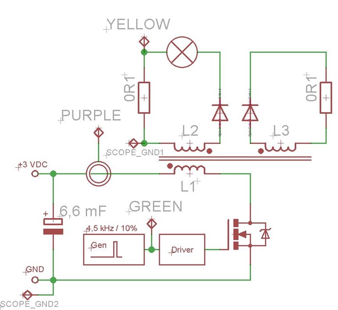
Don't change anything except for the Concrete Resistor, that needs to be replaced, and that's all.
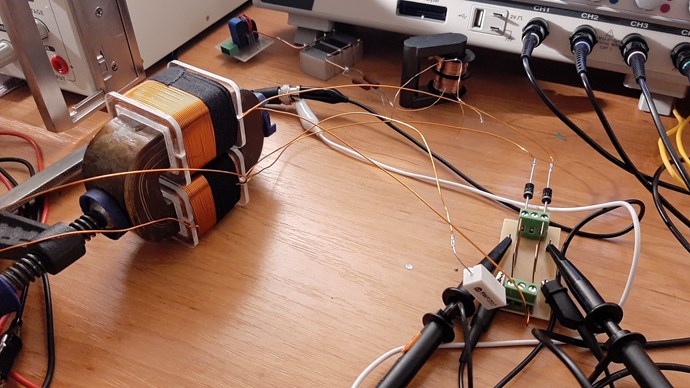
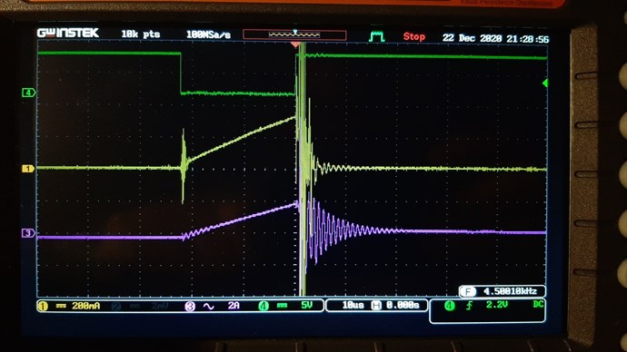
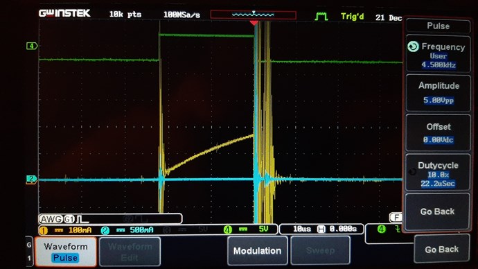
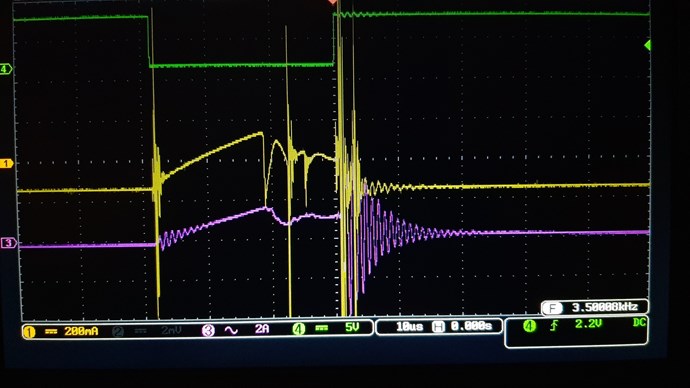
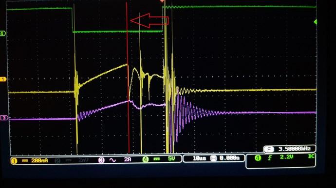
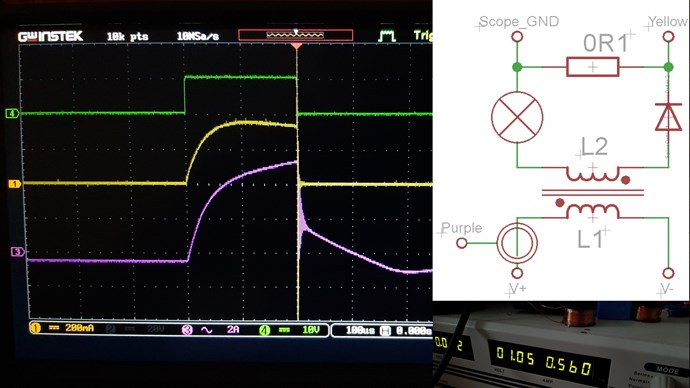
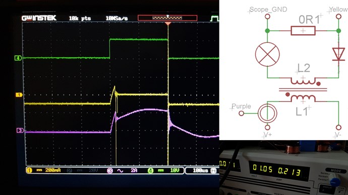
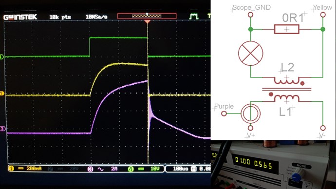
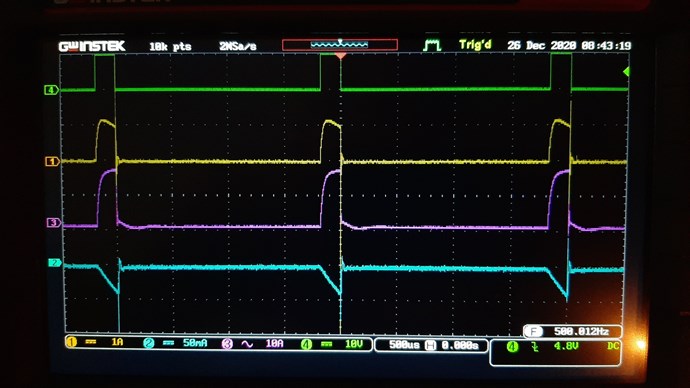
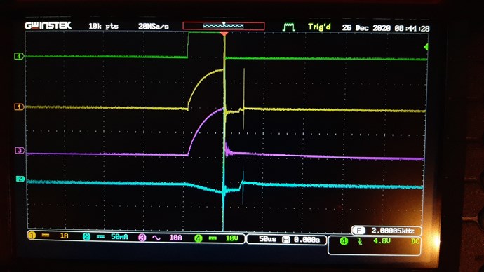
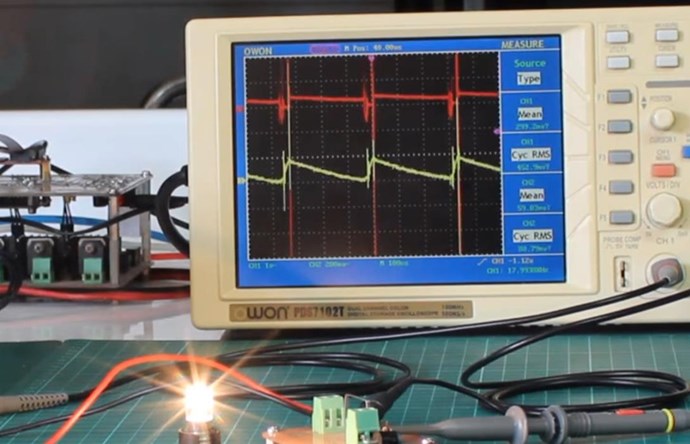
Scope Shots, are showing a few things. We don't see the Asymmetrical Sawtooth Waveform, but we will get you there.
Start by following the following procedure:
- Keep the Input Coil Polarity as it is.
- Disconnect entirely, L3.
- Get L1 and L2 in Transformer Mode, use the Right Hand Grip Rule to make sure the Polarity is right, remember Opposing.
- Once you have this done, then Connect L3, this has 2 Polarities, one will work and you will get the Asymmetrical Sawtooth Waveform, and one you wont. Find the one that does give you the Asymmetrical Sawtooth Waveform.
- Then, tune Input and Input Coil to match optimum Output Result.
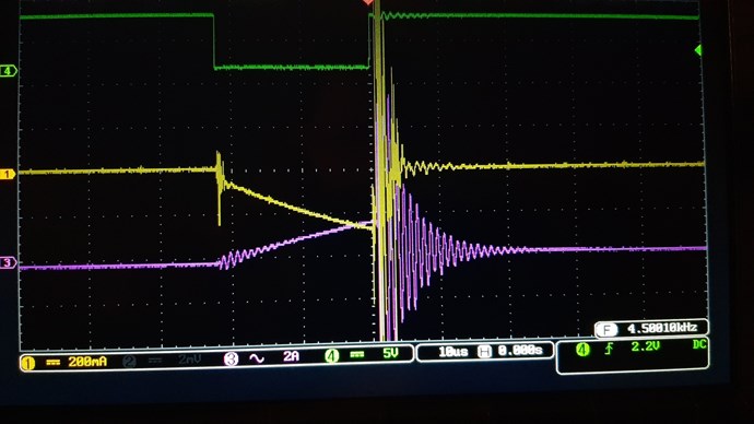
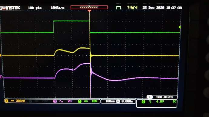
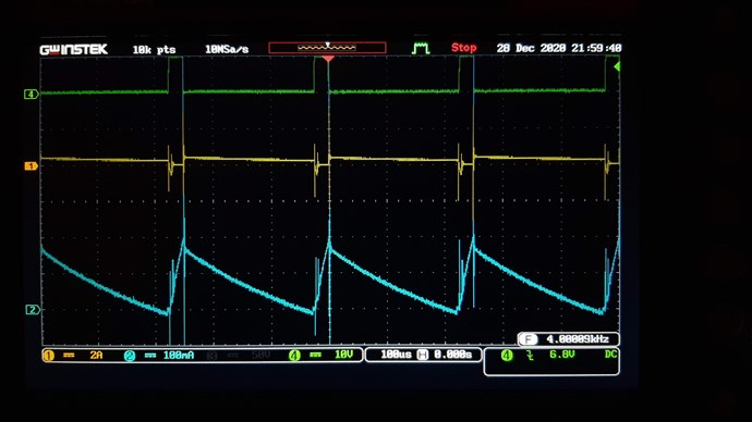
The Asymmetrical Sawtooth Waveform on the Output:
The Lengths of the Coils play a role here. The Run Frequency should be a Fundamental Resonant Frequency, or a Harmonic of the Fundamental. At Harmonics, one will need the Input Voltage to go up by the same factor. We try to aim for 1/4, or Quarter Wave length of the Partnered Output Coil and the Primary, so this would mean, if a single Partnered Output Coil is 100 meters, the Input Coil would need to be 25 meters.
Resonance does not need to be 100's of KHz!
I often have my machines running down around 3 to 5 Khz, sometimes less. So don't let "Conventional Wisdom" lead you astray!
The Effects you observe are where the Path Forward lays! So let your instinct and intuition lead you, not your "knowledge"! Knowledge is a dangerous thing, especially when one can not distinguish between observation showing incompleteness and inaccuracy's, in that Knowledge! I have seen this many times from so called experts in the field! They get angry when they can not explain very simple things they have not ever observed before! So beware of those people!
Your Input Coil needs to be completely off after the Initial Pulse, see here:
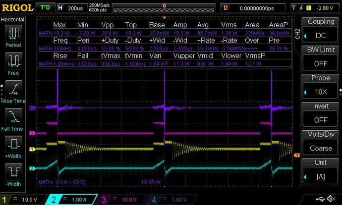
The Power, seen here, Changes! After Switch Off, we see: 1 x -1 = -1, see the Argand Diagram for more information.
A much greater number can be sent back to your Power Supply, once you have the correct operation, here is an example:
Input Power Drops 68% Under Load!
Lastly, don't give up! You have a World Leading Team of Experts here! Something you will not get anywhere else! We will help! So be patient and force your mind to think Simple! Don't over Complicate this!
Thank You for Sharing!
Best Wishes,
Chris