My Friends,
Many years now I have been super interested in PWM. Years ago I wrote a PWM project for Arduino, it was terrible, but it was a good start. Since then, I have written many more...
Today I want to share something of a bit more value than my first project, A PWM Project that has a lot more value:
The Code:
////////////////////////////////////////////////////////////////////////////////////////////////////
// PWM Software written by Chris Sykes.                                                           //
// NOTE: 16 bit Timers currently used. 32 Bit Timers need all shorts changed to longs!            //
// Software written and shared as is, no warrantys are given. Use at your own risk.               //
////////////////////////////////////////////////////////////////////////////////////////////////////
// Your MCU Clock Frequency: 16000000 or 16e6, retrieved by F_CPU.                                //
long fclock = F_CPU;


////////////////////////////////////////////////////////////////////////////////////////////////////
// Most MCU's have:                                                                               //
//   0,                                                                                           //
//   8,                                                                                           //
//   64,                                                                                          //
//   256,                                                                                         //
//   1024                                                                                         //
// as Prescaler Values:                                                                           //
short Prescaler = 1024;


////////////////////////////////////////////////////////////////////////////////////////////////////
// The MCU Setup Method:                                                                          //
void setup() {//////////////////////////////////////////////////////////////////////////////////////

  // Init Serial:
  Serial.begin(115200);

  // Confgure Timer:
  ConfgureTimer(1.275, 21.525);
}


////////////////////////////////////////////////////////////////////////////////////////////////////
// Configure Timer:                                                                               //
void ConfgureTimer(double frequency, double dutycycle){/////////////////////////////////////////////

  // The counter simply overruns when it passes its maximum 16-bit value
  // (MAX = 0xFFFF (65535)) and then restarts from the BOTTOM (0x0000).

  // Timer One PWM Pin:
  // Check your Datasheet!
  pinMode(10, OUTPUT);

  // Reset Timer One:
  TCCR1A = 0;
  TCCR1B = 0;

  // ComA and B need to be set for Compare Match Pins:
  TCCR1A |= (1 << COM1A1) | (1 << COM1B1);

  // Configure Prescaler (CSX):
  SetPrescaler(Prescaler);

  // Set PWM Mode:
  SetPWMMode();

  // Set Frequency:
  OCR1A = CalculateFrequency(frequency);

  // Set Duty Cycle:
  OCR1B = CalculateDutyCycle(OCR1A, dutycycle);
}


////////////////////////////////////////////////////////////////////////////////////////////////////
// Set Prescaler:                                                                                 //
void SetPrescaler(short prescaler){/////////////////////////////////////////////////////////////////

  ///////////////////////////////////////////////////////////////////////////////////////////////////////////
  // See your Datasheet! See: Clock Select Bit Description                                                 //
  //-------------------------------------------------------------------------------------------------------//
  // CS02     CS01     CS00     Description                                                                //
  //  0        0        0        No clock source (Timer/Counter stopped)                                   //
  //  0        0        1        clkI/O/(No prescaling)                                                    //
  //  0        1        0        clkI/O/8 (From prescaler)                                                 //
  //  0        1        1        clkI/O/64 (From prescaler)                                                //
  //  1        0        0        clkI/O/256 (From prescaler)                                               //
  //  1        0        1        clkI/O/1024 (From prescaler)                                              //
  //  1        1        0        External clock source on T0 pin. Clock on falling edge.                   //
  //  1        1        1        External clock source on T0 pin. Clock on rising edge.                    //
  ///////////////////////////////////////////////////////////////////////////////////////////////////////////

  // Configure Prescaler (CSX):
  switch (prescaler) {
    case 0:
      //  Set 0: clkI/O/(No prescaling)
      TCCR1B |= (0 << CS12) | (0 << CS11) | (1 << CS10);
      break;
    case 8:
      // Set 8: clkI/O/8 (From prescaler)
      TCCR1B |= (0 << CS12) | (1 << CS11) | (0 << CS10);
      break;
    case 64:
      // Set 64: clkI/O/64 (From prescaler)
      TCCR1B |= (0 << CS12) | (1 << CS11) | (1 << CS10);
      break;
    case 256:
      // Set 256: clkI/O/256 (From prescaler)
      TCCR1B |= (1 << CS12) | (0 << CS11) | (0 << CS10);
      break;
    case 1024:
      // Set 1024: clkI/O/1024 (From prescaler)
      TCCR1B |= (1 << CS12) | (0 << CS11) | (1 << CS10);
      break;
    default:
      // Set Off: No clock source (Timer/Counter stopped)
      TCCR1B |= (0 << CS12) | (0 << CS11) | (0 << CS10);
      break;
  }
}


////////////////////////////////////////////////////////////////////////////////////////////////////
// Set PWM Mode:                                                                                  //
void SetPWMMode(){//////////////////////////////////////////////////////////////////////////////////

  ////////////////////////////////////////////////////////////////////////////////////////////////////////////////////
  // See your Datasheet!                                                                                            //
  ////////////////////////////////////////////////////////////////////////////////////////////////////////////////////
  // Waveform Generation Mode Bit Description                                                                       //
  //----------------------------------------------------------------------------------------------------------------//
  //                                     Timer/Counter Mode of                    Update of       TOV Flag (1)(2)   //
  // Mode    WGM3   WGM2   WGM1   WGM0   Operation                     TOP        OCRx at         Set on            //
  //  0      0      0      0      0      Normal                        0xFFFF     Immediate       MAX               //
  //  1      0      0      0      1      PWM, Phase Correct, 8-bit     0x00FF     TOP             BOTTOM            //
  //  2      0      0      1      0      PWM, Phase Correct, 9-bit     0x01FF     TOP             BOTTOM            //
  //  3      0      0      1      1      PWM, Phase Correct, 10-bit    0x03FF     TOP             BOTTOM            //
  //  4      0      1      0      0      CTC                           OCRnA      Immediate       MAX               //
  //  5      0      1      0      1      Fast PWM, 8-bit               0x00FF     TOP             TOP               //
  //  6      0      1      1      0      Fast PWM, 9-bit               0x01FF     TOP             TOP               //
  //  7      0      1      1      1      Fast PWM, 10-bit              0x03FF     TOP             TOP               //
  //  8      1      0      0      0      PWM, PnFC                     ICRn       BOTTOM          BOTTOM            //
  //  9      1      0      0      1      PWM, PnFC                     OCRnA      BOTTOM          BOTTOM            //
  //  10     1      0      1      0      PWM, Phase Correct            ICRn       TOP             BOTTOM            //
  //  11     1      0      1      1      PWM, Phase Correct            OCRnA      TOP             BOTTOM            //
  //  12     1      1      0      0      CTC                           ICRn       Immediate       MAX               //
  //  13     1      1      0      1      (Reserved)                    –          –               –                 //
  //  14     1      1      1      0      Fast PWM                      ICRn       TOP             TOP               //
  //  15     1      1      1      1      Fast PWM                      OCRnA      TOP             TOP               //
  ////////////////////////////////////////////////////////////////////////////////////////////////////////////////////
  // NOTE: PnFC = Phase and Frequency Correct.

  // Fast PWM needs bits (WGM10 & WGM12) set to One:
  TCCR1A |= (1 << WGM10) | (1 << WGM11);

  // Configure Fast PWM Mode (WGM12 and 13):
  TCCR1B |= (1 << WGM12) | (1 << WGM13);
}


////////////////////////////////////////////////////////////////////////////////////////////////////
// The MCU Loop Method:                                                                           //
void loop() {///////////////////////////////////////////////////////////////////////////////////////

  // Print Output:
  PrintOutput();

  // Delay:
  delay(3000);
}


////////////////////////////////////////////////////////////////////////////////////////////////////
// Calculate the Frequency:                                                                       //
short CalculateFrequency(double frequency){/////////////////////////////////////////////////////////

  // Calculate OCR1A from specified Frequency:
  return (short)(fclock / (frequency * Prescaler)) - 1L;
}


////////////////////////////////////////////////////////////////////////////////////////////////////
// Calculate the DutyCycle:                                                                       //
short CalculateDutyCycle(int period, double duty){//////////////////////////////////////////////////

  // Calculate OCR1B from OCR1A and specified Duty Cycle:
  return (short)(period * (duty / 100L));
}


////////////////////////////////////////////////////////////////////////////////////////////////////
// Calculate Register Resolution:                                                                 //
double CalculateResolution(short ocrx){////////////////////////////////////////////////////////////

  return (log((double)ocrx + 1.0D)/log(2.0D));
}


////////////////////////////////////////////////////////////////////////////////////////////////////
// Print Output Data:                                                                             //
void PrintOutput(){/////////////////////////////////////////////////////////////////////////////////

  // Shorts, Longs and other variable's dont mix well, convert to Double:
  double Frequency = ((double)fclock / (((double)OCR1A + 1.0) * (double)Prescaler));
  short Period = (short)((double)fclock / (Frequency * (double)Prescaler)) - 1.0;

  // Display Output:
  Serial.print("Frequency: ");
  Serial.print(Frequency);
  Serial.print("Hz. Resolution: ");
  Serial.print(CalculateResolution(OCR1A));
  Serial.print(" bits. Period: ");
  Serial.print(Period);
  Serial.print("==");
  Serial.print(OCR1A);
  Serial.println(" comboblets");
}
Of course this is just the start, to get you started! You can use many Arduino Microcontrollers with this, from the Arduino Mega, Pin 12, to the Arduino Pro Micro, Pin 10, currently testing the Code on the Pro Micro:
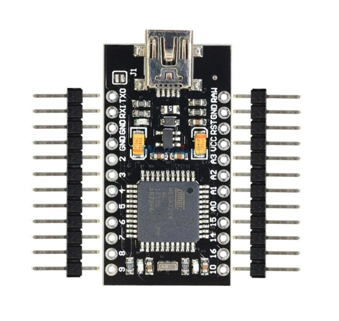
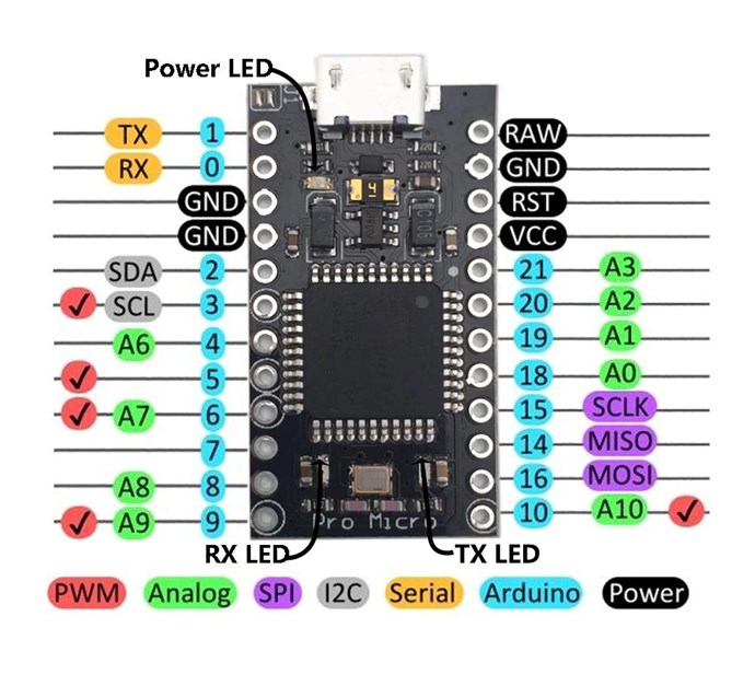
Of course, the Mega has different Pin Outs. This Code is very adaptable! Please post here if you need help changing the Code to suit your Microcontroller.
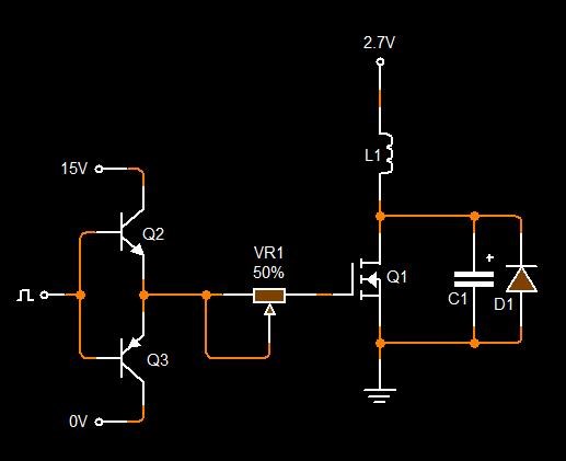
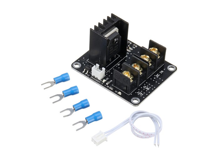
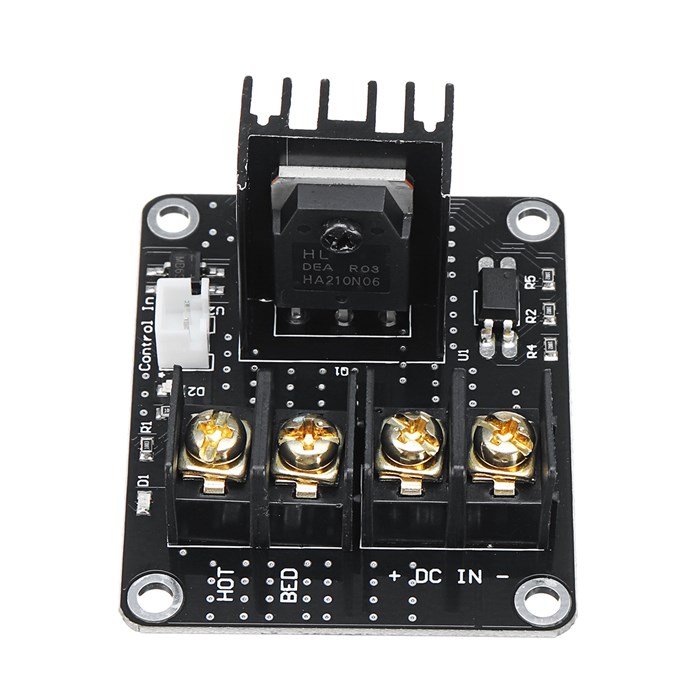
PWM can be used to drive any Mosfet, Transistor, SCR, Triac, Relay and many more Switching Options! For about $6.00 one of these can be purchased: MOSFET High Power
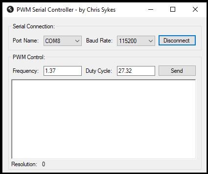
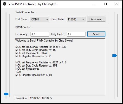
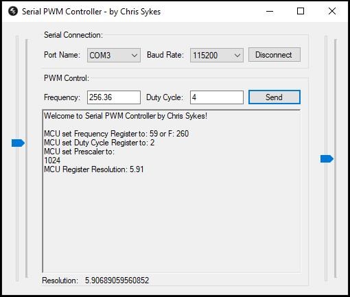
Of course, some sort of interface to update your Microsontroller can be used, USB Serial, WiFi or anything like this can be used to change the Frequency and Duty Cycle, but more Code will be required.
For less than $10.00 this is a great option to get started!
@Zanzal and other Dev's, please feel free to add Code or suggestions to improve the Code.
Best wishes, stay safe and well My Friends,
Chris