Hello el_fuego333,
I would really appreciate posting a Circuit Diagram with your test points clearly marked:
Please read our Measurements Thread, this is important to get a grasp of what it is, that we are doing, and how to correctly measure these machines.
Lets start at the start:
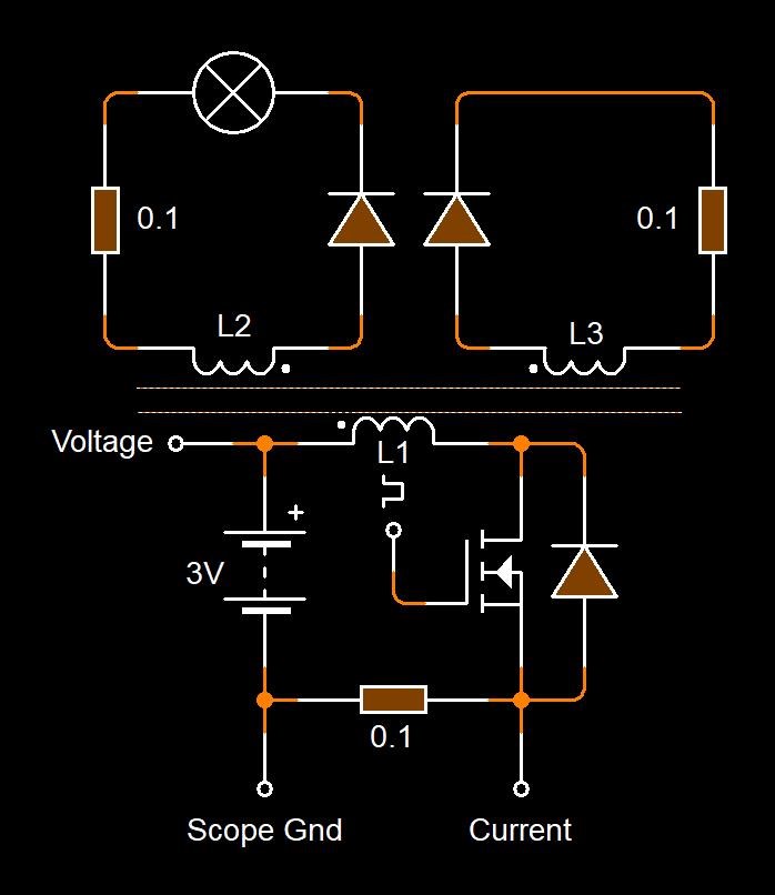
I would like to show You my input from the battery to the coils.I would like to know Your opinion how to calculate the input power from the battery. CH1 - yellow - is a voltage across the input terminals to the "MrPreva style" coils. CH2 - blue - is the current into coils.
Key Word here is "Battery", of course, any Battery is only ever capable of delivering DC to its source, so current and voltage can only ever have a single specific Polarity from the Battery, Positive and Negative, the Batter can not deliver anything else! This means, anything else you see on the Input Measurement, must, and can only be, coming from the DUT, Device Under Test itself.
This means, if your measurement procedures are correct, and you see Negative Voltages and or Currents, then these must be coming from the DUT!
You can read: The Input Coil for further information on this topic! What you have is a Non-Linear Load and you need to account for this in your Measurements as we have laid out in the threads mentioned.
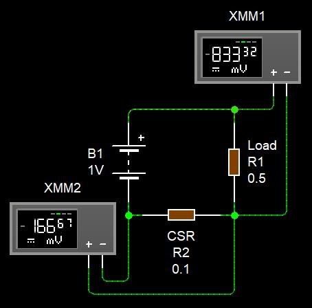
You need to take into account the numbers, for Negative Power, you need Positive Voltage and Negative Current. So 12.0V * -1.0A = -12.0W Instantaneous Power.
50% duty cycle. Pulse starts with 8.95V and current rises. After the pulse there is a very powerfull spike -129V with real current back to the battery. For the total consumed current from the battery we can not use Vrms, because there is backward current back to the battery with is calculated into Vrms. So lets look on Vavg +32mV which is the same reading as my multimeter shows. The same principle should be used for the main voltage on CH1 - Vavg shows -995mV... LED is flashing strongly.
That's correct, you must NOT use RMS, because a Battery is a DC only device and if you have Alternating Currents, this is NOT coming from your Battery!
The fact that you are getting +32mV and -995mV respectively shows to me, that there is an issue somewhere. One of the numbers should be Battery VoltageAverage ( 12.4 VoltsAvg ) for example. So your voltages are way to low, giving me some indication there is a problem somewhere. Now, if I have got this wrong, and these numbers should be +32mA and -995mA respectively, you need to make this clearer.
Looking at your scope shot, the big Negative voltages, do not mean Negative Power, if you do the math, -129V * -1.0A = +129Watts, Positive Power. For Current to flow Backwards, you need a Positive Voltage, greater than the Battery Voltage, and then a Negative Current will flow backwards.
If it would work as a standard flyback transformer or joule thief the strong spike to the battery would not be there. I know the correct way here is to use data analysis. But what is the correct way to calculate the power from data in this case ? It is not so simple by multiplying each row of the datafile and by the + or - mark of the result decide if it is a "from battery power" or oposite.
Instantaneous Power Measurements from the scope are sufficient, if you have enough cycles on the screen, and yes ideally a Waveform Analysis approach would be nice, but you will get an idea using Instantaneous Power Measurements. Don't confuse Positive Power with Negative Power, and Remember, what's above the Zero Graticule Line and what's below the Zero Graticule Line, is Power, so the Instantaneous Power at Time t, is what the scope calculates: V x I.
There is a situation when during the cycle where the voltage is positive, but less than "offline" battery voltage and the current is flowing from the coils to battery, also than the voltage on the input terminals turn oposite and current is flowing the same way - into battery. And the multiplication result of values in such cases has different +- marks and both cases is the flow to the battery. So, whats Your opinion? How to calculate approximal and exact power consumption in this case?
Yes, its possible, you can check the standing Voltage of the battery, rest the battery for One Hour, measure the voltage, then run your machine for Two Hours, let the battery rest for an hour, and then measure the voltage and see what the difference is.
Use a 1AH battery or smaller, if you use a 7AH or bigger, you wont get an idea of what's going on!
Reading your post, you really don't want to reverse the Battery's Voltage, the Terminals should not change Polarity, the same polarity should be maintained, so a Positive Terminal should stay positive and the Negative Terminal should stay Negative, you will damage the battery and or yourself, the Battery could Explode. I don't recommend doing this, its dangerous.
To properly "Charge" the Battery, the Positive Voltage Terminal should see 2-3 Volts Higher that the Battery's Rated Voltage, so the Positive Terminal always stays Positive. Again, the idea, to properly Charge the Battery, is to keep the Positive Terminal, Positive, about 2 to 3 Volts above the rated supply Voltage. -V * -A is still +watts, not negative!
I was reading the forum and I found You wrote, that there is no extra energy on mr preva circuit because there is a voltage drop. If You place the resistors like MrPreva showed, Yes, there is a volage drop.
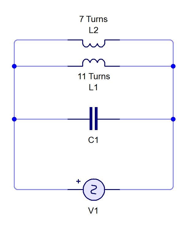
There is more to it than this. Study the Common Mode Choke, and you will see why there is a Voltage Drop. This is too complex for one post.
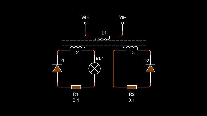
The MrPreva Experiment, by itself, is not Aboveunity. The Circuit:
Measuring either side of the Coils, gives you the Capacitor Voltage at Resonance, the Load, of which there is none, can not be measured, unless one adds a Load, and there is only one real position to add a Load, which is in between the two Coils, at one of the Nodes, if one does this, then you will see a Voltage drop, which is significant.
This is really basic Electrical Engineering and to be honest is not even really a topic for this forum. Its not even something we should discuss in detail, a quick sentence is all that is required to cover this.
LCR Resonance by itself is not Above Unity!
The Mr Preva Experiment by itself is also not Above Unity!
In saying this, it is possible to make an arrangement with extra Coils and Configurations, go Above Unity! It is possible you have achieved Above Unity, because I don't know the entire configuration. So please don't get disheartened by my observations.
Taking this seriously requires not allowing yourself to be fooled by yourself or by others.
If you are really interested in Above Unity, then you need to read and study the pages we have given you, and work on Asymmetrical Electromagnetic Induction.
Please go and read the threads I have shared with you, you will get a bit more of an idea what I am trying to point out.
Best Wishes,
Chris