My Friends,
We have covered this many times, in many threads: Negative Power
You must understand and observe Negative Power, to be able to achieve Free Energy Machines!
First, you will not find this topic covered anywhere! Its a Forbidden Subject! Taboo! Negative Power is NOT Negative Energy! I believe many have confused this very simple subject however!
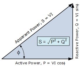
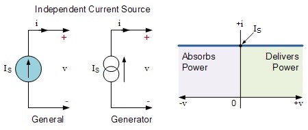
The easiest way to understand Negative Power, it if one of the Values you are using is Negative! In the following Argand Diagram, you can see this a little better:
Four Quadrant Power Flow Argand Diagram
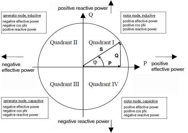
The Four Quadrants represent a Two Dimensional Axis of a Three Dimensional problem, Power in Time. Each Quadrant has a Meaning, marked, Capacitive or Inductive, Positive, and Negative! The Centre Cross is meant to represent Zero, which is not marked as such! The drawn Power Triangles does represent this however.
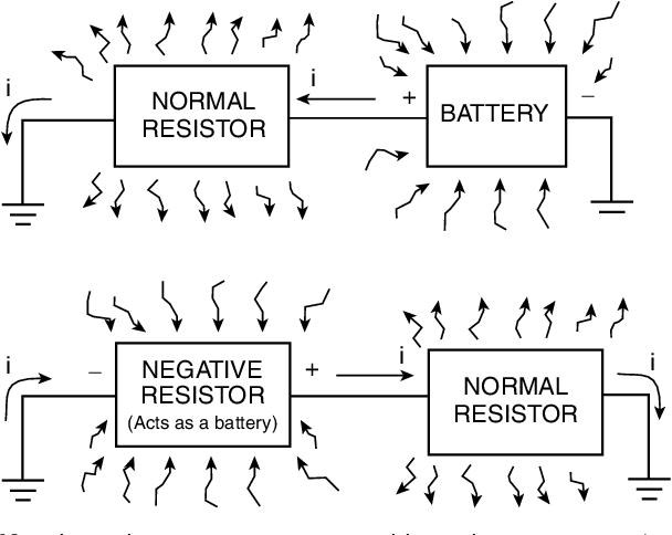
Focusing on the term: "Negative Effective Power" gives us a clue as to what is required to solve for this Scientifically Sparse subject!
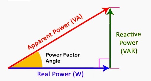
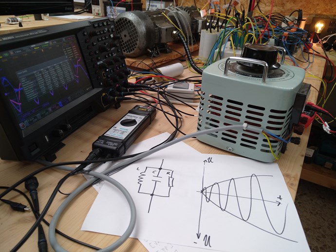
Here is a very basic, poorly drawn, image that shows a Phase Angle:
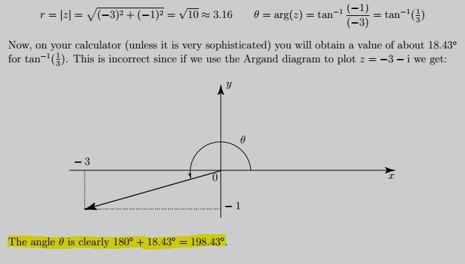
Ref: Argand Diagram - Quadrants help
If you have not yet already worked this out, the Applied Voltage is assumes Positive, and we have a Phase Angle difference to this Voltage. Here we see the Phase Angle θ is 198.43 Degrees. Is this correct? We have 360 Degrees in a full Rotation and we see just over one half Rotation don't we!
When you measure the argument of a complex number you go counterclockwise from the x-axis.
NOTE: The Y Axis is Imaginary. The X Axis is Real. This is Number Wise!
Power Factor
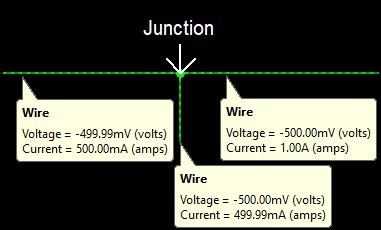
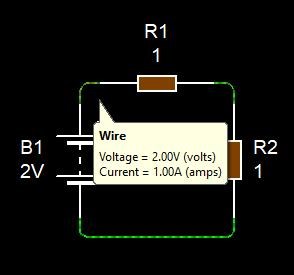
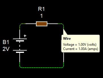
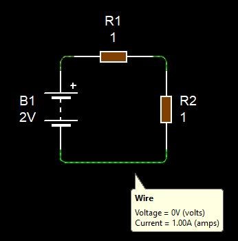
The very simple application of Power Factors also show you further how this works! In our Aboveunity.com Calculator:
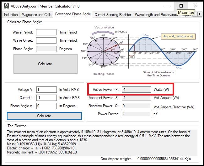
Here you see Mathematically: 1 x -1 = -1. Very simple Math to show you, the Volumetric Quantity of Power can be Negative!
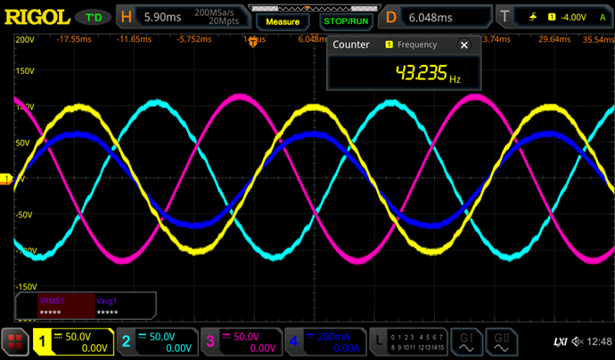
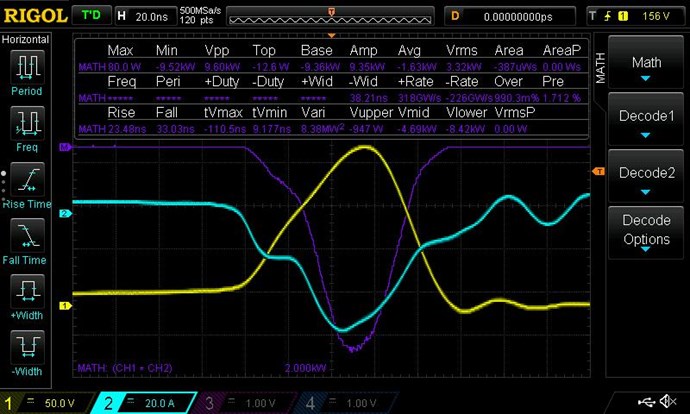
Here is an example:
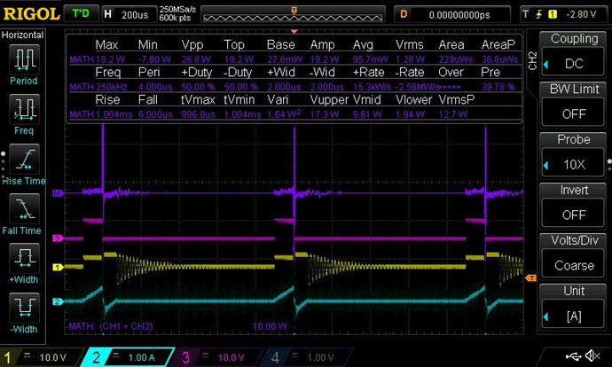
Where:
- Purple Trace is the Math, showing Positive and Negative Power.
- Pink Trace is the Gate Signal to the Mosfet.
- Yellow is the Input Voltage.
- Teal Trace is the Input Current, both Positive and Negative.
I must apologise, I have better examples of this, but do not wish to confuse everyone. This example is sufficient to show what I am talking about.
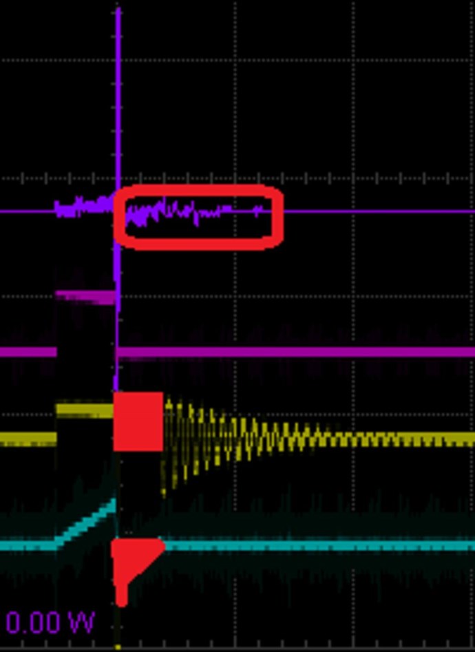
Again, marked in Red, Positive Voltage and Negative Current, you have Negative Power. Not Negative Energy, Negative Power, I hope people do not confuse this as I believe people have in the past.
I hope this helps others when doing experiments, knowing what to look for is very important!
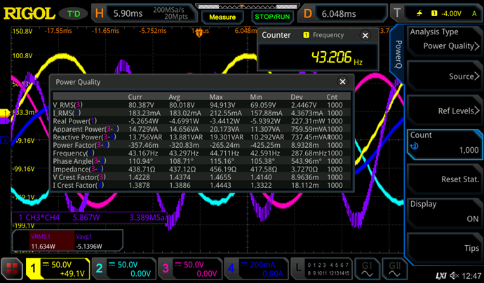
Remember: This is the very reason you can NOT Use RMS Measurements on the Input! See Measurements Thread and see the above Figures:
- Average: 95.7 mW
- RMS: 1.28 W
A Huge error here! 1.28 - 0.095 = 1.185 Watts. 13.474 times!
A MASSIVE: 92.5234375% Drop because I have more Power Coming Back to the Input!
RMS is totally Wrong! Remember, your Zero Graticule Line is very important:
- above: Positive
- below: Negative
Its worth noting, there is 1.28 Watts in the System.
Meaning, the Power in Purple Above the Zero Graticule Line:
Is more than the Math in Purple Below the Zero Graticule line:

By: 0.095 Watts.
We need to understand Negative Power! It's Important! It is how Free Energy Machines Work!
Another example:
Why does the Input drop 68% when Under Load?
Fill this thread with your comments! It will be interesting to see what we can come up with here!
Best Wishes,
Chris


 )
)