Plasmonic's Partnered Output Coil Replication

  • 355 Views
  • Last Post 22 October 2023
Plasmonic posted this 15 October 2023

Hello Everyone,

First I want to thank Chris for sharing his work and his advice, it is sincerely appreciated, thank you.

I have been working on this setup for a little while now to understand how it works.  I'm not yet at the stage of taking measurements or optimizations but rather trying to get the waveform(s) and ensure everything is working while I learn the fundamentals.

So I would like to share where I currently am to be sure I stay on track, and with that, any criticisms or suggestions are more than welcome and appreciated.


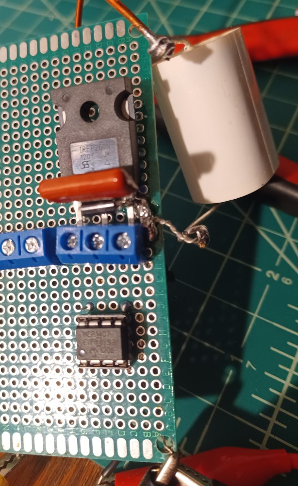
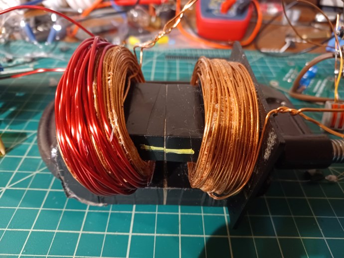
This is my current setup, my primary is 45 turns of #15, both POCs are 180 turns of #18 and are 284mH and 281mH for POC1 and 2 respectively.

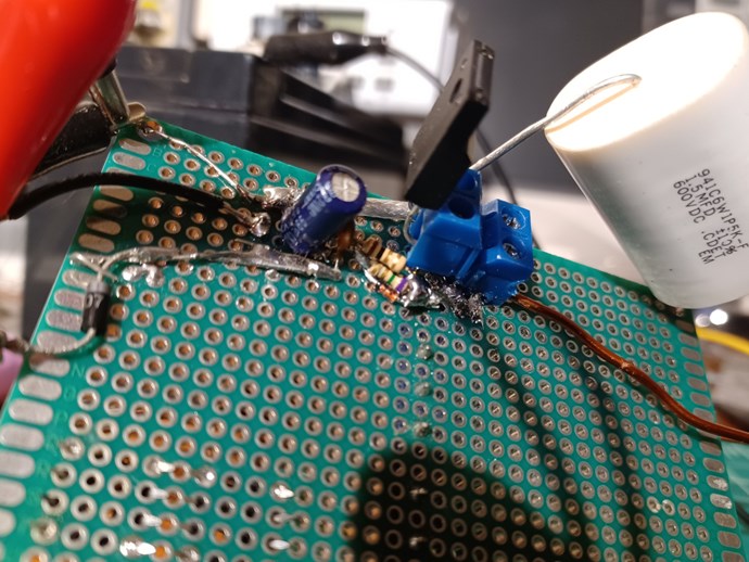
My coil and output circuit: setup

Plasmonic's coils and output circuit

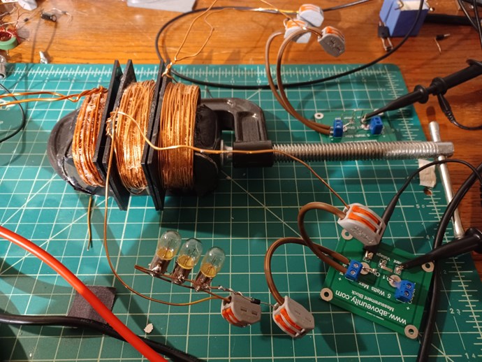
POC1 is loaded by 3 flashlight bulbs in parallel making 1.7ohms when cold.  In the following trace the bulbs are not illuminated so I assume it should still be near that 1.7ohm value.

POC2 is a short circuit thru the diode and .1 ohm current sense resistor.


Operating frequency is 4,240hz @ 46% duty cycle.

Power input is 4.6V and 170mA


I made a small mistake with the POC 1 yellow trace, the scope is set to 1x by mistake but my probe was 10x.  The purple trace is a 100x probe and without the ground connected.  I do not trust its numbers, I was just using it to see the waveforms together the best I knew how.

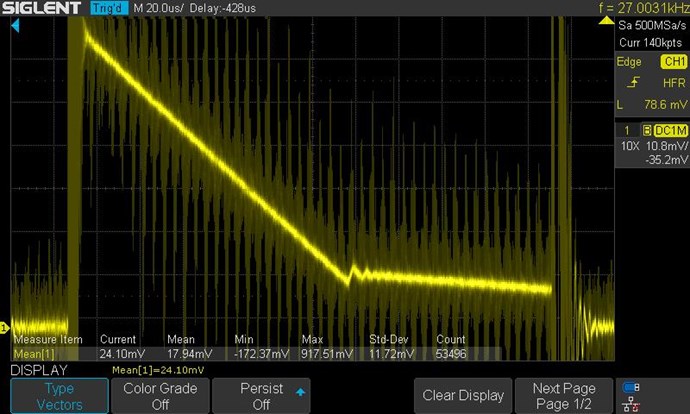
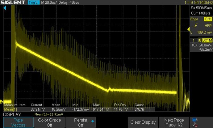
Scope trace of my current progress:
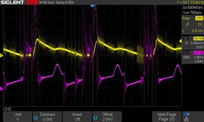
Yellow POC1 Purple POC2

Yellow is POC 1

Purple is POC 2

I'm not sure how to interpret my POC2 (purple) trace but one thing I think is on the down slope of POC1 there looks to be a positive feedback that is coming from the POC2 waveform and the inverted ramp seems to be changing the rate of decrease in current of POC1.

I'll add that my driver has a 279V TVS diode and 100nF capacitor across the drain and source of my mosfet to prevent breakdown of the mosfet and it has fixed my issue of burning them up.


I'm still trying to connect the dots and it's been a long 3 days so I think that's all I have for now.  I am looking forward to progress though!


Be Well,

Matt

Order By: Standard | Newest | Votes
Chris posted this 15 October 2023

Hey Matt,

Thanks for sharing!

Can you please post an image of your Input/Drive Circuitry?

There is a fair bit of visible noise in there, so maybe we can look to that first, try to improve that, and the rest will look better.

It is best to have your Input on top of POCOne also, you get a much better coupling, you can wind your Input over both POCOne and also POCTwo if you wish! That way you get a better Isolation. Also twisting your wires together can give you a dead short if the insulation gives...

Also, 945KHz is way too high, go way back down to around 3KHz and a 10% Duty Cycle. Its much easier to work at low frequency, later we can increase if you need to.

Your waveform, other than the noise, is pretty good, you're on the way!

Best Wishes,

   Chris

Plasmonic posted this 15 October 2023

Hey Chris,

While reading what you said I realized I may have an idea of where most of the noise is from and it's probably my PSU, it hisses at low amps but it's the best one I got atm, I'll for sure look into it and see what I can do though.  The driver looks like crap but it keeps quite a nice waveform when driving the coil.

Rising edge

Falling edge

plasmonic driver top

plasmonic driver bottom


Also, 945KHz is way too high, go way back down to around 3KHz and a 10% Duty Cycle. Its much easier to work at low frequency, later we can increase if you need to.

My driving frequency is only 4.2KHz my scope is reading some part of the wave (noise) on the frequency counter.  The noise is bad for sure, I should point out the scope mimics a phosphor screen scope so some of those spikes are from previous cycles.  So inside my switching waveform you can kinda see it fluctuates a little if you look closely at the falling edge trace.

I will go back and look at a little lower frequency now that I have both probes on it, I did see something similar to what I have now but it had a very long flat between the 2 sections of down slopes and I have not seen it before so it just confused me at that time.


It is best to have your Input on top of POCOne also, you get a much better coupling, you can wind your Input over both POCOne and also POCTwo if you wish! That way you get a better Isolation.

I can't fit any more turns over the coils they just about take up all the space between the core legs.  The coils are glued so if I break up the bobbins I think I can manage to get one of the coils to slide around the bend of the core so I can fill the space from that direction with the coil 90 degrees from where it is.  Do you think the distance between POC1 and 2 that would come from that change would negate the benefit?  Otherwise I have to rewind the coils in some way.


Oh and yeaaah, I'll have to fix the wire twist...  I just did it to keep everything held together while I'm fumbling around with that precariously built circuit but still, probably not my best idea. lol

Your waveform, other than the noise, is pretty good, you're on the way!

Also thank you! I'll keep at it and get on with the fixes!

Be Well,

Matt

Chris posted this 15 October 2023

Good Job Matt,

Mosfet Hard Switching has been covered on this forum many times, and removing those capacitors is a good idea!

Remember your Input is only a catalyst, this is just an excitation, so your Partnered Output Coils can be bought into Resonance. However, don't be scared to use a little bit of Power on the Input!

Have a bit more of a read of the help section: Builders Guide to Aboveunity Machines

Check out our recommendations for Mosfet Switching, and Partnered Output Coil Resonance.

I can see you have done a lot of research already, and I am helping you because I can see you are working hard to help yourself, as many others here on this forum are, and I appreciate all Genuine members! Sometimes I get frustrated and a bit cranky, I do apologise for this, I try very hard to keep the Genuine safe from the Damn Troll Scum Suckers!

The Greater in Magnitude of the Magnetic Fields, the Greater the Output Power, its a EM Pressure we are dealing with here.

Best Wishes,

   Chris

Plasmonic posted this 17 October 2023

Thank you Chris,

Just a small update.

I managed to get a new primary around the secondary and was able to get it somewhat back into position so I could vary the primary to secondary distance.  It seems to run best with some distance between them rather than closer to one another.  It's a small difference but it is noticeable.  The new test primary is 13 turns of #14 over POC 1

I also removed the capacitor across the drain-source pins of the mosfet.  It seems to be handling it okay but it's not quite as resilient as it was yet so I'm still looking into it so I can increase the power input.

I also need to find a new load that works for POC1 since I can push it till the bulbs burn out, I lost one of the 3 in the last test.  A 12V automotive lamp, (GE 1156) doesn't seem to work as well, I get the waveform but I cant push it into incandescence and it seems to weigh down the circuit too much to get any appreciable voltage drop across the sense resistor. 

Plasmonic, new primary test


2500KHz @ 8% duty cycle

Plasmonic, POC1 scope with low impedance primary
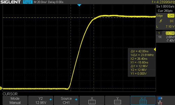
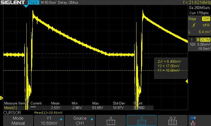
.  The cursor lines can be ignored, I just forgot to turn them off.
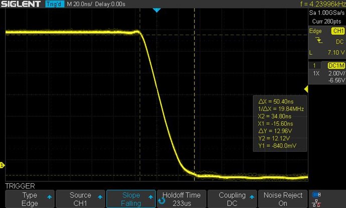
POC2 looks nearly the same but lower amplitude, still just the current sense resistor and diode in it's circuit.

For some reason the flat at the bottom of the ramp never quite reaches the zero line even at a much lower frequency and a lower duty cycle to keep the pulse short.  I'm still digesting what's going on here as it's got me a little puzzled. So I'm going to go back and do some more reading in the builders guide while I try to figure things out.

Be Well,

Matt

Chris posted this 17 October 2023

Hey Matt,

Looking good mate! Well done!

Peak Voltage, the Amplitude at which your Coils get to, is a function of how much Power Output can be obtained. In other words, Increasing the Amplitude, increases the Output Power.

Turn your Input up some, and study intently, you're on the right track! Nice straight lines there! Don't change anything, keep it all the same! Study and understand what you have.

Can you explain where the Voltage on POCTwo comes from?

See what I mean, here in lays the principle of the machine, its very simple, and once understood, its easier to Scale up.

Good Job Mate!!! Well done!

Best Wishes,

   Chris

  • Liked by
  • Plasmonic
  • Augenblick
Plasmonic posted this 18 October 2023

Hey Chris,

Can you explain where the Voltage on POCTwo comes from?

I'm not certain because my measurements are still really basic and one at a time so I don't destroy any of my equipment while I get used to the scope.  What I think I see though is that there seems to be no significant induction happening from the Primary into POC1 but I don't really trust my assumption, I'm probably missing something.

With that said, what it looks like so far to me is all of the induction occurs when the switch opens and you have the very steep rise on POC1 from the zero line.  POC2 seems to have the same situation at the same time.  So I'm not sure and do not want to mislead but so far it looks like an induction and (CEMF?) induction occurring between POC1 and POC2 from the collapsing Primary.


I've been observing some of the behavior of what it likes and doesn't trying to get my power input up and my output voltage up so I decided to try charging some batteries with it.  No efficiency measurements but I have found I can get what look like very good waveforms, I have tried at 12V and 36V with batteries in series.

No specific order or details but these were the waveforms during the battery testing.  Around 3400Hz

Plasmonic, battery charging output

Plasmonic, battery charging output 2

One thing I do know for sure coming out of this post is that my Mosfet held up much better with these tests, able to go above 20V and 1A.  The highest power I noted is 24W input so far.

Be Well,

Matt

Chris posted this 18 October 2023

Hey Matt,

Thanks for sharing your efforts!

Double Check, using the Right Hand Grip Rule and Conventional Current, that all Coils have the correct Polarity, from here, it looks like you do, but worth checking anyway.


Polarity should be:

  • POCOne Opposes your Input Coil.
  • POCTwo Opposes POCOne.
  • POCTwo Assists your Input Coil.


Of course, in a Conventional Transformer, any Assistance your Input Coil were to receive, would increase the Efficiency of the Transformer. So, if the Conventional Transformer were to be 85% Efficient, which is pretty normal, and your Input Coil gets an assist of 10%, then immediately, you will see Efficiency go up to: 95%, an Increase in Efficiency because of the Assist!

The more Assist you achieve on POCTwo, the more Power Output you get, which can very easily go Above Unity!

Try putting a basic Switch in your POCTwo Circuit, and use the switch to show this on your Input Circuit, the Current on the Input should Drop with POCTwo on, which is normal for Us, but totally Un-Conventional in Standard Electrical Engineering! Because no one in EE has gone this far.

Very simple experiments like this can sometimes yield the most surprising results, there is lots to learn here Matt!

Best Wishes,

   Chris

Plasmonic posted this 22 October 2023

Hey Everyone,

I have been trying anything I can think of to get the current reduction effect when connecting POC2 and I cannot seem to get it with my current setup.  I have seen it before under certain conditions but I dont think I had the linear decay in current from the POC coils whenever I witnessed it.


My primary is wound over POC1, both coils are wound in the same direction with respect to the core, making the POC1 output 180 degrees out of phase so the diode is connected as thus to allow current during power input.

I have tried POC2 in both orientations, wound the same as Primary and POC1 as well as flipped and flipping the diode to match the phase change, it's oriented to only allow current that is not from the primary induction during the input phase.  As you can see I do get waveforms of linear decay but my POC2 tends to increase the current rather than decrease the current.


I'm going to keep trying, maybe revert back to my old primary until I get the effect again.

Be Well,

Matt

Chris posted this 22 October 2023

Hey Matt,

Get your Currents up, on a 21 Watt Lamp, rated for 12V, this will give you a Current of: 1.75, and if each Partnered Output Coil, has this Current, or there about's, it is much easier to see the assistive effect we have all shown for so long now.

Wistiti nailed it very early on:


Its very easy, like I said, POCOne Opposes your Input Coil, POCTwo Opposes POCOne, but at the same time it assists your Input Coil, there is no other way.

This Asymmetry is where we see the gain come from.

Asymmetry is the key to understanding this very simple technology.

Best Wishes,

   Chris

We're Light Years Ahead!
Members Online:

No one online at the moment


What is a Scalar:

In physics, scalars are physical quantities that are unaffected by changes to a vector space basis. Scalars are often accompanied by units of measurement, as in "10 cm". Examples of scalar quantities are mass, distance, charge, volume, time, speed, and the magnitude of physical vectors in general.

You need to forget the Non-Sense that some spout with out knowing the actual Definition of the word Scalar! Some people talk absolute Bull Sh*t!

The pressure P in the formula P = pgh, pgh is a scalar that tells you the amount of this squashing force per unit area in a fluid.

A Scalar, having both direction and magnitude, can be anything! The Magnetic Field, a Charge moving, yet some Numb Nuts think it means Magic Science!

Message from God:

Hello my children. This is Yahweh, the one true Lord. You have found creation's secret. Now share it peacefully with the world.

Ref: Message from God written inside the Human Genome

God be in my head, and in my thinking.

God be in my eyes, and in my looking.

God be in my mouth, and in my speaking.

Oh, God be in my heart, and in my understanding.

Your Support:

More than anything else, your contributions to this forum are most important! We are trying to actively get all visitors involved, but we do only have a few main contributors, which are very much appreciated! If you would like to see more pages with more detailed experiments and answers, perhaps a contribution of another type maybe possible:

PayPal De-Platformed me!

They REFUSE to tell me why!

We now use Wise!

Donate
Use E-Mail: Chris at aboveunity.com

The content I am sharing is not only unique, but is changing the world as we know it! Please Support Us!

Thank You So Much!

Weeks High Earners:
The great Nikola Tesla:

Ere many generations pass, our machinery will be driven by a power obtainable at any point of the universe. This idea is not novel. Men have been led to it long ago by instinct or reason. It has been expressed in many ways, and in many places, in the history of old and new. We find it in the delightful myth of Antheus, who drives power from the earth; we find it among the subtle speculations of one of your splendid mathematicians, and in many hints and statements of thinkers of the present time. Throughout space there is energy. Is this energy static or kinetic? If static, our hopes are in vain; if kinetic - and this we know it is for certain - then it is a mere question of time when men will succeed in attaching their machinery to the very wheelwork of nature.

Experiments With Alternate Currents Of High Potential And High Frequency (February 1892).

Close