Pulse Charger with opposing coils

  • 4.1K Views
  • Last Post 31 October 2020
baerndorfer posted this 28 May 2020

While trying to understand more of this opposing coils thing i build a pulse charger.

this is how the circuit looks actually..

i build many of these small coils from stuff laying around - they all work but the frequency is different.

when i have 2 toroids with same dimensions and properties i will do one with the ordinary winding and the other with opposing coils (same wire mass). think then i should be able to measure a difference.

btw this charging circuit works brillant on lead acid or other 'loads'.

regards!

Order By: Standard | Newest | Votes
Chris posted this 28 May 2020

@Baerndorfer - Nice work! Beautiful Build! Thank You for sharing!

@All members, I would ask your input to help Baerndorfer with his Opposing Coils. He and I have had a few private messages, and he asked for input, to guide his Coil Project, to where is can be seen to do things not described in the average textbook. Baerndorfer please correct me if I am wrong! And I got the wrong end of the stick.

@CD, what are your thoughts, I would be extremely happy for the community to be seen coming together to help other members along!

Initially, the circuit is ideal as a start, perhaps a few more diodes? Think of, and treat each Coil as a Source, a Battery. Each having polarity, a source of Voltage and also Current, where Magnetic Fields can make your Coils come to life!

Looking forward to see what our Number One Community can share and do to help Baerndorfer.

Best wishes, stay safe and well My Friends,

   Chris

Vidura posted this 29 May 2020

Hey   baerndorfer, some suggestions if I may. Looking for excess energy we have to be aware that it is mandatory to interact with the Aether environment, a disturbance in the latter can cause an inflow of energy exceeding the input. We know that bringing the core material in the non linear region near saturation during a part of the cycle can cause such interaction. For example a very simple way is adding a static magnetic field offset with a permanent magnet, seeking the best working point by changing the distance to the core.

Another way is working with asymmetric inductance between input and output as Jagau has explained lately.

Hopefully this helps some.

Vidura


Wistiti posted this 29 May 2020

Hi Baerndorfer! Welcome aboard! Great nice build of the Re-emf charger you done.

I have build many of these charger and I also have to say they work really well!

In my experiment I have see that collecting the bemf of the primary coil lower the power output and effect of the poc. Try with and without the diode on the collector of your transistor while monitoring the output of you poc.

Also the polarity of the diode at the output of your poc is crucial. Try flipping the diode to seek the better output with a reduced input power.

Thanks for sharing your works!

L0stf0x posted this 29 May 2020

Baerndorfer, very nice setup!! Thank you for sharing!

It reminds me a similar setup... 

I can suggest one thing that worked in my setup, I maybe wrong, but it may help..

Static magnet on a closed toroid core I think will not give any profit. Its a fully close flux system.

Toroid is good to get and the last drop of flux back for use. But as Vidura suggests in a way its needed to trigger aether directly somehow. To make a "window" of communication with aether grid. 

I would try that... Do not use toroid.. Use a core from a flyback transformer, which is two equal peaces and makes easier to wind the coils. Then keep the one connection point of the two peaces in touch, the other to have an open (small) gap. Place an extra coil at the one exact end of the core. Connect the earth at the one side of the coil and leave completely open the other side.

(To make a good contact at the other side of the core connection, and not be inclined, you can add a thin iron washer at the one closed side and at the other side place a same height paper or plastic so to get the core straight)

Like that.. 


If you have time and want to test it try it. I had tested a similar setup before few years and I was getting very good results. I don't put my hand on fire for that but you can try it and see.. With this small gap you may open a window to aether, then I guess the static magnet can play a roll as well. So the gap leaves you with more options to try different things. Again I am not sure it will work, it is something I would try. I hope it will help you!

This is the video of my setup.. I used a combination of 3 cores... look the changes of the input current when I connect the earth to the open coil at the edge of the core (the other side of the coil is not connected anywhere), then when I disconnected it and then when I disconnect the load.


baerndorfer posted this 29 May 2020

hey cd_sharp!

i came across this ReEMF circuit - the guy in the video did a very good explanation on this.

thx for all of your tips!

Atti posted this 29 May 2020

Welcome baerndorfer.
I don't know what your intentions are with the layout you drew. I would add a few thoughts to the pulsed charge.
I just re-uploaded an older video 

thoughts: https://terszobraszat.hu/2-ingyenenergia/2-4-az-ingyenenergia-titkai/2-4-21-a-neogen-dinamo-bevezeto/2-4-23-bedini-fele-ssg-energizalo-bevezeto/2-4-23-4-ssg-kiserletek/2-4-23-4-1-pastor-kiserletei-a-hatartalan-toltovel/


Use it healthily.

Nagy Attila.

YoElMiCrO posted this 29 May 2020

Hello baerndorfer

Like everyone in this community we can contribute ideas to the experiments,
in order to improve their efficiency, even if possible AU.
From the circuit I can say that the power supply should be higher
voltage that the battery to charge at least in Vbe , approximately 0.7Vdc
for silicon transistors.
Also that it's a self-oscillating core saturation circuit and
like all they have defined all the parameters like frequencies and duty.
As Vidura and L0stf0 say the problem is the window to the energy medium
that maintains matter.
In what we can help we will surely do it.

Thank you in advance.

YoElMiCrO.

baerndorfer posted this 30 June 2020

after hours of reading through this big encyclopedia here i gave my base-circuit a little redesign.

as a result i have a working model where you can see how to extract energy without diminishing the source dipole.

regards and thanks for all your help.

*** PLEASE WATCH SUBTITLE ***


Chris posted this 30 June 2020

Hi Baerndorfer,

Apologies, some technical problems with My Flux Capacitor. Site has been down for a few hours now.

Fantastic work! Very nice, Thank You for sharing!

At this point, it can feel like there is no further to go, nothing more can be done, but breaking this down to whats going on there is a lot that can be done.

First, you have a huge achievement! As the load is placed on the Machine, the Input Power comes down as it should! So well done, again a huge achievement!

These machines work on the Interactions of Magnetic Fields. This means the more the Magnetic Field and the Faster the Magnetic Field can work together, the better.

From here, things like:

  1. Bigger Core, with a larger Cross Sectional Area CSA.
  2. Wire Gauge which is larger, 14 gauge or something like that.
  3. Sharper Input Pulse, into a lower Impedance.
  4. A Gap in the Core can sometimes help.
  5. Measure Core Saturation, if saturated or not.


Other things also, but these are the main ones. Well done Baerndorfer! You should be very proud!

Best wishes, stay safe and well My Friend,

   Chris


P.S: I am speculating a little, cant prove it yet, but I believe the Length of the Coils also have something to do with this also. Long Coils are less desirable, at least to a degree.


YoElMiCrO posted this 01 July 2020

Hi all.

@Chris.

I think like you, it is not a theory of length.
Since what is needed is an intense magnetic field
the inductors should grow in diameter and not in length.
If we look at this equation:
H = NI / Le.

N = Number of turns.
I = Current flowing through it.
Le = Length of the solenoid.

We will see that H increases with the number of turns and decreases
if the length increases.
This is why in electromagnetic cranes the electromagnet
it's almost flat.
That is why the great Nikola Tesla claims that his pancake-coil
it is the best coil there is.
If we go a little further and want to amplify E field
that is formed in said coil, we make it bifilar in inductive mode,
in this way we increase its layering action through
of the dielectric that the conductors that form it possess.
We are talking directly about Tesla's original Pancake Coil.


Thank you all in advance.

YoElMiCrO.


baerndorfer posted this 01 July 2020

yellow shows collector from transistor / blue is the POC

looks nice but should be improved !

regards and thx for your support

Chris posted this 01 July 2020

Hey Baerndorfer,

There must always be room for improvement, we must always think this way, but at the same time, you have a great achievement there! Be proud, many people have not gotten this far!

Well done, congratulations!

Best wishes, stay safe and well my Friend,

   Chris

Chris posted this 01 July 2020

My Friends,

YoElMiCrO's logic is sound! As always! Thank You YoElMiCrO!

Magnetic Fields as they interact together, are the catalyst for "Generating" Energy! The Stronger ( H ) and more Dense ( B ), the Magnetic Fields, the more Energy is Pumped! Remember what Floyd Sweet told us:

To free enough electrons to effect conversion would require magnetic forces approaching infinity.


Affecting Conversion, in other words, to change the atomic composition of the Atoms of the Copper, would require Magnetic Fields approaching Infinity, so, the more Magnetic Field, the more the Conversion!

This stuff is handy to know, and to directly experiment on in this manner.

Best wishes, stay safe and well My Friends,

   Chris

baerndorfer posted this 04 July 2020

vidura did some interesting measurements

OriginalSkywatcher posted this 08 July 2020

Hi all, this circuit works very well, I'm testing different setups using this method, though the difference is, in the past I've never used bucking coils.

Also, I found this short thread in another forum, interesting, he is talking about the need for an impedance or inductance mismatch in the bucking coils.

https://open-source-energy.org/?topic=1946.0

peace love light

OriginalSkywatcher posted this 12 July 2020

Hi all, decided to try using a small ferrite toroid.

The toroid is 1-1/4" diameter, using 24awg. 40 turns per partnered coil, one is wound CW, the other CCW.

Primary coil is 18awg. with 10 turns.

It is interesting, when the partnered coil L1 underneath the primary.

Is connected to the diodes, orientated to capture collapsing field, that coil does not give too much output.

Primary coil is at 6.7% on time.

However, when the other partnered output coil L2 is connected to a diode upon itself, or even short circuited, as chris has posted many diagrams of, the output increases dramatically, the input does increase as well.

When I connect that  L2 coil with diode, I can even hear some kind of static noise in my headphones, as if some higher voltage has just kicked in.

Anyway, interesting so far.

Oh, the primary circuit is also splitting the negative, re-emf charger style.

peace love light

Atti posted this 12 July 2020

OriginalSkywatcher.

Can you show us something more about that? Maybe a schematic drawing?


When I connect that  L2 coil with diode, I can even hear some kind of static noise in my headphones, as if some higher voltage has just kicked in.

Any more information on this?

Thanks.Atti

OriginalSkywatcher posted this 13 July 2020

Hi atti, I'll draw a basic schematic tomorrow for you, of the setup.

It is interesting though, when either partnered coil with diode, is connected to the 12 volt battery being charged, it barely has any output, based on the duty cycle settings at the moment.

Though as soon as either one of the other partnered coils is shorted or a diode placed across that coil, the output increases drastically.

My conclusion at the moment, is the partnered coils are inducing into each other, back and forth, just as chris has been telling us.

One partnered coil is acting as a primary, then the other acts a generator coil, then it pings back and forth, each coil switching rolls.

And the trick is, based on my reading of this web site and research.

Is to get the timing correct, so that the primary input is not affected and at the same time, we get this ping pong induction happening in the partnered output coils, that I think is occurring right now, in this setup.

peace love light 

Chris posted this 13 July 2020

Hey Sky,

My Friend, you are 100% spot on with your understanding! Very nice to see!

Best wishes, stay safe and well My Friend,

   Chris

OriginalSkywatcher posted this 13 July 2020

Hi all, Hi chris, thank you, Hope to learn more as I experiment further.

Hi atti, Don't think there is a need to draw a schematic at this time, as I can get similar effects, with just wiring the partnered output coils in series or parallel.

Though take note, with this setup, the POC coils can output power no matter how the POC  coils are wired in series and same for parallel.

Meaning, it still outputs with bucking and non-bucking wiring arrangement, though it is using the re-emf style setup, splitting the negatives, so to be sure, would have to wire it up in a more normal way.

peace love light

Chris posted this 14 July 2020

Hey Sky,

You are wise! It does not matter how Partnered Output Coils are connected!

@All reading,

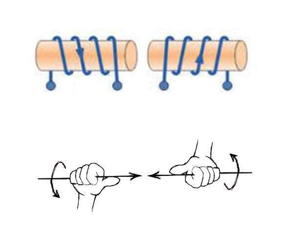
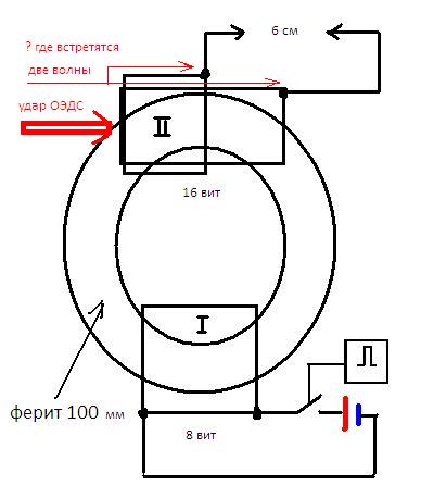
It is important how the Partnered Output Coils Interact together! L3 must see L2 as its Source! Or vice versa,either way around. If this does not occur, then its not working, but as Sky points out, it does not matter how the Coils are connected! How the Coils are connected will change the way the Driver acts however, Fighters ZPM is an example of this.

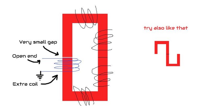
I shared this Image:

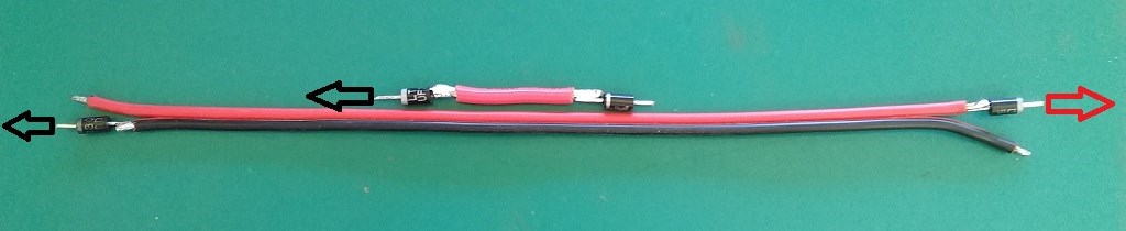
From Here: The Future is now, Energy, Space, its here now


The longer Red and Black wire represents the Partnered Output Coils. Each Current opposing!

Remember what Floyd Sweet told us:

Consider for a moment the construction of the triode which includes the bifilar coils located within the fields of the two conditioned magnets.

When the current in one half of the conductors in the coils (i.e., one of the bifilar elements in each coil) of the device is moving up, both the current and the magnetic field follow the right-hand rule.

The resultant motional E-field would be vertical to both and inwardly directed.

At the same time the current in the other half of the conductors in the coils is moving down and both the current and magnetic field follow the right-hand rule.

The resulting motional E-field is again vertical to both and inwardly directed.

Thus, the resultant field intensity is double the intensity attributable to either one of the set of coil conductors taken singularly.


Which, is, by definition, this:


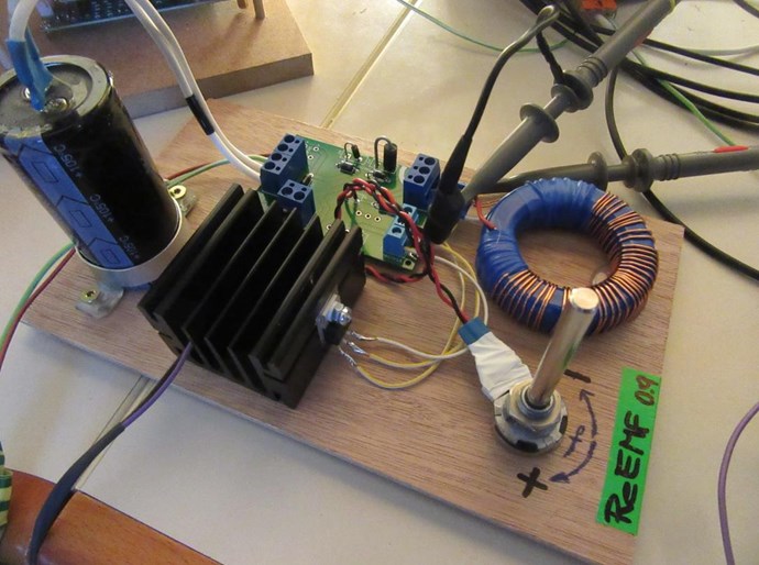
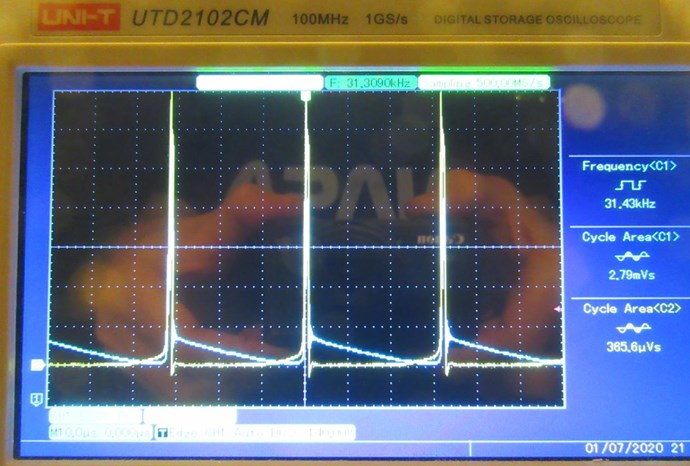
At the Frequency of Operation, the Partnered Output Coils, will "Generate" Energy, Amplifying Current, and Voltage depending on dΦ/dt, Faraday's Law of Electromagnetic Induction. 

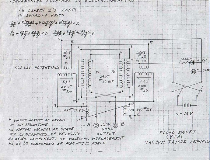
Skywatcher's interpretation is correct, as Floyd Sweet showed us, he had 2x sets of Coils, each set wired in Series to the other set, but both sets of Partnered Output Coils wired in Parallel:


It is amazing, the basic fundamental, elementary force of M.M.F, and its operation in such a simple Circuit!

Electrical Engineers spend all day trying to get rid of what they call Parasitic Inductance:


We want to capitalise on it! Its the Natural Law that is fundamentally connected to Newton's Law: For every Action there is an Equal and Opposite Reaction!

Best wishes, stay safe and well My Friend,

   Chris

alohalaoha posted this 02 September 2020

Le'ts speed up aboveunity.com above the speed of light.

Only for experimenters !

Chiksat:

"There was such, 6-7 years old experiment, accidentally had stumbled upon, but I had left to the side.

I will try to describe it again, briefly. I have wound 8-15 turns of PVC insulation wire 0.75 mm^2 primary on one side, ferite ring, weaving, in diameter, on the other side the secondary in one layer, 15-30 turns same wire. PVC insulation wire 0.75mm^2 , then a self-made meander generator with frequency and duty cycle tunable. I also don't remember what I have had assembled, does with NE555 or TL494, and the transistor was IRFP460 or IRF250 at the output. On the secondary, I had made a air gap of 1.5 mm between the ends. I had played with the frequency and duty cycle, and as i said, somewhere behind sound audio range, more than 16-20 KHz, the coil was stopped squeaking. I had heard a short sharp sound of a spark, (Psssss....), which immediately disappeared, since I was twisting the variable resistor. I had began to turn it back, and again (Pssss...) finally I had caught him slowly, MAYBE. caught resonance of the secondary. Then i had stretched the spark gap to the maximum distance, until the arc died out, it turned out to be 3 mm, then WITHOUT CHANGING THE GENERATOR FREQUENCY, I decided to change the winding direction of the secondary, for experiment, so to say, with different types of windings, I have wound the secondary again, cut it in half , wound with two wires, at once, and connected the beginning and end, according to Tesla pancake bifilar, turn on the signal generator, and on the arrester, there was a arc about 10mm in lenght. That is increased. Then I remove scondary, and I had rewound one half, and the second half, on top of the first half.I don't remember exactly, i think both windings were in the opposite direction, but since the diameter of the first was increased, the second half, those one wound upon the first has ended at the half of fist half. I had again started signal-generator AND AS THE TEACHER HAS FINGERED INTO THE SKY, I ALREADY HAD JUMPED TO THE SIDE, the whole coil had hissed and spattered with shiny blue sparks. I had took one end of the wire with isolated pliers and brought into vicinity of the other, the breakdown of SIX centimeters had occured. It turns out that the coil was self acceleratedo, self powering due to such opposite windings, most likely there was a wave resonance, (supperpositions of two opposite waves between two windings) had occued. Yes, the power supply was 12v either accumulator was, or a computer power supply unit. By the way, a breakdown of 5-6 cm is equal to 100-120 thousand volts, that is, 6000 volts per turn, that was pure CE (СЕ = aboveunity on Russian)."

Schematic of experiment


baerndorfer posted this 02 September 2020

hi cd_sharp,

Can you please clarify what makes this circuit show a fast rise time?

did you mean the switching-time from transistor? so this is not that fast. i'm still searching for faster ones which can handle higher voltages.

https://www.onsemi.com/pub/Collateral/BU406-D.PDF

maybe i did not get your question...

regards

Wistiti posted this 03 September 2020

Hi guys!

One of the transistor I like to use is the npn 2sc3552. https://alltransistors.com/transistor.php?transistor=14884

But there must be better ones...

Hope it helps!

baerndorfer posted this 03 September 2020

like the specs from npn thx wistiti !

cd_sharp i think this is because of the trigger coil which i saw on the joule-thief circuit. the connection from trigger-coil-end goes to the beginning of the power-coil. this is how i like to connect the coils togetter on the input side. maybe this helps.

what i like to add is, that i always get the best results when the wire-length from the coils meets this 1/4wave thing. you noticed that in my drawing (90, 360, ...). what also works is when the coils have different lengths but same copper mass. maybe it works best if length and mass equals. i'm still building different coils and try to find out how it works and why.

regards!

baerndorfer posted this 04 September 2020

Can you be more specific on C2? What value is it?

i would say that C2 acts like a collector for the energy which comes from diode. i started with 1uF (MKP-X1, X2 works also) and noticed that when i raise the Farad on C2, then i can extract more energy from the aparatus (more light on the bulp and you can see it on oscilloscope [more Voltage]). actually i don't know how big it should/can be.

Atti posted this 24 October 2020


Hey beandorfer.


as a result i have a working model where you can see how to extract energy without diminishing the source dipole


Why did you delete the uploaded video? Is there a special reason? I wanted to find something back. You would put it back again. If not a big deal.

baerndorfer posted this 30 June 2020 )


baerndorfer posted this 24 October 2020

I was forced to set the video to 'private' because otherwise I get real problems. i will sent you the link as a private message. sorry for the confusion Atti.


thosewhocandothosewhocantteach posted this 28 October 2020

Hi,

I'm positive and hopeful about this POC tech and I hope it really supplies more energy than drawn from the power source. May I ask some questions?

What is causing the input to be 26W?

Do you know how much the output on the POC (lamp) is consuming?

Why is L2 wound like this?

I'm trying to understand the circuit.

Thanks and regards!


Chris posted this 28 October 2020

Hello Jcil.nl,

Welcome!

We have many pages for study and catch up, start here: Builders Guide to Aboveunity Machines

When you have read the existing help pages, your questions should mostly be answered. If not, then please feel free to ask any further questions.

Best wishes,

   Chris

thosewhocandothosewhocantteach posted this 29 October 2020

Hi Chris,

thanks for the welcome and the link! Would it be possible if you enabled secure http?

I finally do understand the POC, it is very simple. Just thinking out loud, 26W is dissipated because the coil is shorted and there is magnetic feedback to the primary, but why doesn't it drop much lower when it is opposed by the other POC coil when the lamp joins the circuit?

It must be figured out how the max load can be determined and how it relates to all parameters and ratio's. Mathematical and system models  can be made when it is understood and when there is a correct scientific method to determine AU.

Cheers =)

Chris posted this 30 October 2020

Hello Jcil.nl,

Yes, you are correct! One Partnered Output Coil always assists the Input, in other words: One Partnered Output Coil always has a Magnetic Field Vector in the Same, adding, direction as the Input Coil! Not opposing!

This means, your Input is substituted by One Output Coil, there is Extra Energy added to the System, in the same direction as the Input Magnetic Field Vector, Superposition is used Asymmetrically!

Max Load is a function of V and I and Machine Impedance. The same as a Conventional Electric "Generator", but with a few small differences.

SSL is expensive and to be honest, something I have looked at, but think is too expensive for the benefits. We don't have personal or any information that requires a SSL Tunnel, its all Public Domain and Open Source, a Secure Tunnel will be of little benefit.

I will check out the prices again soon and reevaluate again.

Best wishes,

   Chris

Chris posted this 31 October 2020

Hello Jcil.nl,

Thanks to Raivope, we have a SSL Solution and AboveUnity.com is now SSL Tunnel Secure. We will test and see how it goes! Please let be know if anyone has any problems!

Best wishes,

   Chris

We're Light Years Ahead!
Members Online:

No one online at the moment


What is a Scalar:

In physics, scalars are physical quantities that are unaffected by changes to a vector space basis. Scalars are often accompanied by units of measurement, as in "10 cm". Examples of scalar quantities are mass, distance, charge, volume, time, speed, and the magnitude of physical vectors in general.

You need to forget the Non-Sense that some spout with out knowing the actual Definition of the word Scalar! Some people talk absolute Bull Sh*t!

The pressure P in the formula P = pgh, pgh is a scalar that tells you the amount of this squashing force per unit area in a fluid.

A Scalar, having both direction and magnitude, can be anything! The Magnetic Field, a Charge moving, yet some Numb Nuts think it means Magic Science!

Message from God:

Hello my children. This is Yahweh, the one true Lord. You have found creation's secret. Now share it peacefully with the world.

Ref: Message from God written inside the Human Genome

God be in my head, and in my thinking.

God be in my eyes, and in my looking.

God be in my mouth, and in my speaking.

Oh, God be in my heart, and in my understanding.

Your Support:

More than anything else, your contributions to this forum are most important! We are trying to actively get all visitors involved, but we do only have a few main contributors, which are very much appreciated! If you would like to see more pages with more detailed experiments and answers, perhaps a contribution of another type maybe possible:

PayPal De-Platformed me!

They REFUSE to tell me why!

We now use Wise!

Donate
Use E-Mail: Chris at aboveunity.com

The content I am sharing is not only unique, but is changing the world as we know it! Please Support Us!

Thank You So Much!

Weeks High Earners:
The great Nikola Tesla:

Ere many generations pass, our machinery will be driven by a power obtainable at any point of the universe. This idea is not novel. Men have been led to it long ago by instinct or reason. It has been expressed in many ways, and in many places, in the history of old and new. We find it in the delightful myth of Antheus, who drives power from the earth; we find it among the subtle speculations of one of your splendid mathematicians, and in many hints and statements of thinkers of the present time. Throughout space there is energy. Is this energy static or kinetic? If static, our hopes are in vain; if kinetic - and this we know it is for certain - then it is a mere question of time when men will succeed in attaching their machinery to the very wheelwork of nature.

Experiments With Alternate Currents Of High Potential And High Frequency (February 1892).

Close