Munny
posted this
12 December 2020
- Last edited 12 December 2020
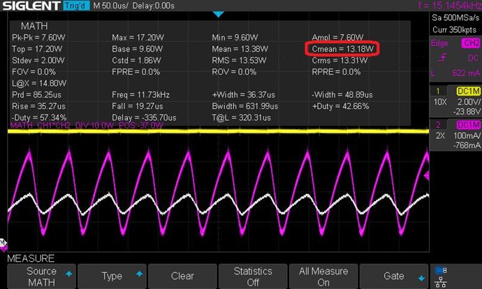
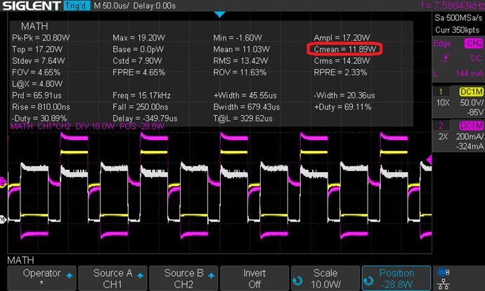
Just a precision, to have an average power you must take the column before mean, the Cmean that you have circled is for only one cycle, it is not the mean power.
It's my understanding, the reason one would "prefer" Cmean versus Mean is when there isn't an integer number of cycles presented on the oscilloscope's screen. Averaging in a partial (non-complete) cycle will skew the value. There is also the issue of how well your scope detects what an actual "cycle" is. One can override the scope's determination of a "cycle" by capturing the data into a file and manually manipulating all the data points, setting a boundary for the start and end of one complete cycle.
The alternative is to have many cycles presented on the screen and use the Mean value instead. Using this approach, the overwhelming number of samples will dwarf any small partial cycle. The possible issue here is the number of samples gathered--the resolution. Always keep in mind the images we see on the scope are actually just an array of data points linked together via graphics manipulation, either straight lines or curves. Regardless, the data points are only an approximation of what the actual waveform looks like. There could be all sorts of narrow spikes the scope does not detect due to its sampling resolution.
It's always good to have awareness about the tools we use. Modern oscilloscopes do a pretty good job of giving us insights into the signals we create, but they are not perfect. It would be nice if everyone had at their disposal a top-of-the-line Tektronix scope with high-end probes and calibration modules. Unfortunately this is not the reality, so I do understand, we use what we have.
As for using shunts, it's not a matter of luck. I saved my pennies for years to acquire a decent current probe. I don't expect anyone else to do the same. Just keep in mind when you use shunts, these components become a factor in their own right. If you use a different shunt on the input then you use on the output, you break consistency. If your scope does not have isolated grounds, you have to make absolutely certain the way you connect your probes does not introduce an artifact into your testing method. If you use a large value shunt, you can change the behavior of your DUT considerably. If you use a small value shunt, the voltage signal you measure across it can be right near the threshold of noise, rendering the values you obtain almost useless. My point in saying this is: It's always an engineering trade-off. You get something, but lose something else. You have to know what you can sacrifice and what you cannot.