Starting at the very start...

  • 446 Views
  • Last Post 11 December 2023
Marcus posted this 08 December 2023

Hello all,

My thread here will be very basic for all you experts out there, but I have no option but to start at the start. And then work my way 'upwards'. Please do feel free to correct me, tell me what I got wrong, and point me in the right direction. I will always try to describe what I aim to achieve, how I will set things up to do this, and my results together with my explanation of what I think I have seen.

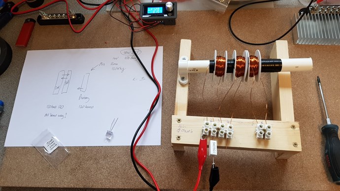
I have spent the last several weeks reviewing materials on this forum, and quietly built up a collection of equipment that has today allowed me to make a start, of sorts..

I have the following items:

  • Scope
  • 0-30VDC 10 amp PSU
  • Dual output PSU 2-12VAC and 0-24VDC
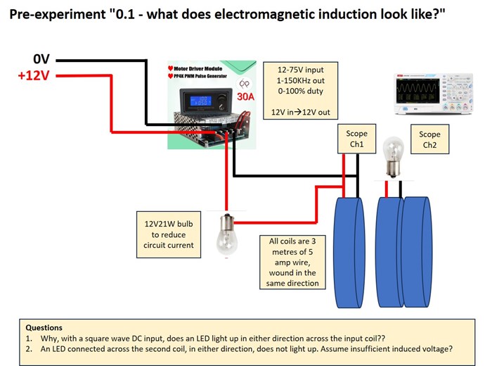
  • 'Square' wave PWM generator, 1-100% duty, 0-150KHz. This runs at 12V.
  • A couple of multimeters, one of which performs minor scope functions
  • Various connectors
  • Some megnet wire, and air coil bobbins.
  • All sorts of electrical detritus left over from building a car
  • Various diodes and LEDs
  • some Bourns 30W 0.1 CSRs which I will use to create my version of some 'measurement boards'.
  • etc

Shortly I will receive 2 pairs of C-Cores made of diffferent material, and some power resistors for limiting the current in my coil circuits.

My plan is to replicate some of your experiments to begin with, and learn what I need to learn.

My next post will post the results of my first pre-experiment.

Cheers, M.


Order By: Standard | Newest | Votes
Marcus posted this 08 December 2023

So, we start with pre-experiment "0.1 - what does electromagnetic induction look like?"

Purpose: to see on-scope the input and output waves, and to see what I can learn from that.

I put together the basic outline of the Tinman experiment as follows:

  • 12V PSU feeding a..
  • 12v PWM set to 500Hz, duty cycle 10% i think (I adjusted this to the minimum), feeding a..
  • 12V20W light bulb to reduce circuit power (my power resistors haven't arrived yet), feeding one of... (My input scope connections were set across this.)
  • the 3 air coils of an equal 3 metres of wire each, zero resistance per my meters,  arranged basically as per Tinman.
  • My secondary coil was connected to another 12V20W bulb as load. (My output scope connections were set across this)

My test used the input coil and only one of the output coils.

The scope showed me the following situation, blue IN, yellow OUT.

scope 1

I concluded that, for the first time, I was seeing electromagnetic induction taking place!!  What am I seeing? I think I see a smaller induced voltage in the second coil in opposition (reaction)  to the input voltage seen in the feed coil, when the voltage in the feed coil is rising. When the voltage decreases in the feed coil, I again see a smaller induced voltage in the second coil in opposition to the feed coil. In both cases, I see the time the second coil takes to 'fade' the voltage is greater than that seen in the feed coil. I decided to zoom in..

scope 2

From this I concluded that there is much more of a 'spike' when the transistor turns OFF the power than when it turns it on.

The final aspect of my pre-experiment involved turning round the feed coil:

scope 4

Now  I see that the induced voltage is in the same direction as the feed coil.

Other observations:

  • Increasing the distance between the 2 air coils reduces the induced voltage in the secondary, changes nothing in the feed coil.
  • The induced voltages are very much smaller than the feed voltages. Probably caused by a lack of turns?
  • Inserting a metal bar through the air coils slows things down, takes more time to dissipate in the secondary. Also changes the shape of the curves.
  • an LED connected across the feed coil lights up in both directions, against my expectations. I cannot understand this.
  • An LED connected across the second coil does not light up, I assume insufficient voltage to drive it?


A final trial involved leaving the load on the second coil, and testing the induced voltages on the 3rd coil. The results were the same but smaller induced voltages were seen, assumedly due to the increased distance.

I have further thinking to do now about what I have seen and learnt, but the next stage is to understand why LEDs work in both directions before proceeding with the experiment proper. There is something wrong with my circuit.

I look forward to comments, corrections, and guidance please!


Cheers, M.


  • Liked by
  • Chris
  • Augenblick
Chris posted this 08 December 2023

Hello and welcome Marcus!

Let me ask, Adam under a different name? Looks like the same work and the same approach?

Anyway, you're in good hands here, we will look after you! You have chosen to make the most advanced forum energy research site in the world, your home, so you chose well!

We will look after you!

I wanted to ask, what is the Circuit you have for the above experiment? You are quite right, it is the Change in Magnetic Flux that creates a Voltage in the Secondary, which is what you see, and the change can be Negative or Positive, the polarity of the Primary determines the polarity of the Secondary. Lenz's Law, always Opposite, thus the Negative Sign. Sign sensitive, and thus the Diodes attached to our Circuits will require this same polarity to be able to conduct in the specified direction.

Please Note: I think this line of research is Important and Valuable! You're doing good work! If you're Not Adam, then Adam is also doing good work! In my opinion, we have only had a small difference of Opinion here, which results in fundamental difference in Approach, that's why this is important! I like Adam, he is doing Valuable Work! As are you!

The Flux's do NOT Add here, because the Flux in the Primary is gone by the time there is a Voltage. So many people try to push this idea! The Sign, still Opposes as I have shown!

Ref: Polarity of a Generated E.M.F.


I have pointed out before, Diodes require a Voltage applied across them, in a Specific Direction to be able to conduct, and they can not conduct unless the Voltage is in the correct polarity.

Best Wishes,

   Chris

  • Liked by
  • Augenblick
Adam posted this 09 December 2023

Hello,

Nope, this is Adam not that. lol

Chris I think the Tin man device works exactly the way you say it does. 100%

I have never thought any different. I think everyone should be replicating that device. It's probably the most important device to test!

The normal Tin man device has two coils that have a diode/LED on each that face each other. Thus bucking!

I was just showing that I flipped one of the diodes/LED around so they both face the same direction. This gave me other effects. Its fun to play with but its not were the real power is just like I say in the video.

Please stick with the Tin man replica!

Marcus, Try changing the frequency and duty cycle. I found that the Tin man device would not give me good results unless I was at an EXACT frequency and duty cycle for the coils I was using! And I mean exact.

You just have to hunt around till you find it, just like all the other devices!

Chris has stated in the past you just have to fiddle with it a bit to get it to work.


The real Adam. lol

  • Liked by
  • Chris
  • Augenblick
Adam posted this 09 December 2023

Hello,

When you get the correct frequency and duty cycle both LEDs will light up!

If you don't hit the right Freq and duty then the primary is affecting one of the coils at the wrong time in a negative way and they will not buck.

This is very easy once you figure it out.

Once that happens you will be laughing at how easy it is!

That is why everyone should be replicating this device.

Adam.

  • Liked by
  • Chris
  • Augenblick
Chris posted this 09 December 2023

Hey Adam,

Once one knows how Partnered Output Coils works, it is easy to turn a few milliwatts Output to Real Watts Output!

The "Generated" E.M.F is a variable that is Load and Design Specific, so Both POCOne and POCTwo "Generate" each others Voltage!

The exact same principles apply all the way up to tens of Kilowatts!

This is so Important! This is so Simple! This is so Cheap!

Best Wishes,

   Chris

P.S: Wistiti did all these experiments well before Tinman ever did, as did I. We were not the first though!

  • Liked by
  • Augenblick
Adam posted this 09 December 2023

I agree, its just Tin man on a core with a few very minor modifications. lol 🤣

That is why everyone should be working on Tin man Replication until they get it to work!

Everything is in the videos Tin man's video and my replication.

Don't change anything wire size and # of turns use LEDs in the correct polarity.

Frequency will be close to the one given in the video then find the duty cycle.

That's it!

💡💡

👍

Adam.

  • Liked by
  • Augenblick
Marcus posted this 09 December 2023

Hello again,


Thank you for your comments, and no, I'm not Adam, but I will look at his experiments again shortly I think. Chris asked for my circuit, very simple, so here it is:

EXP01A

I have left his experiment alone today as I do not understand why my LED lights up in both directions across the input coil, with no other diodes in the circuit, despite my square DC wave oscilating between 0-12v. I have instead wound 3 coils each onto two sets of freshly arrived C cores today and played about with those. Since I do not understand what I am seeing and / or what I am seeing is not what I expected (!) I assume I have got something wrong. I will do it again tomorrow and report back whatever I find...

Cheers, M.


  • Liked by
  • Chris
  • Augenblick
Marcus posted this 10 December 2023

Good morning all,

I decided to have another go at my Tinman replication this morning, by starting completely afresh. I rewound my 3 coils (all clockwise) with 0.5mm wire with the suggested 120 turns each, set the 14VDC (later reduced to 12V) pulsing to 120khz and 15% duty. The setup appears as below.

tm rep1

At first I applied the input power directly, without the resistor you see in the photo. Under this circumstance I am very pleased to report that connecting a LED between (1) and (2) only works with the LED in one polarity! However, with the resistor in place, the same LED will light up whichever polarity you connect it between (1) and (2). I also tried using a 12V21W bulb in place of the resistor, and in this case the LED also lights up in both polarities! I am beginning to think that the resistor or bulb, each being a coil of sorts, is doing something...

However, never was I able to get an LED to light up between (3)+(4) or (5)+(6), in either polarity, so the experiment was an outright failure!

I am getting something very basic very wrong I think. Please could somebody maybe tell me what that is?

Cheers, M.

  • Liked by
  • Chris
  • Augenblick
Adam posted this 10 December 2023

Hello,

Don't use the resistor, The input pulse must be very fast!

Probably about  5% duty cycle.

You must keep hunting for the correct frequency and duty.

Start with small duty and higher volts then sweep through the frequency.

Don't make big jumps in frequency you may jump past the correct one!

Adam.

  • Liked by
  • Chris
  • Augenblick
Marcus posted this 10 December 2023

Hi Adam,

Thank you, will try that asap!


Cheers, M.

  • Liked by
  • Chris
  • Augenblick
Marcus posted this 10 December 2023

Hello Adam,

OK, quick tests just performed.

All at 12V, which is the minimum my square wave PWM machine can do. Current flow is plenty at that, and rises further if I increase V.

I tried:

2% duty 1Hz to 150KHz - No LEDs lit

5% duty 1Hz to 150KHz - No LED's lit

10% duty 1Hz to 150KHz - No LED's lit

20% duty 1Hz to 150KHz - no LED's lit and I abandoned this due to coil temperature.

When I increase frequency it is just turning a control, probably 2 minutes from 1Hz to 150KHz, maybe too fast? Not the slightest LED interest, and I connected 2 LED's for the test, 1 in each polarity, in each station. I tested again, abandoning the 3rd coil, and testing on the second (nearer) coil = no LEDs.

There is something fundamental wrong here I feel. Its probably the tester!!!


Cheers, M.


  • Liked by
  • Chris
  • Augenblick
Marcus posted this 10 December 2023

In another test, My LED's (big, clear 10mm LEDs) begin to show visible light at 2.45volts, when directly connected to the PSU.. Perhaps I am not getting this??

My other question is whether my PWM is behaving properly...but I can hear the coils vibrating at frequency...so not currently my chief suspect. It scopes out OK too.

What else could it be?


Cheers, M.

  • Liked by
  • Chris
  • Augenblick
Marcus posted this 10 December 2023

Right, so I increased the input voltage to 30V, and now both LED's are lit AT LAST. However, the furthest LED from the input coil would only light with a large allen key(!) inserted through the inside of the coils (which sit on a 25mm plastic tube)... I think the magnetic field is too weak to reach the furthest coil without it - lack of turns? 

Interestingly, with duty at 2%, there is not a lot of dependance on frequency, the furthest LED from the input coil lights from 5Hz to 175Hz then goes out, the nearest LED stays lit up to 26.5KHz then goes out.. Overall, things are not behaving as per the Tinman experiment, but having LED's lit via induction is a far less frustrating situation. I will pick up again in the morning. I still think there is a lot wrong.

Does this count as progress, lol? Basic-er basics for me I think. What have I achieved?


Cheers, M.

  • Liked by
  • Chris
  • Augenblick
Chris posted this 10 December 2023

Hey Marcus,

Any input frequency and duty will work, 10KHz at 10% Duty Cycle or 1KHz at 25% Duty Cycle, its only the change in Magnetic Field here that's important. You're only inducing a voltage in your Partnered Output Coil. Later on this does become more important.

Use the Conventional Current theory and the Right Hand Grip Rule to apply the correct Polarities. All THREE Magnetic Fields need to be arranged like so:


Keep trying, don't give up, once you get it right, you will know, and you wont forget, but study intently, because this is very important, its going to change the world, once those stupid idiots out there realise this is the only simple cheap path forward. Partnered Output Coils, using Dual Output Coils, is a technique most have never thought of, to bring about Asymmetrical Electromagnetic Induction, and therefore divers the Negative Input Forces, so your Input is no longer the Source of Power to the Machine, the Environment is, but so many have no idea how this works, its only through experiment and hard work we gain an understanding like this, Floyd Sweet gave me some understanding, but mostly the bench taught me what I know.

Don't give up, because you will look back one day and say, well that's was really easy! Why did my mind over complicate this very simple task?

Electromagnetic Induction really does Work! Its also Incomplete in Todays Scientific World, only here on My Forum, will you find the completed Asymmetrical Electromagnetic Induction Standards! No where else! I have given everyone the full and completed answer! No one can deny this fact!

Best Wishes,

   Chris

  • Liked by
  • Augenblick
Adam posted this 10 December 2023

Hi,

What I can tell you is when I replicate something I try to make it exactly the same.

If you don't then you really never know why it is not working. Right?

So lets see what is different.

Do your coils look like this?

With the Same shapes or sizes?

Tinman stated in his video the primary was half as tall and twice as wide.

Are you using the same size wire 21 AWG or 0.7229mm I used ?

Are you using 250 turns on each?

That is what I used, I also did it with 125 Turns same size wire 21 awg.

You can also see in my video on the left I have a small core slid into the center of the coils.

I did this experiment about 4 or 5 years ago.

I would look into this first.

Hope this helps

Adam.


  • Liked by
  • Chris
  • Augenblick
Chris posted this 10 December 2023

Hey Guys,

I 100% agree with Adam! Accurate Replication is very important! However, in this experiment, as its a learning Experiment, all you need is a Flux Changing in Time that POCOne sees, to "Generate" a Voltage, that needs to be sufficient to power the LED.

Loading this Coil with the LED, in turn has a Magnetic Field that also changes in time, and thus becomes the Source for POCTwo, or the other way around, if you wish to have a naming convention the other way around, whatever.

You just have to get the coupling sufficient, to make this very simple cheap DUT work as it needs to.

Start by working on the Coupling of Primary to POCOne, get that working first, then bring in POCTwo, treat each problem as a separate problem, then it will all fall into place. Ask in your mind, what do I need to do to make this work? Your mind will solve it for you! Study here, as much as you can, all your answers lay here: Builders Guide to Aboveunity Machines

Please dont give up!

Best Wishes,

   Chris

  • Liked by
  • Augenblick
Marcus posted this 11 December 2023

Morning Chaps,

Thank you both very much for your comments and advice. I am making a real meal of this, sorry! I am the type of person that either understands something fully, or I do not understand it at all.  I have had another morning of fiddling about, unsuccessfully, and I believe my understanding is at the lowest possible level now!!

Currently, since the LEDs connected to coils 2 and 3 react only to coil 1, my conclusion is that I need to re-wind coil 3 in the other direction, and set up my experiment from scratch again, per the picture below.


Am I likely to be right? I promise you I am not deliberately wasting your time here, I will keep going until I get the result I want.

Cheers, M.


  • Liked by
  • Chris
  • Augenblick
Adam posted this 11 December 2023

Hello,

My coils are all wound in the same direction on this device. Your LEDs my not use enough amps.

Remember amps are what make the magnetic field in the coils!

So if you put more LEDs in parallel on each coil the coils will make a bigger magnetic field that will go farther to hit the other coil.

You could try 2 or 3 LEDs in parallel on each coil or try using a core like this:

This is the one I used:

You will get it, it just takes some work.

Have fun

Adam.

  • Liked by
  • Chris
  • Augenblick
Marcus posted this 11 December 2023

Thanks Adam, Just ordered that exact set! Wont be here til 29/12 though, as they are coming in from the US.

What you say resonates (pardon the pun)... I was thinking to myself that my setup may be working but I cannot see it working!

I did rewind one coil, made no difference, but pleased to hear all yours are wound in the same direction. That is one mystery finished.

Specifically, I want to be able to change the polarity of the LED on the middle coil (#3), and have it light up in both directions as per Tinman, preventing or permitting the coil 2 LED to light (it does do the latter). Of course, it will not be able to do this if there is insufficient drive force back from what I have labelled as coil 2 onto coil 3. I think my small coil diameter is likely to be a contributor to this too as you have already noted, but my search continues for some bigger bobbins (having none to hand obviously). I could make some if I had a lathe (should come off wishlist next year), may yet have to have a go with my milling machine instead if I get desperate.

I am going to try your current increasing strategies with multi-LEDs too, makes good sense.

I will get there in the end, but it should not be this painful (for you guys, less so me!).

My last observation is that my allen key 'core' is now quite significantly magnetic lol...

Thank you for your ongoing help!


Cheers, M.

  • Liked by
  • Chris
  • Augenblick
Chris posted this 11 December 2023

Hey Marcus,

Realistically, in a perfect world, it is best to wind the Primary on top of POCOne, as I have shown, then your Coupling will be sufficient to overcome any distance issues, this I have shown:


Your Image:


It is very nicely presented! Well done! You should employ a third Red Arrow, one going in the same direction as the Input Coil, from POCTwo back to POCOne. This would correct this diagram.

Your query:

Currently, since the LEDs connected to coils 2 and 3 react only to coil 1, my conclusion is that I need to re-wind coil 3 in the other direction, and set up my experiment from scratch again, per the picture below.


No, the Polarity of the Diodes is the key here, the Coils do Work on each other, and you need to get them to work in the correct polarity.

If the Polarity is wrong, then you get the same issue you are reporting.

Winding direction does help, but its not critical to make this work! It will work no matter how the windings are wound, but the beat configuration is as I have shown.

Your comment:

Thank you both very much for your comments and advice. I am making a real meal of this, sorry! I am the type of person that either understands something fully, or I do not understand it at all.  I have had another morning of fiddling about, unsuccessfully, and I believe my understanding is at the lowest possible level now!!


Please don't worry about this!

Use your Thumb to give you a Direction, this direction indicates the North Pole of the Coil as a Current starts to flow.


POCOne Opposes your Input Coil, POCTwo opposes POCOne but Assists your Input Coil.

For a Current to flow, one must break Conduction Voltage, normally around 0.5 of a Volt. This Voltage must be "Generated" in the Coil and related Circuit, as we have three different Circuits, we need to think in terms of Action, Reaction and Counter-Reaction.

Ref: Partnered Output Coils - Free Energy


Of course, as you know, I am EMJunkie.

In time, and by doing these experiments, you will very quickly gain an understanding! Study and Experiment is the Path Forward!

Best Wishes,

   Chris

  • Liked by
  • Augenblick
  • Tinker
We're Light Years Ahead!
Members Online:

No one online at the moment


What is a Scalar:

In physics, scalars are physical quantities that are unaffected by changes to a vector space basis. Scalars are often accompanied by units of measurement, as in "10 cm". Examples of scalar quantities are mass, distance, charge, volume, time, speed, and the magnitude of physical vectors in general.

You need to forget the Non-Sense that some spout with out knowing the actual Definition of the word Scalar! Some people talk absolute Bull Sh*t!

The pressure P in the formula P = pgh, pgh is a scalar that tells you the amount of this squashing force per unit area in a fluid.

A Scalar, having both direction and magnitude, can be anything! The Magnetic Field, a Charge moving, yet some Numb Nuts think it means Magic Science!

Message from God:

Hello my children. This is Yahweh, the one true Lord. You have found creation's secret. Now share it peacefully with the world.

Ref: Message from God written inside the Human Genome

God be in my head, and in my thinking.

God be in my eyes, and in my looking.

God be in my mouth, and in my speaking.

Oh, God be in my heart, and in my understanding.

Your Support:

More than anything else, your contributions to this forum are most important! We are trying to actively get all visitors involved, but we do only have a few main contributors, which are very much appreciated! If you would like to see more pages with more detailed experiments and answers, perhaps a contribution of another type maybe possible:

PayPal De-Platformed me!

They REFUSE to tell me why!

We now use Wise!

Donate
Use E-Mail: Chris at aboveunity.com

The content I am sharing is not only unique, but is changing the world as we know it! Please Support Us!

Thank You So Much!

Weeks High Earners:
The great Nikola Tesla:

Ere many generations pass, our machinery will be driven by a power obtainable at any point of the universe. This idea is not novel. Men have been led to it long ago by instinct or reason. It has been expressed in many ways, and in many places, in the history of old and new. We find it in the delightful myth of Antheus, who drives power from the earth; we find it among the subtle speculations of one of your splendid mathematicians, and in many hints and statements of thinkers of the present time. Throughout space there is energy. Is this energy static or kinetic? If static, our hopes are in vain; if kinetic - and this we know it is for certain - then it is a mere question of time when men will succeed in attaching their machinery to the very wheelwork of nature.

Experiments With Alternate Currents Of High Potential And High Frequency (February 1892).

Close