

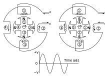
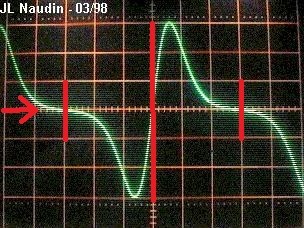
In this thread we will post information about the involved principals of electric power generators. It is very important for our research to understand how Faraday's law of induction does work practically in such a machine. It is well known that there are several different constructions, some for AC, others , like the old dynamo machines for DC output. The latter don't have much practical applications nowadays, at it is mostly easier and cheaper to rectify the AC. We will now look at the principal of a common AC generator. In the following animation you can observe how the intensity of the output current is dependent on the magnetic flux relative to the position of the output-coil. Note the phase difference between the current I and flux ɸ.
This is due to the fact, that the time rate of change Δɸ/Δt is at maximum at the moment of zero crossing of the flux, and thus the induced current is at the peak of the sine.
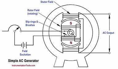
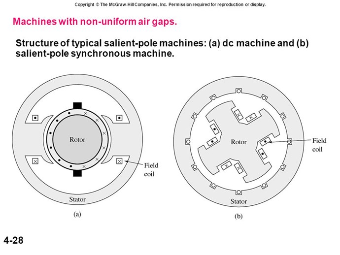
You might have noted, that in most images and animations on internet the magnets are shown static, with a coil rotating inside. This design was widely used in the dynamo machines, for DC a commutator with brushes was used in times where no semiconductor rectifiers were known. In modern versions of generators the output windings are generally on the stator, and an electromagnet powered thru brushes is rotating inside. The reason for this design is that the output power do not need to be connected by lossy brush contactors, only the relatively small amount of DC to build up the magnetic field of the rotor. Below a simplified drawing of such a generator:
It is important to note, that a generator when it is idling, without any load connected will produce virtually no resistance to the prime mover, which is spinning the shaft. The required force is limited only to overcome the friction and mechanical losses, vibration and so. Despite of this fact, the machine will output an EMF, seen as potential on the output windings.
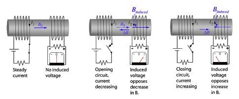
The Influence of Lenz' law:
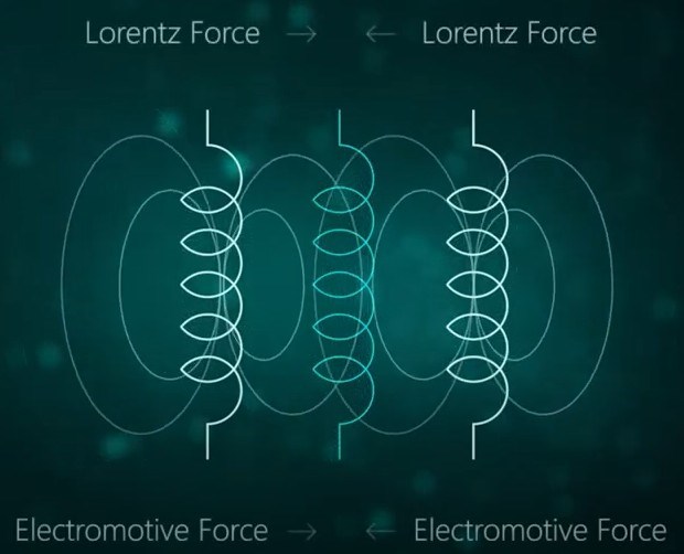
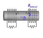
When a load is connected to the generator the following will happen: a current will flow in the output coils, and this current will produce a magnetic field in the stators ferromagnetic core. As ruled by Lenz' law, the polarity of this field will be such, that it's force opposes the movement of the rotor magnets. This happens as a symmetrical mutually opposed force-vector pair, and causes the rotor being slowed down, unless more mechanical force is applied to sustain its velocity.
And a second thing will happen: as result of the mutually opposing magnetic fields of rotor and stator, the magnetic flux density will decrease cause of the cancelling effect, and a change of impedance of the output coils will occur.
All these factors together would produce a significant drop of voltage on the output. Therefore a compensation is needed, the voltage regulator. To keep the output voltage stable, this part will respond to variations due to different load conditions with a proportional adjustment of the current, and thus the field strength of the rotor magnets.
An important detail is that the power required to setup the magnetic field of the rotor magnets is only a small fraction of the output power, and can thus easily be derived from it. Including at full load condition it is typically about 5% of the rated output power(design and parameter dependent).
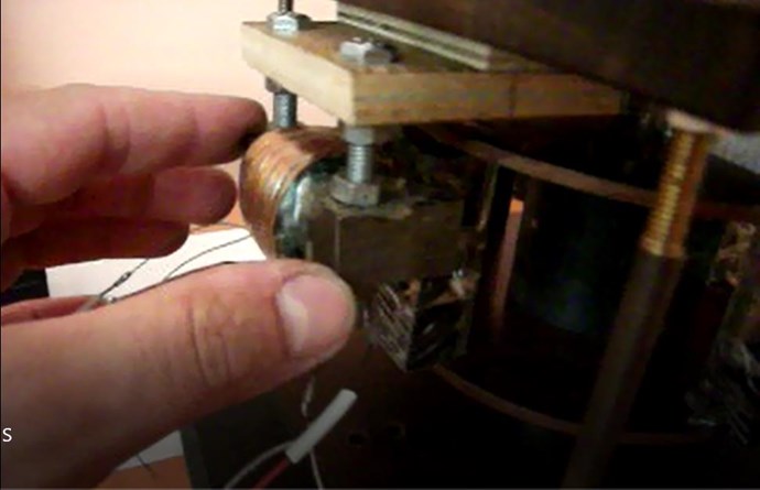
The electromagnet:
This part is generally constructed with silicone steel laminates and magnetic wire(varnished copper). There are various different designs, with two, four or more magnetic poles, depending on the RPM specifics and output frequency of the generator.
A four pole version
Eventually I did repair works on generators of a few KW rated output, and handled these rotors. In the 5 KW range this part has a weight of above 15kg I guess, it is a massive piece of metal. We know that silicone steel saturates near 2 tesla, this means if the working flux strength at full load would be around 1 Tesla, with a safety margin of 50% below saturation. This Electromagnet would have a magnetic field strength equivalent to a huge neo magnet of several kilos. The turns of the bobbin for the mentioned power range might by many hundreds, maybe approaching thousand turns, the typical applied voltage 80-100V at max. power. The current is regulated by the voltage regulator, as stated before.
The response to changing load conditions:
It is well understandable, that the electromagnet seen as an inductor, will have a considerable inductance, and thus a delayed response to any change of current flow. Anyone, who had used this kind of motor driven generators for work, will have experienced this delay as fluctuation of the output, when a significant load is connected or disconnected. If you watch this effect with attention, you will see that the voltage drops immediately, as the flux is partially cancelled by the opposing "Lenz field". But the rotation of the rotor goes down moments later, due to the inertia of the heavy and fast spinning parts of the machine. At last, the engine responds to the velocity controller, and recovers the rated angular speed(frequency). When the load is disconnected, there is virtually no overshoot in the output voltage(luckily for the connected devices). The reason is that the voltage regulator will diminish the current in the electromagnets virtually immediately, nowadays by means of fast semiconductors. In this situation the overshoot will be in frequency, until the (mechanical) speed control of the motor readjusts the RPM.
The output coils and cores:
The output coils are wound inside the stator-core, much the same as the windings as an AC induction motor. The most simple version is the single phase, with two at 180° located coil sections, which are connected in series normally. The effective area Ae of each coil matches the area of the rotors magnet pole.
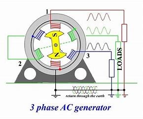
For the three phase generator there are six coils in the armature, but the same rotor with two magnetic poles(or more according the rated RPM) is spinning inside. The same as in the three phase induction motor the coils corresponding to each phase are mounted with an angle of 120° relative to the next pair. Parts of the coils are wound overlapping the next pair, in order to maintain the same Ae of the coils(not shown in the image below).
Question: Is the energy required to spin the shaft of the generator used transformed into electrical power?
Answer: No, only a small percentage needed to overcome the mechanical losses and produce the magnetic field changing in time is actually causing the electromagnetic induction.
So where do the huge amount of force (by fuels, wind, water….) going to?
Answer: It is used to fight itself in form of a symmetrically opposed force vector pair, rotor against stator , magnetic fields fighting against their counterpart, slowing down the prime mover when loaded.
Can it done in a different manner?
This is our job, I'm confident we can.
Vidura.


 And of course ... the brightness of the bulbs was higher


.jpg?width=20&crop=0,0,20,20 "fer123")


