A couple notes:
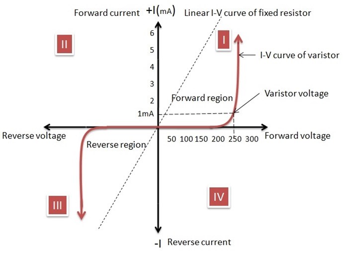
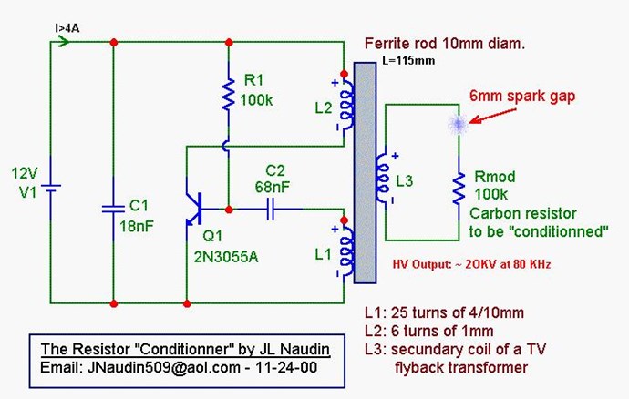
The MOV:
The MOV is used to generate a sharp spike of current and hence a sharp peak of magnetic flux. This is necessary because we're not using the transformer core in the traditional manner, which I discuss below. There are ways around that, though.
The Steering Coils:
The typical steering coil is solenoidally-wound, and thus must 'pinch' the magnetic flux in the core, thereby increasing reluctance in that path. This indirect method of increasing path reluctance requires more energy.
We are building variable-reluctance devices, so we must find the most efficient method of varying path reluctance.
Because of the solenoidally-wound steering coils, the opposite flux path typically will not get much of an assist from its steering coil, and in fact, could have its flux path through the core 'pinched' (and its reluctance increased), as well, defeating what we're trying to accomplish.
This is why my design will have spirally-wound ferrous-metal steering coils in-line with and acting as part of the magnetic circuit.
The ferrous metal of the coils have just slightly higher coercivity than the core, so when the magnetic domains in the ferrous wire are aligned by an electrical current running through the wire, the magnetic flux from the permanent magnet will follow the path of least resistance and go through the opposite flux path (especially considering that the opposite flux path will have its steering coil assisting the flux). This occurs with just enough electrical current to flip the domains in the ferrous wire, requiring on the order of millijoules. The current can be quickly pulsed to the steering coils, then shut off, and the steering coil magnetic domains will remain aligned such that they're steering the permanent magnet's flux to the desired flux path, until the steering coils are pulsed again with opposite polarity, akin to a magnetic 'switch'.
Traditional Transformers:
The way a traditional transformer works depends upon domain flipping (and thus the eddy current in the core). We don't do that. We merely pulse the magnetic flux unidirectionally, we never flip the magnetic flux vector.
Again, it's the solenoidally-wound nature of the windings. They build them that way because it's cheaper, faster and easier... not more efficient.
The primary coil of a traditional transformer has a sinusoidal current which causes spin-flipping of the valence electrons in the primary coil, which causes their magnetic field to sweep across the core, setting up a similar sinusoidal current in the core (eddy current), causing a similar spin-flipping in the valence electrons of the core material, which then cuts the secondary winding, setting up a similar sinusoidal current in the secondary winding.
This is the reason current lags voltage by 90 degrees in a transformer, and the reason secondary voltage lags primary voltage successively more as secondary load increases.
The Variable-Reluctance Transformer:
Because in our devices we're switching the flux and never reversing it in each flux path (no domain flipping), we're not going to get much 'sweep' of the valence electron's magnetic fields across a solenoidally-wound coil... we're only going to get that sweep making up the difference between the core's remnant magnetization (when the permanent magnet's flux is not traversing that flux path) and its full magnetization (when the permanent magnet's flux is traversing that flux path), not the full 'sweep' caused by a magnetic domain reversal.
The Output Coils:
The answer to this is to create toroidally-wound coils for the output coils.
To visualize this, imagine taking a winding bobbin and cutting off the flanges on each end. Then you wrap the wire through the center of the bobbin, creating a toroidal coil along the length of the bobbin. Then you place the bobbin lengthwise in the magnetic circuit. The wire would be wrapped sufficiently to fully fill the bobbin interior, and since it's ferrous wire, it'll act as its own core.
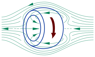
Think about how a Tokamak reactor works:

The primary winding can be anywhere on the transformer yoke.

Because a toroidal coil concentrates all its magnetic flux within its core, it doesn't appear at first glance that a changing magnetic field in the inner diameter of a toroidal coil would induce a current in the toroidal windings... except the changing magnetic field in the inner diameter of the toroidal coil has curl, thus current density is produced in the toroidal windings, in accordance with Maxwell's Fourth Equation.
All magnetic fields must have curl, and the curl of a magnetic field at any point is proportional to the current density at that point, per Stokes Theorem.
curl B = 4πJ / c Where: J = current density
An additional benefit to this is that it's somewhat akin to the opposite of a Field-Reversed Configuration magnetic confinement for fusion...
You'll note the inner magnetic field in a Field-Reversed Configuration bucks the applied field... but in our setup, we're only putting the applied field through the center of the toroid, thus it won't buck. There should be no bEMF.
As James Clerk Maxwell stated in 1861:
"Let there be a circular ring of uniform section, lapped uniformly with covered wire. It may be shown that if an electric current is passed through this wire, a magnet placed within the coil of wire will be strongly affected, but no magnetic effect will be produced on any external point."
And vice versa... the coil will be strongly affected by a changing magnetic field within the inner diameter of the toroidal coil. But a changing magnetic field outside the outer radius of the coil will have little effect.
Thus we have the most efficient means of flux-switching, and the most efficient means of converting the changing magnetic flux from the permanent magnet into electrical current.
This is the reason I've spent so much time looking for the right iron-nickel (FeNi or NiFe) wire for my design.
Additional reading material:
https://commons.vccs.edu/cgi/viewcontent.cgi?article=1084&context=exigence