Chris
posted this
14 September 2017
A repost from memory:
The Rotary Transformer uses Bucking Coils, a Concept I have been trying to introduce since at least Jul 18, 2011. This was the first video showing the concepts:
Bradley used Bucking Coils, in his RT, but now Bradley has gone quiet and is cooking Sausages on an old Oil Oven:
Brad also now rejects Faradays Electromagnetic Induction, which shows what side of the Force he is on! The Wrong Side, thus the new scopes and soldering stations he has been given. Sad, very sad.
Still History shows a different storey, and I have a full backup of it!
@ Tim You must also remember the overlap on the rotor segments to that of the brushes.This means that four rotor segments have current passing through them at once, 80% of the time. As you will see in the video's,my motor only runs at around 1200 to 1300 RPM. Dont forget that in the video of the scope trace i am using a PWM at high frequency,and also notice the half wave AC. But you will also see no switching of the rotor segments in the scope,and this is because the current flow is never broken-due to the over lap. So we have a situation were we have 2 rotor segments on,then 4, then 2 ,then 4 -and so on. This also means that your math is not a constant,and only true for 20% per revolution.
Please dont get me wrong here. What you explained is very true and correct,but there is more happening.When you get yours up and running,do a test between pulsed DC or rectified AC,and straight DC.Work out P/in for both,torque out for both,and also P/out for both. You will find that the pulsed P/in is far more efficient. In reguards to the overlap of the brushes to rotor segment's,you will find that the rotor segment aproaching the stator core,is always on-this is how they work in normal operation.So if it's always on,how dose the field around the stator core collap's?] Now like you said,the frequency of the rectified ac is very low,and it is this that makes this unit very average in performance. The frequency would need to be matched to each rotor segment,and then we would have something realy cool. But us poor men have to use what we have lol.
Anyway,i am going to dust of the old unit,and reserch it right along side you on this thread.Now i have my two channel scope,we can look at the current in,and p/out from the stator coils. This way you will be able to see exactly what is happening. As you said-this motor realy isnt good for this effect to work. But in saying that,even this motor far outperforms an off the shelf motor. Oh,and there is one other hickup we have to sort out,and that comes when you try to use two stator coil's. I havnt figured that one out yet,but i think we will have to cut the stator housing in half???.
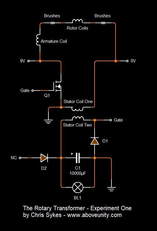
- Tinman's Rotary Transformer
You can very clearly see that Brad did not know about Bucking Coils at the date of this post: September 03, 2013
June 20, 2015 some year and a bit later, he claims he has been using them for years:
I have done this many times over the years,and yet no one wanted to really know about it,nor was much interest shown.
The L.A.G
The rotary transformer-->along with a few others.
Using the bucking coil configuration, coupled in with PM's on a stator that attract an electromagnetic field of a rotor,but appose the generated field of a generating coil,it would seem that the overall output has exceeded that of the input-->and i am pretty up to date on measuring P/in and P/out with DC system's  The latest setup seems to show a COP>+ without even having to try and measure the mechanical output to the fan. That output would be just an additive to the output. By removing the fan,the P/in go's down,and the P/out to the resistive load go's up.
But here your damed if ya do,and damed if ya dont.
So i post a video here showing what i have,and it show's a COP>+ --> then what? :
Yes-all the crap starts (as it has so many times before).
People want all the details,so as they can start there build of there own COP>+ device.
They take short cut's,and dont follow instructions,and when there device dosnt work,they call you a fake-->or the device works as stated,and now some rich prick patents the device,and were all screw'd,and im left with nothing more than i have today despite all my hard work over the years.
So rather than post all the details here MH,and have others profit from my hard work(as we seen in the case of SEC exciter being pilfered by teslatronix) How about i just post a video of the device running,and show how i am calculating my P/in and P/out-->would that be acceptable?.
From there you can pick it apart as much as you like.
Partnered Output Coils - Free Energy
Brad was keen to show off his work, the realisation came next:
So here is where im at with V3 of the rotary transformer. Adding the bucking coil setup did indeed increase the overall output of the system-both mechanical and electrical. When i say bucking coil,i mean a coil that acts as a magnet that can be switched on and off at the right time. As it is a coil that is being shorted,and thus becomes an electromagnet that pushes against the rotors collapsing field just at the right time. This field also travels around the stator core,and boost the field within the secondary(generating)coil that provides the power for the globe.
So we do have a coil that is bucking both against the rotor's field and also the field of the generating coil.
Partnered Output Coils - Free Energy
Brad worked hard, to Incorporate Bucking Coils, the Ideas and Concepts into his already existing Rotary Transformer. He succeeded, with his hard work and patience.
Chris