
Dear Friends,
I am a curious-minded hobbyist from Tokyo. I happened to find this site and conducted experiments with non-inductive coils based on the instructions provided here. They produced some positive results that I think are worth sharing with you.
I have found the Aboveunity site a few year ago. I have been studying Electromagnetism and Electric and Electronic Circuits ever since and finally enabled myself to build this machine, and conducted related experiments. Unfortunately, though I have found myself having some issue which prevents me from further experiments. I have but to give up everything including my machine , measurement tools and etc for that reason. So, I have decided to do things that I could do to support your activities. Besides this report, I have some theoretical ideas that I am planning to up-load in the future post.
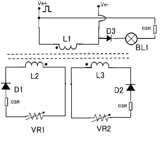
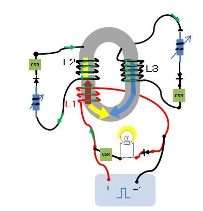
1. Circuit schematic and its graphical explanation
The schematic I used is almost identical to the one introduced in the builder's guide.
2. Settings and Specifications
CORE: AMC320, 4 blocks (CSR doubled with cores paired in parallel)
COPPER WIRE DIAMETER: 1.2 mm
INPUT COIL: Length 7 mm, 44 turns
OUTPUT COIL: Length 24 mm, 175 turns × 2
INPUT FREQUENCY: 33 kHz
DUTY: 25%
3. Results of the First Experiment
(1) The effect was verified:
When both VR1 and VR2 were set to zero resistance, sawtooth waveforms were observed, and the Lenz’s variant effect was verified.(the COP was below 1.0)
Results: I/P: 19 mA × 10 V; O/P: 17.5 mA × 8 V + back EMF.
The other coil’s O/P is negligible
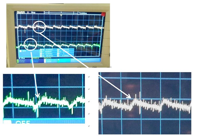
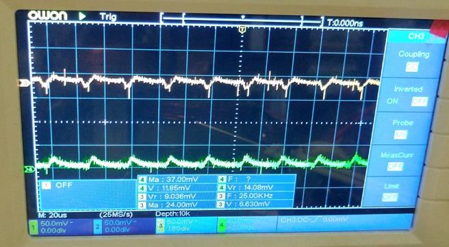
(2) A gain above unity is achieved with the resistances of VR1 and VR2 each set to 1 kΩ. The waveforms were distorted simultaneously.
Frequency: 33KHz Duty: 20%
Result: I/P: 25 mA × 12 V; O/P: 20 mA × 9 V + 14 mA × 5 V + 4.6 mA × 12 V (back EMF). COP is slightly above unity.
(3) Some funny results
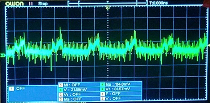
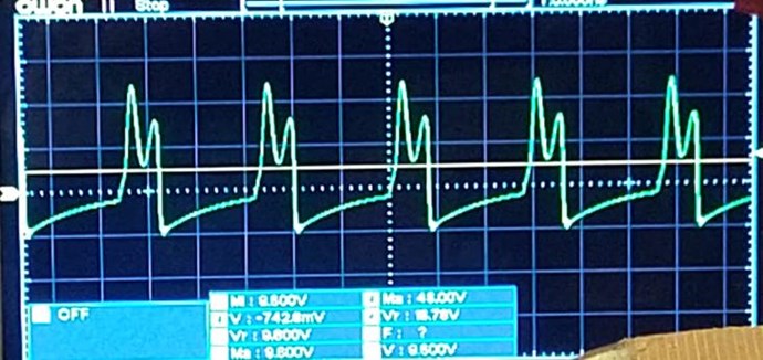
In the first place, I started this experiment with a single pair of AMC320 cores. The results were actually better with a single CSR and more turns in the O/P coils than with a double pair and fewer turns. I am not very confident in this setup because of the strange waveform of the O/P voltage, as shown in the photo below. The problem disappeared after I fixed the self-made signal generator. However, I decided to retain this result as one piece of evidence because the combination of the O/P current and VR1 resistance approximately follows Ohm's law, supporting the otherwise controversial measurement of the current value. My idea is that as far as COP is below 2.0, O/P should follow ordinarily Ohm’s law.
CORE: AMC320, single pair
WIRE DIAMETER: 1.0 mm
INPUT COIL: length 20 mm, 90 turns
OUTPUT COIL: length 50 mm, 350 turns × 2
I/P FREQUENCY: 17.7 kHz, DUTY: 25%Result
With VR1 830_Ohm and VR2 zero, COP is around 1.7 .
Result: I/P: 21 mA × 9.8 V; O/P: 20 mA × 16.7 V + back EMF
The other coil's O/P is negligible.
Strange double bumps of O/P voltage were caused by settings of my DIY signal-generator module with a variable resistance to control I/P voltage.
a) A photp below is I/P current, strange double bumps can be seen which is fixed later:
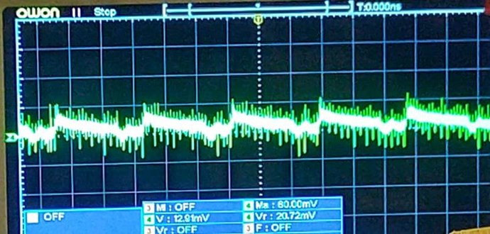
b) Wave shape of O/P current for the above I/P:
c) Wave shapes of voltages :
MY MACHINE:
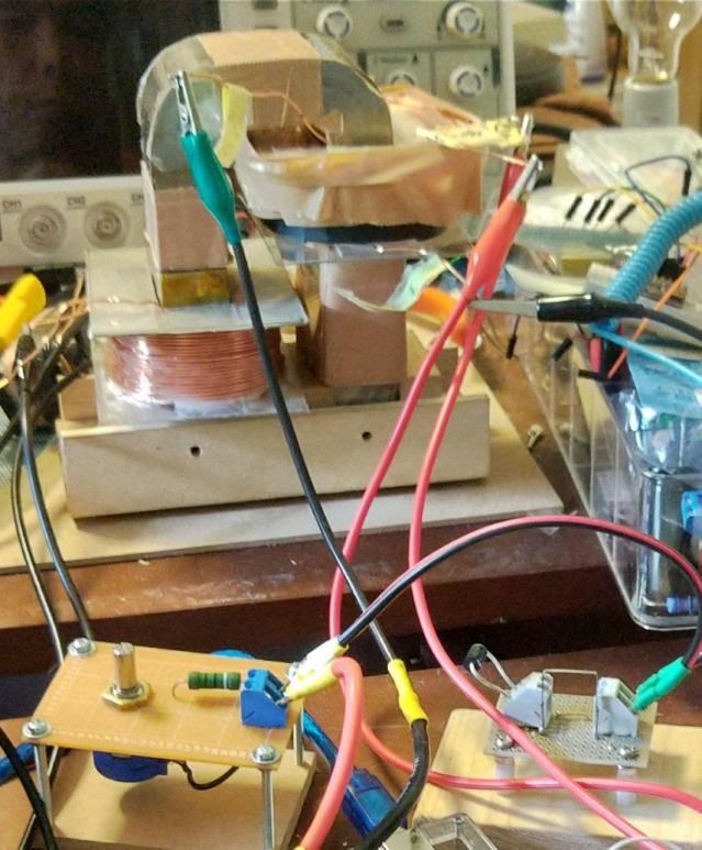
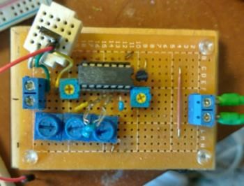
Self made PWM module(IC:TC74HC14AP )