Transformers: how do they work?

  • Topic Is Sticky
  • 942 Views
  • Last Post 22 August 2021
Vidura posted this 18 August 2021

Hello friends, this thread is intended to bring some clarity about the principals involved in the operation of different types of transformers. In first place I want to encourage all of you to think critically about some things widely accepted as theory, which has been told us by textbook physics so many times, that including most of trained engineers repeat them like parrots.

Let’s start with some very basic things, which I would like to show you in the following experiment:

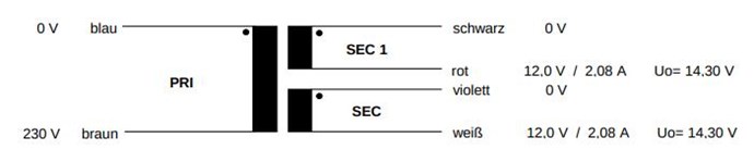
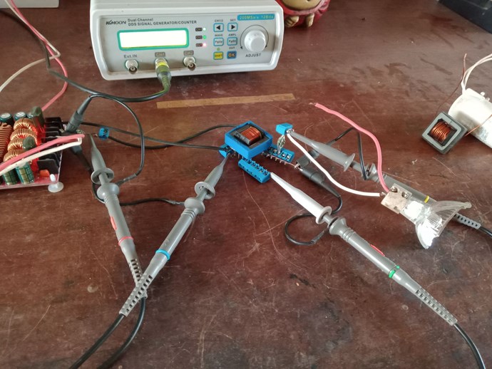
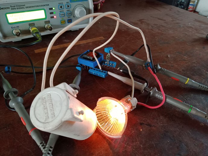
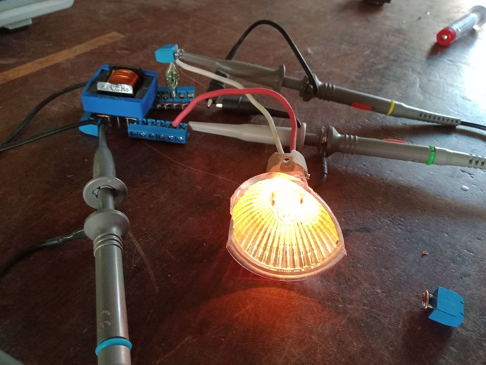
The setup is very simple, a small ferrite transformer with one primary and one secondary winding. The ratio is a slight step-up of 1:1.2(not critical). An audio amplifier is used to produce the input for the primary winding. The scope is connected as follows: Ch1(blue) primary voltage, Ch2(green) secondary voltage, Ch3(red) primary current, Ch4(yellow) secondary current.

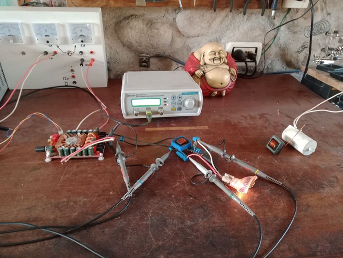
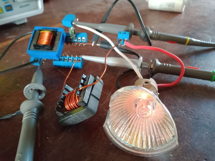
Here some images of the setup:

The transformer is observed in four different load conditions.

  • No load, secondary open circuit.
  • Inductive load, simulated with an additional inductor in series with a halogen lightbulb.
  • Capacitive load, simulated with an AC capacitor in series with the lightbulb.
  • Resistive load, the lightbulb only.

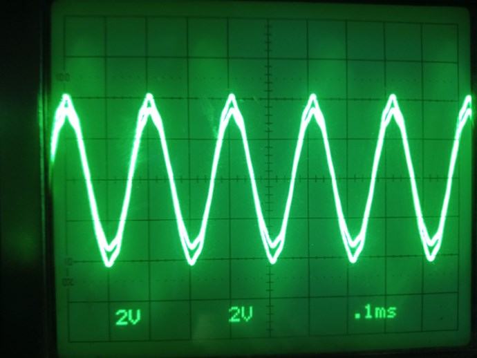
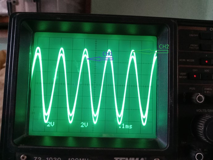
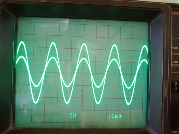
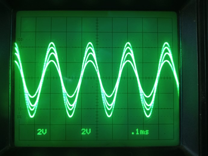
Let’s look at the scope shots in the first load condition:

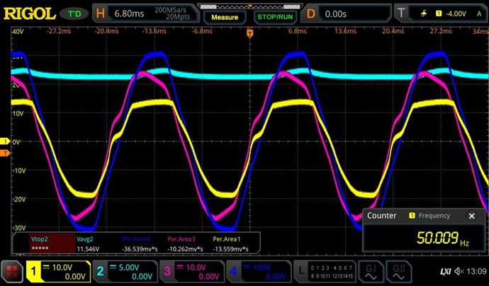
Unloaded, secondary open circuit.

We can see that the primary and the secondary voltage are in phase, and also a small distortion is perfectly transmitted, the input current is reactive, close to 90° as expected from theory.

Now let’s see the following load condition:

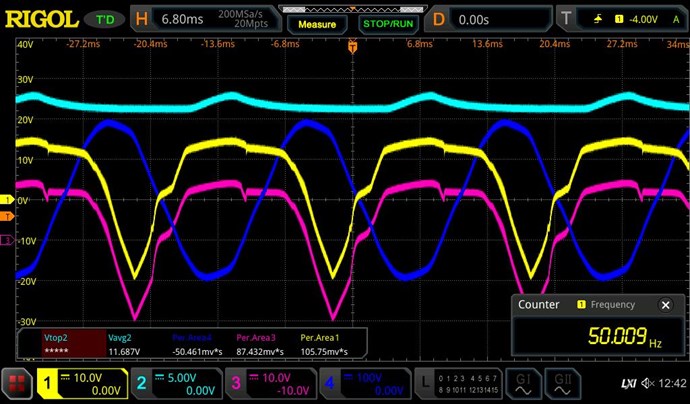
An additional inductor is connected in series with the light bulb.

As the output becomes predominately reactive, only a faint growing is visible.

The scope traces:

Primary and secondary voltage, perfectly in phase.

The secondary current is lagging behind the voltage, as expected for an inductive load.

The primary current phase is also shifted to the lagging side.

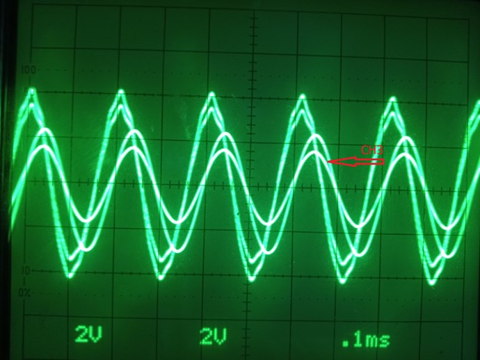
Now let’s see what happens when we connect a capacitive load, we can simulate this by connecting an AC capacitor in series with the load:

Again, the voltage of primary and secondary are perfectly in phase.

The secondary current is leading the voltage.

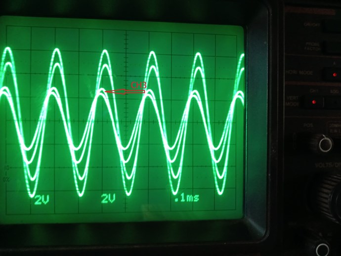
Also, the primary current is shifted to the leading side.

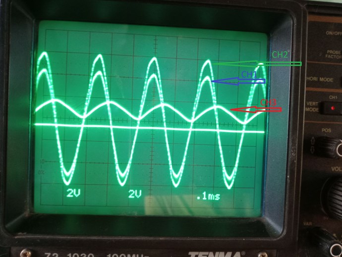
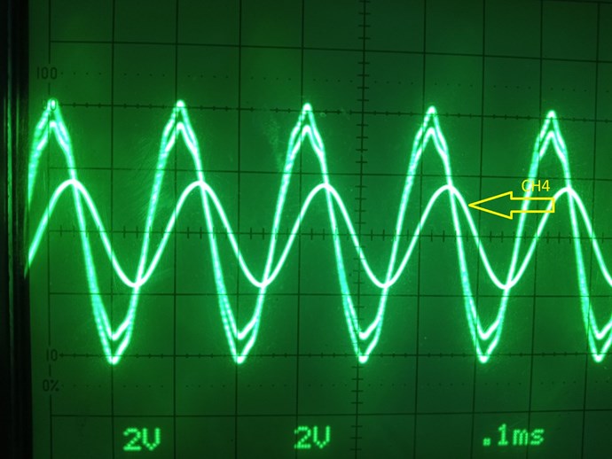
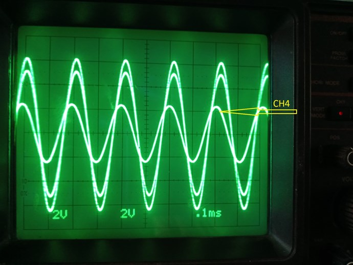
Now finally we will look at the traces with a resistive load connected:

Secondary voltage and current:

Primary voltage and current:

We can see a slight lagging of current; this depends on the amount of power extracted on the secondary side.

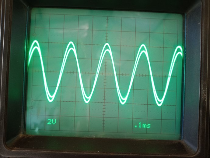
Finally all four traces superimposed, again we can see the voltages of primary and secondary exactly in phase:

If we think about these results, we can make some conclusions for the instance. We see clearly that in all four load conditions the voltage on primary and secondary of the transformer are in phase.

But how is this possible, can anyone explain by using Faraday’s law of induction, how the voltage in the secondary winding is induced exactly in phase, while the currents are shifted to the leading or lagging side in different degrees?

 And although with a predominately resistive load we have no change of current-magnetic flux at the moment of maximum voltage.

We can observe that the phase shifting on the secondary depends only on the reactance of the load (inductive or capacitive), and that this phase shifting is also reflected to the primary side.

So , if it is not the change in current which induces the EMF in the secondary, what is it then?

To be continued...

Vidura

Attached Files

Order By: Standard | Newest | Votes
Chris posted this 22 August 2021

Hey Baerndorfer,

Scope Traces on the first Scope Shot, I believe according to the Right Hand Grip Rule, you may have one or more Probes on backwards, if one trace is measuring Secondary Voltage, then it should be inverted to the Primary Current, technically.

In Phase and with the same polarity is not what Lenz's Law gives us. So we must observe this cavaet. I am being picky, yes I know, but the advanteges we have gained over the other forums were done very easily by observing some very simple phenomena, with Scientific Eyes and interpreting the results with fresh and maticulous eyes.

You always do excellent work My Friend, Thank You for Sharing! Your observations are first class!

Really, the workings of a Transformer should be 100% known already.

Best Wishes,

   Chris

  • Liked by
  • baerndorfer
baerndorfer posted this 22 August 2021

because this is about transformers i like to show you some findings...

for this test i ordered some of these transformers (toroid core):http://www.sedlbauer.de/media/ringkerntrafo_datenblatt_826020.pdf

826020

to do a test under load i rectified the AC to DC and connect a 12V battery (90Ah) for charging on SEC1. 

this is what i see on my scope..

CH1 (yellow): Secondary Coil SEC1 -> charging battery
CH2 (cyan): Battery Voltage
CH3 (pink): Secondary Coil SEC -> open circuit
CH4 (blue): Primary Coil

then i rewind the secondarys from transformer to meet POC-style.

this is what it looks like on scope..

you will notice a phase shift between primary and secondary
and what is even more interesting...
the cycle area on the poc coils shows whats happening on the magnetic side of the story...

regards!


  • Liked by
  • Chris
  • strape
Chris posted this 20 August 2021

My Friends,

It is very easily proveable that the Change in Magnetic Field, creates a Voltage, then as the Voltage is created, Current can flow.


We can not say, because we do not see a phase angle, that Faradays Law does not hold, we can not say this!

An investigation into Phase Ahgle is whats needed, to see why Phase Angle is lost, and as I pointed out, Inductance and Impedance changes with Load, the Load on the Machine will change your Phase Angle.

It is true: EMF = -N dΦ / dt or: EMF = -N dB / dt, and it is also true to state: EMF = -N dI / dt

Faradays Law holds and todays technology depends on this very simple set of equations and laws.

Faradays Law is incomplete, it can be extended to into Asymmetrical Machines, but the basic Law still holds and is in no way deminished at all. This Law can occur more than once in a single Machine, I have shown this here: @30 : 14


My Friends, Experiment is the path forward, but we must interpret the results for whats really infront of us.

Best Wishes,

   Chris

  • Liked by
  • strape
  • raivope
baerndorfer posted this 20 August 2021

hmmm...
because we are dealing with electrons the magnetic and electrical impulse comes from the same source (Don Smith)

electron spin clockwise ==> magnetic impulse
electron spin counter-clockwise ==> electrical impulse

so anytime when we disturb an electron by pushing it forward, it gives off magnetic impulse. when it pops back to where it came from, it gives off an electrical impulse.

in a transformer the electrons which are energizing the primary coil are NOT the same electrons, which happen on the secondary side. the one from secondary are driven by a potential difference which comes from the coil. the secondary coil itself got its power (potential) from the magnetic flux lines which run through the coil and this is what we can measure as voltage.

regards!

Chris posted this 19 August 2021

Hello friends, there might be some confusion, I think it was my fault to take voltage as EMF and vice versa. I am sorry for that, and have corrected the corresponding parts in the post. So, let’s clarify: Voltage is a potential difference between a potential-reference and any test point measured in volts. In contrast the EMF (electromotive force) is an external force exerting on the charge carriers, also measured in volts. Thus, the EMF is the force that makes current flowing. In this context Faradays law: EMF = (-) d/ᶲ d/t means that the change of flux is exerting a force on the charge carriers, which is giving rise to a current flow. Having clarified this, we are still confronted with a lack of explanation, how the voltage is induced in the transformer, and why it is always in phase between primary and secondary, regardless of the phasing of the currents.

PD, I did the experiments also with silicone steel core at 50Hz, with the same result, but as it is a pain sticky task to work on low frequencies with the CRT scope, i took the ferrite version for posting.

And I want to remark again that i kept the core far from saturation value, you can observe that well in the clean sinewave shape of the current traces.

Regards Vidura


Hey Vidura,

Sorry My Friend, I do not agree with you in this post.

Electromotive Force ( E.M.F ) is measured in Units of Volts, its the measure of the same thing.

Faradays Law holds, the Change in B, the Magnetic Flux Density, induces an E.M.F, measured in units of Volts. There can be a small propagation delay, due to Core, and other factors, but the Input Current I, is the Magnetising Force, which creates the Magnetic Field B. As B increases, then I must have increased to cause this change. When B on the Primary Increases, the Secondary Voltage is Produced as a factor of the turns N. Opposite in Sine due to the Lenz's Law Negative Sign.

This is where Power Factor comes in, or we would not need Power Factor, to correct for Phase.

This video shows a little bit of the experiment:


I will setup an experiment and show it if necessary?

Sorry My Friend, I think more work is needed here to clarify this confusion.

Best Wishes,

   Chris

Vidura posted this 19 August 2021

Hello friends, there might be some confusion, I think it was my fault to take voltage as EMF and vice versa. I am sorry for that, and have corrected the corresponding parts in the post. So, let’s clarify: Voltage is a potential difference between a potential-reference and any test point measured in volts. In contrast the EMF (electromotive force) is an external force exerting on the charge carriers, also measured in volts. Thus, the EMF is the force that makes current flowing. In this context Faradays law: EMF = (-) d/ᶲ d/t means that the change of flux is exerting a force on the charge carriers, which is giving rise to a current flow. Having clarified this, we are still confronted with a lack of explanation, how the voltage is induced in the transformer, and why it is always in phase between primary and secondary, regardless of the phasing of the currents.

PD, I did the experiments also with silicone steel core at 50Hz, with the same result, but as it is a pain sticky task to work on low frequencies with the CRT scope, i took the ferrite version for posting.

And I want to remark again that i kept the core far from saturation value, you can observe that well in the clean sinewave shape of the current traces.

Regards Vidura

  • Liked by
  • Chris
  • YoElMiCrO
Chris posted this 19 August 2021

My Friends,

I want to clarity, when I said:

Phase depends on Load, and close to or at Saturation, V and I Phase changes. Your experiments, most, you were in Saturation, seen by the sharp peaks on the sine wave. Thats why you saw very little to no Phase Angle.


The Coils Inductance changes, as the Load is Increased or Decreased, that's why the Phase Angle changes, its not directly the Load that does this, its the Transformer Coils that do this, but the Load Changes the Coils Inductance, remember the definition of Inductance is the ability for a Coil to Carry a Current.

At Saturation, there is no more Inductance, Inductance is Lost, the Coils become just a Resistor, Impedance becomes the DC Resistance, and the Coils can very easily Burn Out:

What was many Ohms of Resistance, Impedance Z, now becomes DC Resistance R, which is always many times lower than the Impedance.

I think a Transformer Study, comparing E I Silicon Steel Core, as a comparison, would be of great benefit here!

Best Wishes,

   Chris

  • Liked by
  • Vidura
  • strape
Chris posted this 19 August 2021

Hey Raivo and Atti,

Good to have you back with Us!

You are right, Experiment is the path forward, then we can better simulate the Machines we build!

It seems to me, thinking in an Asymmetrical manner, is on the difficult side for many! Because of this, we have missed many effects in Science! Symmetry, For every Action there is an equal and opposite Reaction, is easy for most and Science has focused exquisitely on this for a very long time!

The truth is, there is often: For every Action there is an equal and opposite Reaction, and for every Reaction there is an Equal and opposite Counter-Reaction.

This gives us Asymmetry and completes Science, this is the Unified theory if one applies this to all of Science to see where it holds and does not hold. I believe this is effective on Inverse Square Law principles, but may not work on some othere.

Best Wishes,

   Chris

  • Liked by
  • Vidura
Chris posted this 19 August 2021

Hey Chris, it is not easy to see the subtle differences, I would like to remark that I do not state that current- flux is not involved in the appearance of the EMF, but I stated that Faraday's Law is not sufficient for the explanation of the observed scope traces, there is something different responsible for the appearance of the secondary voltage. Regarding the saturation, in the shown experience the core was far from saturated, around 50% . As you have now a four channel scope, you can check this easily yourself. I am confident that it will be of great benefit to do further investigation on this, only if we go ahead open-minded we will be able to gain mor complete understanding. Regards Vidura.


Ah, yes I see what you mean now. Thank You for clarifying!

Floyd Sweet wrote:

Electromagnetic induction with no measurable magnetic field is not new. It is well known that in the space surrounding a properly wound toroidal coil there is no magnetic field. This is due to the superposition of the fields. However, when alternating current is surging through a transformer an electric field surrounds it.


And Sir Richard Feynman said:


So yes, I and B if they change, we get an Electric Field.

Best Wishes,

   Chris

  • Liked by
  • Vidura
  • strape
Atti posted this 19 August 2021

Hi.

We can observe that the phase shifting on the secondary depends only on the reactance of the load (inductive or capacitive), and that this phase shifting is also reflected to the primary side.


Because the Change in Current is equivilent to the Change in Magnetic Field, we can write: EMF = -N di/dt


I’m glad he’s preoccupied with these issues. Very good experiment!

Reflection on the primary page is, in my opinion, the key to moving forward. (after all, if I understand correctly, Chris also tells us this, the point would be)

If energy gets to the primary side (from somewhere) then the ideal state can be realized. Either the energy absorbed is reduced or full self-sufficiency can be achieved.
Think of the connection between the POC coils. Think of Chris's state of magnetic resonance.
What I am showing now is not the ideal state.
This is just a demonstration.

I would demonstrate the magnetic resonance with the current of the capacitor. (infertile state, but only in half a wave. see oscilloscope figure. this change in secondary current causes an increase or decrease in energy in the primary. But its voltage is definitely displayed. Visible at 5:15.
I've shown something similar before.)
In ideal condition
(difficult to set with many parameters)
resonance occurs. In my experience so far, it is realized when the coupling of the transformer is loose. An example of the strength of the video at the end (6:05) is the current recharge. It shows well what happens if the coupling is tight or the coupling is loose.

This resonance is due to the presence of the two magnetic fields.

Atti.


Vidura posted this 19 August 2021

Hey Chris, it is not easy to see the subtle differences, I would like to remark that I do not state that current- flux is not involved in the appearance of the EMF, but I stated that Faraday's Law is not sufficient for the explanation of the observed scope traces, there is something different responsible for the appearance of the secondary voltage. Regarding the saturation, in the shown experience the core was far from saturated, around 50% . As you have now a four channel scope, you can check this easily yourself. I am confident that it will be of great benefit to do further investigation on this, only if we go ahead open-minded we will be able to gain mor complete understanding. Regards Vidura.

raivope posted this 19 August 2021

Hi All!

Great to have this site back!

Some time ago I was busy writing a simulator in Java to emulate magnetics, because current "free" simulators cannot simulate well multicoil or 3PH transformers. At least I can already simulate LC, but multicoil environment with different flux coupling is still behind the mountains... crazy task.

Still - the best "free" simulator there is - is SiMetrix.

What I learned during writing a simulator is that we can make a model to have a superposition (sum of all) charge movement (moment).

Imagine there is a big heavy wheel - you need volts to push it, where wheel movement is a current. Of course - when there is low coupling between the coils then there are different flux paths - meaning there are multiple wheels that generate flux.
So - assume also that magnetic field does not exist (it is just a force) - there exists only one thing and it is a (virtual)rotation of charges. So - the same is a magnet - having virtual rotation of charges. Because movement of charge creates the magnetic field. Or electron moment creates the field. Free magnetic dipoles in ferromagnetics then they become aligned they add to the common charge moment creating (amplifying) the field. But first we have to use force (BEMF) to push dipoles to the position. It is exactly the same that when we need to use force to rotate the spinning wheel. So - now we have a model for force, voltage and a current and all is in superposition of the single moment of moving charges.

Having a mechanical analogue of explanation we are now back in a box (mathematically too) - or a closed system where what we invest we get back and nothing is free because we cannot break the model. Any way you try to push the wheel you have always a background-reference moment system where you cannot have gains. Trying to trick it by pulsing, different voltages, angles, should result the same zero game.

If you have a POC and you take a proper Simulator - pulse the Input Coil, conduct the POC1, POC2 to simulate the opening the diodes - can you prove that the POC2 will assist the input? If it has been easy to explain it in words, then there is also a way to simulate it in the mathematically-organised environment where you take into account all the factors. What would be the outcome?

I am quite sure there is nothing there.

Before you get too much depressed, I still can see the tunnel in the end of light!

The thing is what the simulators do not take into account are:
- the light-speed (wave-resonance), phase change during wave resonance.
- bucking effect (wave reflection, E/M + E/M = 2*E + 0*M, i.e. charge creation)
- bucking effect - when fields cancel (something else may enter the system from the environment during the zero field) - similar to the thing what Bearden talks about when all the flux is inside the Crystalline Core, environment takes over.
- cold electricity / negative resistance phenomenon taking place because of coil reaction to each other in a nanoseconds' scale - interacting with or gaining electrons/positrons/ions from environment
- or Ferromagnetism actually IS the open nonlinear system where our mathematical model should be extended (to become assymmetric)

I guess - those are the factors that create something (from nothing).

Best,

Raivo


Chris posted this 19 August 2021

Hi Vidura,

When you state:

Yes of course current is involved in the principles of the transformers, what I wanted to point out is that the voltage of the secondary is not related to the d/I d/t rate as clearly can be observed in the experiments. 


I would like to point out, di/dt is the Rate at which Current Changes, this is the Transformer Magnetising Current, which is directly responsible for the BH Curve.

Phase depends on Load, and close to or at Saturation, V and I Phase changes. Your experiments, most, you were in Saturation, seen by the sharp peaks on the sine wave. Thats why you saw very little to no Phase Angle.

I show this, Input Current Creates Output Voltage here: @26 : 07


I have to say, as it stands, I do not agree with your statement.

Perhaps I missunderstood your reply?

Best wishes,

   Chris

Vidura posted this 19 August 2021

@melendor Yes of course current is involved in the principles of the transformers, what I wanted to point out is that the voltage of the secondary is not related to the d/I d/t rate as clearly can be observed in the experiments. As ferrite is a magnetic fast material, we can assume that the magnetic flux is virtually in phase with the current, and therefore applying Faraday's Law is not consistent to explain the appearance of the voltage traces we got. It is related to the voltage applied to the primary and the Np/Ns relationship, and always in phase with the former. DC pulsed transformers are more complex, many different topologies with different operating principles exists. I will show an equivalent example later . Regarding the phases of the currents, it is just the way you hook the probes, basically it is the opposite polarity (magnetically), but for illustration purposes of the timing I preferred to show the traces of the same polarity. Regards, and thanks for your interest.

Chris posted this 18 August 2021

It may be wrong....but this is what I have observed from my experiments and this is what I have heard that Chris has said in some of his video. Current I induces EMF.

Hey Melendor the wizard,

If I may, you are right in what you say, but a small adjustment needs to be added.

It is the Change in Chrrent that Induces an EMF. Mathematically, this is di/dt

Because the Change in Current is equivilent to the Change in Magnetic Field, we can write: EMF = -N di/dt


What I DO NOT understand , is why is the Current in phase ??? 
Once you load the Secondary , you must have a 180 out of phase between I primary and I secondary.
Lenz Law.

The secondary opposes the change in magnetic field that original created it.


You are right, and this part is somewhat confusing. Keep what you have, "180 out of phase between I primary and I secondary", this is the case, but extend this a little, add another Coil, and make sure the Secondary Coil is the Tertiary Coils Source.

So the process would be:

At Time t = 0: we have no Conduction in all Coils in our machines. No Current Flows.

At Time t = 1: we have Input Coil Conduct with the Switch On of the Mosfet, Current Starts to Flow.

At Time t = 2: we have Electromagnetic Induction between your Input Coil and POCOne , POCOne Conducts when the Diode Voltage is at threshold Voltage, normally 0.5 to 0.7 Volts.

At Time t = 3: we have Current Flow in POCOne, this Current starts to Change in Time also, Electromagnetic Induction occurs between POCOne and POCTwo.

At Time t = 4: we have POCOne's Current induce sufficient Voltage in POCTwo and then at 0.5 to 0.7 Volts, POCTwo then Conducts.

Here you can see, we have a Delay in Conduction, the Coils are delayed in Time T, and as a result, they Slap Together, which is Electromagnetic Induction in your Machine for a Second Time!


EDIT: All we have done, is extend Electromagnetic Induction, Induction is typically 180 Degrees, do this again and we get another 180, so 180 + 180 = 360, so your Tertiary Coil Assists your Input Coil. Very simple once one puts the pieces together.

Great post, nice to see!

Best Wishes,

   Chris

Melendor posted this 18 August 2021

Hello Vidura.
Thank you very much for the post and for your work.

I really think that the Current in the primary induces an EMF ( voltage) in the secondary.

I have done the experiment with an Isolation trafo 1:1 ratio and a 20mA signal generator
The voltage on the secondary was 20 v.
When i used the DC mosfet switch and pushed 0.5 A in the primary...the voltage on the secondary was 200 V .
More current in the primary..more EMF on the secondary.

It may be wrong....but this is what I have observed from my experiments and this is what I have heard that Chris has said in some of his video. Current I induces EMF.

Vp and Vs are in phase because the winding direction is the same CW-CW and you are probing both coils at the beginning of the winding ( I think )

What I DO NOT understand , is why is the Current in phase ??? 
Once you load the Secondary , you must have a 180 out of phase between I primary and I secondary.
Lenz Law.

The secondary opposes the change in magnetic field that original created it.

Thank you again for the post.
We need more post like this,where we can interact and observe together.

Stay safe.
*Melendor the wizard


We're Light Years Ahead!
Members Online:

No one online at the moment


What is a Scalar:

In physics, scalars are physical quantities that are unaffected by changes to a vector space basis. Scalars are often accompanied by units of measurement, as in "10 cm". Examples of scalar quantities are mass, distance, charge, volume, time, speed, and the magnitude of physical vectors in general.

You need to forget the Non-Sense that some spout with out knowing the actual Definition of the word Scalar! Some people talk absolute Bull Sh*t!

The pressure P in the formula P = pgh, pgh is a scalar that tells you the amount of this squashing force per unit area in a fluid.

A Scalar, having both direction and magnitude, can be anything! The Magnetic Field, a Charge moving, yet some Numb Nuts think it means Magic Science!

Message from God:

Hello my children. This is Yahweh, the one true Lord. You have found creation's secret. Now share it peacefully with the world.

Ref: Message from God written inside the Human Genome

God be in my head, and in my thinking.

God be in my eyes, and in my looking.

God be in my mouth, and in my speaking.

Oh, God be in my heart, and in my understanding.

Your Support:

More than anything else, your contributions to this forum are most important! We are trying to actively get all visitors involved, but we do only have a few main contributors, which are very much appreciated! If you would like to see more pages with more detailed experiments and answers, perhaps a contribution of another type maybe possible:

PayPal De-Platformed me!

They REFUSE to tell me why!

We now use Wise!

Donate
Use E-Mail: Chris at aboveunity.com

The content I am sharing is not only unique, but is changing the world as we know it! Please Support Us!

Thank You So Much!

Weeks High Earners:
The great Nikola Tesla:

Ere many generations pass, our machinery will be driven by a power obtainable at any point of the universe. This idea is not novel. Men have been led to it long ago by instinct or reason. It has been expressed in many ways, and in many places, in the history of old and new. We find it in the delightful myth of Antheus, who drives power from the earth; we find it among the subtle speculations of one of your splendid mathematicians, and in many hints and statements of thinkers of the present time. Throughout space there is energy. Is this energy static or kinetic? If static, our hopes are in vain; if kinetic - and this we know it is for certain - then it is a mere question of time when men will succeed in attaching their machinery to the very wheelwork of nature.

Experiments With Alternate Currents Of High Potential And High Frequency (February 1892).

Close