Utilizing a Single Shot Sinusoidal Pulse

  • Topic Is Sticky
  • 784 Views
  • Last Post 23 January 2023
Chris posted this 08 January 2023

My Friends,

The Input Coil on Free Energy Machines is a very critical Factor! One must think about the Actions and Reactions of this Input Coil with great Intent! A Short DC Pulse is sufficient in many situations, but can we do better, can we give better precision, better success, better control of this very important Excitation to your Partnered Output Coils?


Why?

In Faradays Law of Electromagnetic Induction, we have a Δt Variable, which is the Time Rate of Change, we also have a ΔB which is the Rate of Change of the Magnetic Field over this period of Time ( t ). The symbol Δ ( Delta ) typically means "Change". The Rate at which a Variable Changes.

Faradays Law of Electromagnetic Induction, in the Equation Form, is a Derivative. This means we need to observe the Rise over Run:


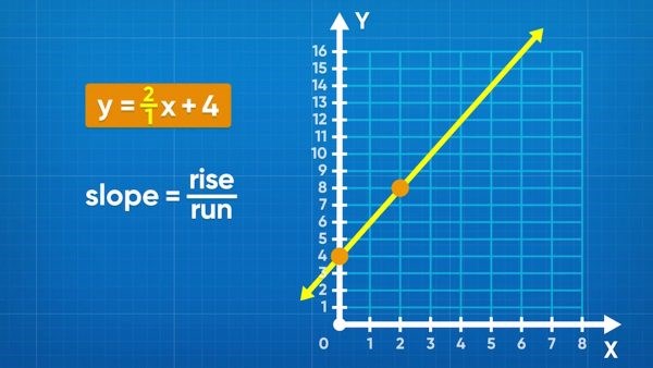
This means, the steeper the Slope we are dealing with, the faster the Magnetic Fields Change.


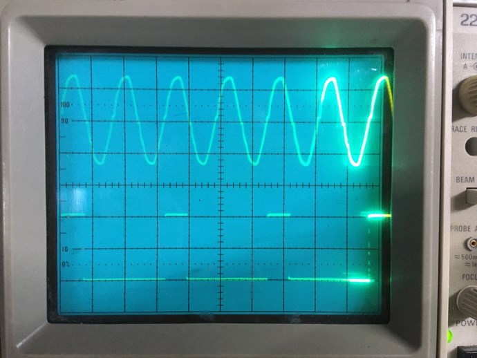
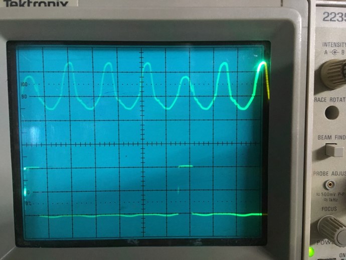
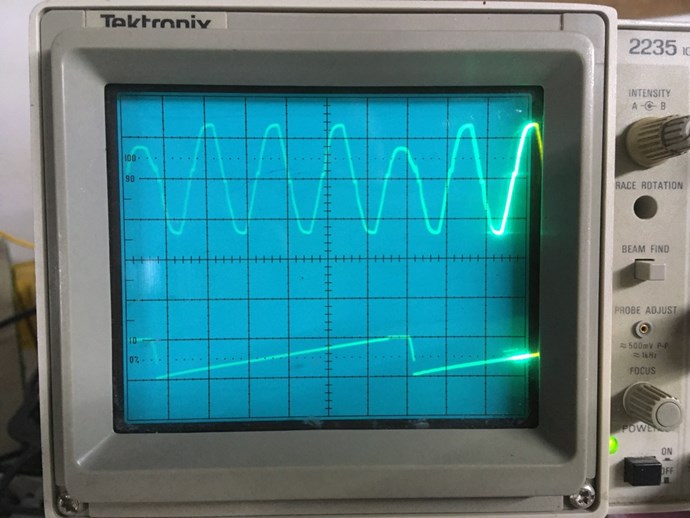
A DC Pulse applies a Voltage of X to the Input Coil, and the Coils Inductance allows a Current to Build exponentially:


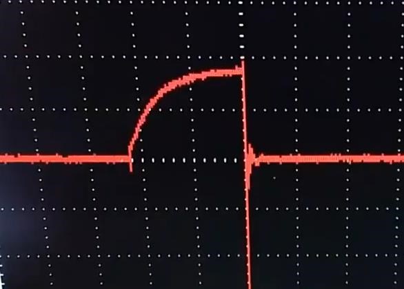
This, the above Scope Shot, is the Current ( I ) Changing in Time, so this is a ΔI / Δt, that you see, but we know that Current ( I ) is analogous to the Magnetic Field ( B ) so we can say this is the same as the Magnetic Field ( B ) Changing in Time ΔB / Δt. The X Axis ( Left to Right ) is Time and the Y Axis ( Vertical, up and down ) is Measured Potential.

As I have shown in my video:


This Change in Current ( I ) over Time, or the ΔI / Δt on your Input Coil "Generates" a Voltage ( V ) on your Output Coil!

So, in a DC Pulsed Circuit, on the Input, we are somewhat limited to the Input Coils Inductance, and the Voltage applied across the Input Coil at TOn of the Mosfet. 


Can we do better than a DC Pulse?

Yes, but this is experimental at the moment.

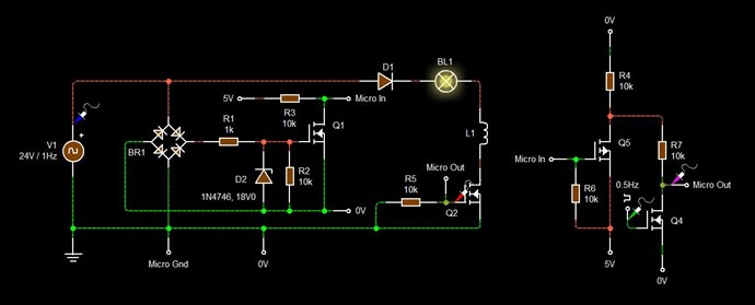
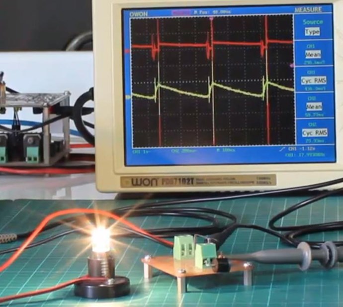
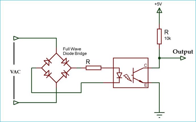
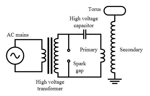
We need to detect the Zero Crossing of any given Sine Wave that we wish to Input! The best Circuit I have found for this is this Circuit:


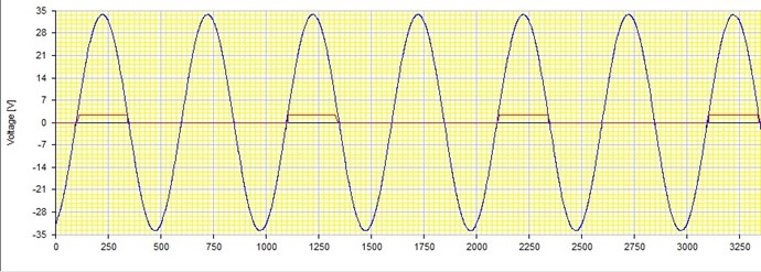
The Output will be the Wave in Red:


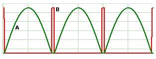
From here, you could use a Micro Controller to Count the Pulses, and trigger a Mosfet, Triac or whatever, every second pulse or whatever, for the duration of only one pulse, or something similar.

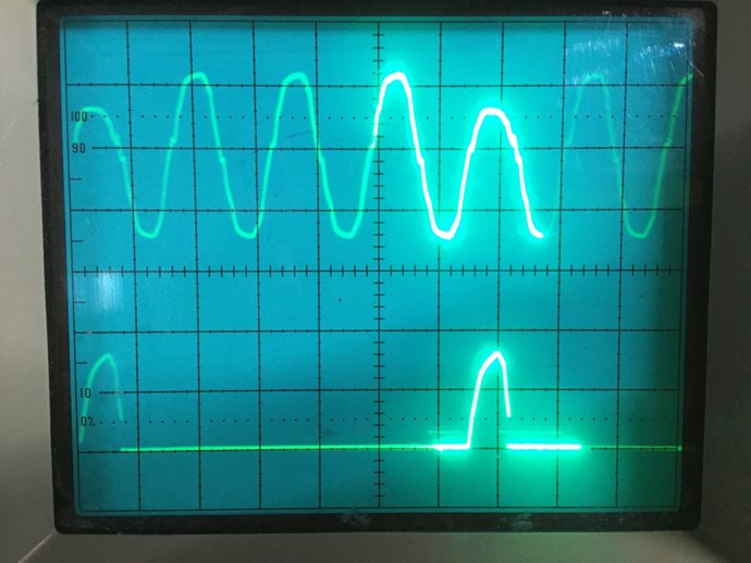
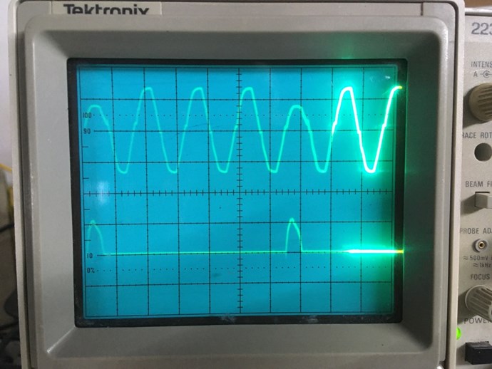
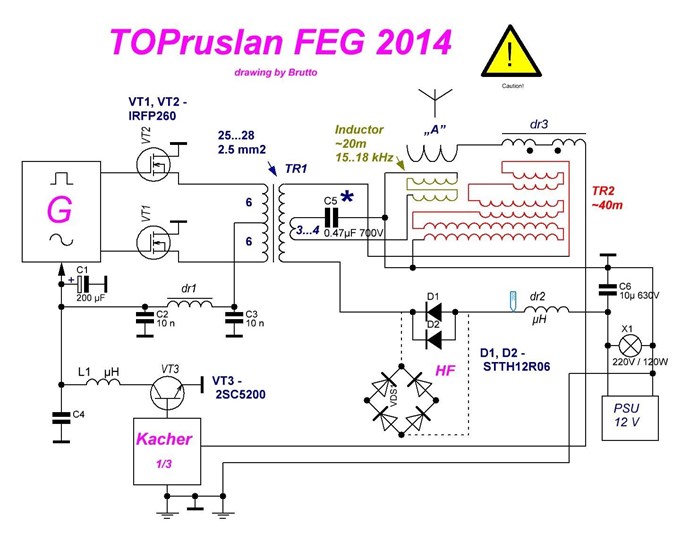
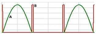
In many of My Videos you have seen me use an Audio Amp on the Input, sending a Sine Wave into the machine, well, this gives us a way to send a single shot, half AC Wave, to the Input Coil, and its adjustable in Frequency. So your Input Coil would see ( In Green ):


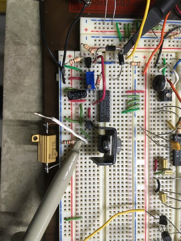
I think its important to remind everyone about Floyd Sweets first Successes, the initial, or first Space Quanta Modulator, used Diodes on the Input Stage:

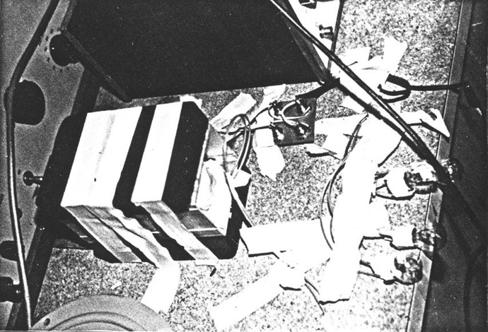
Ref: Floyd Sweet's VTA Generation One

Seen on the Square Board, wired into the Input, we see Stud Diode's in what appears to be a Bridge Rectifier.


Why is a Sinusoidal Waveform better?

If we apply a Sinusoidal Voltage waveform to an Inductor, we get a Sinusoidal Current waveform. The only problem is that we will have a Lag, sometimes a Lead in Phase angles of the Voltage and Current waveforms, in most situations.


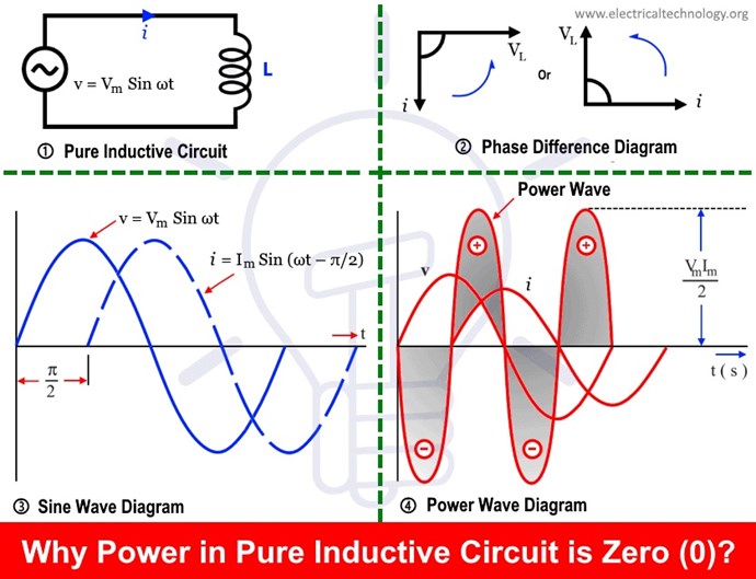
A Sinusoidal Current waveform, means we have a steady, even Change in Magnetic Field, which importantly is easily Controllable! By adjusting the Frequency of the Sinusoidal Voltage Applied Across the Input Coil, we therefore Control the Frequency of the Current Through the Coil, and in turn Controlls the Rate of Change of the Magnetic Field that the Partnered Output Coils are exposed to, instead of having a static, un-changing, Frequency in the DC Pulsed Coils.  

Of course, the Control we speak of is only down in the Audio Ranges, but its an area we really are better off working in! Ideally 50 or 60Hz would be perfect! That is the optimum goal as Floyd Sweet said:

The concept has merit but if pursued further R & D should be in the 60 Hz power frequency area.


Of course, we all should know by now, after years of posting and support, filled in my pages, Output Voltage:

Knowing that your Input Coil Does Not Generate your Output Voltage!


Your Partnered Output Coils "Generate" each others Voltage! This must be done using Faradays Law and the Variables:

  • ΔB
  • Δt


For those that do not know, or need a revision of Faradays Law:


E.M.FVolts = -N ΔΘB / Δt


Note: ΔΘB or Delta Phi B is just the Change of Flux of the Magnetic Field. Phi ( Θ ) is Flux, in the case Magnetic Flux. E.M.F is Measured in Units of Volts!

Don't over Complicate this, its very Simple, one needs to Load every Coil, this only works when we have Loaded Coils, as Current must Flow! Each and every Coil, when Loaded, must have a Current Flowing according to the Voltage that is "Generated", Ohms Law: I = V / R.

So if we use a Half Sinusoidal Wave, we can Control our Input and Control the Rate at which our Partnered Output Coils "Generate" their own Voltage, but only within the Ranges that your equipment can handle. At this point, your Output Current is virtually unlimited, it is the Result of the Potential ( Voltage ) and the Magnetic Fields you use ( Bucking ) to Pump Current!

Best Wishes,

   Chris

Order By: Standard | Newest | Votes
ISLab posted this 08 January 2023

I had to read it three times to get the full import of what you have shared.

Wow, Chris, this is brilliant!

You have opened a door that in one go: * Explains the Don Smith input diodes (the question you raised in the Don Smith thread), * Explains why Floyd Sweet did not need square wave pulses, * Frees us from the need for generating sharp pulses, * Allows for clean POC circuits without dangerous spikes and unreliable measurements, * Makes possible power output at conventional 50Hz while the coils still resonate at their high MHz natural frequency!

Again, wow!

I cannot wait to try out...!

ISLab posted this 08 January 2023

I had to read it three times to get the full import of what you have shared.

Wow, Chris, this is brilliant!

You have opened a door that in one go:

  • Explains the Don Smith input diodes (the question you raised in the Don Smith thread),

  • Explains why Floyd Sweet did not need square wave pulses,

  • Frees us from the need for generating sharp pulses,

  • Allows for clean POC circuits without dangerous spikes and unreliable measurements,

  • Makes possible power output at conventional 50Hz while the coils still resonate at their high MHz natural frequency!

Again, wow!

I cannot wait to try out...!

Chris posted this 09 January 2023

My Friends,

This is just one of many ways to trigger Partnered Output Coils!

The great Nikola Tesla used a Spark Gap:

Ref: Nano Second Pulses

Its just a case of getting the Rise over Run at an optimum point for the Magnetic Resonance of the Partnered Output Coils. Where your Partnered Output Coils Slap together with the highest efficiency!


The Frequency ( Rise over Run ) at which the Partnered Output Coils Slap together is what "Generates" the Output Voltage! 

Some ponderance Music for the Soul:


Best Wishes,

   Chris

Nurplex posted this 09 January 2023

ISLab said "

  • Makes possible power output at conventional 50Hz while the coils still resonate at their high MHz natural frequency! "


Does this mean you can get rid of the core and just use the natural resonating frequency of the coils like Don Smith has done?

Chris posted this 09 January 2023

Hello Nurplex,

Your Query:

Does this mean you can get rid of the core and just use the natural resonating frequency of the coils like Don Smith has done?


I believe so, there is no evidence to say that Air Cores wont work, my experience is, and I say with caution, I have had more luck with Cored Coils. I do not know the reason for this, other than we get a more Directed Flux Change in Time. This tends to give a better control over the working of the machine.

BUT, Air Cores should work just as good if my theories are correct.

Best Wishes,

   Chris

donovan posted this 09 January 2023

Hi,

In the RF world there are many circuits that will hit a tuned circuit with a pulse at a rate less than the resonant frequency with the result being a continuous wave of varying amplitude as the oscillations decay at the rate of the excitation pulse.  Most of the time they are harmonically related.

Mostly the relationship is not as extreme as 60 Hz to mHz.....

Donovan

Plasmonic posted this 09 January 2023

Hey Donovan,

https://www.toppr.com/guides/physics-formulas/beat-frequency-formula/

I wonder if maybe this is what we may be thinking to get lower frequencies from higher frequencies.


I'm not even certain this could be used directly in transformers or if this is only a signal thing meant to be amplified by solid state circuits.


Regardless I have a lot more to do before I go down this potential rabbit hole.  Maybe it's something to ponder for the future.  Though, I do expect great difficulty in maintaining a stable beat frequency in a resonating system, especially air core coils.


A simple pseudo circuit showing beat frequency traces.


I used a difference of 60Hz between the two AC signals which may not be correct for generating an 'equivalent' 60Hz AC (modulation?).  Like I said, too much to do before I worry about this further.


Matt

donovan posted this 10 January 2023

Hi,

Bang on!

In RF, it is common to "beat" two frequencies together (in a non-linear device) to come up with actually five output frequencies (if memory serves me);

The two input frequencies, the sum of the inputs, the difference of the inputs and DC.  And the non-linear device could be as simple as a diode.

I might have to get out all my old RF textbooks, this info may be useful here!!!

And of course when I talk of RF, I do not mean todays Software Defined Radios (SDR).....they are just computers.....RF with actual coils and capacitors.....is amazing.

Donovan

Chris posted this 10 January 2023

My Friends,

An Experimental Circuit to play with, one that is quite easy to control:

The small Inverting Circuit to the right, is meant to represent a Microcontroller that would control Q2 at the right time.


Where the Red wave represents every second Pulse. So your Input Coil only 'see's' the Sinusoidal Pulse where the Red Line is.

Now, this is a ways off the actual Idea! Its a start however! The timing needs to be done in the Microcontroller, not via a few badly configured Circuits and  CMOS Timer!

With any Input Sine Waveform, we have the ability to control a single Pulse into the input Coil, with all the right Rise over Run characteristics we need for the Machine to Operate. Please remember, at the moment, this is experimental and may work out to be problematic when returning Power to the Input, lets see...

Best Wishes,

   Chris

donovan posted this 14 January 2023

Hi,

I am better at putting together circuits, than programming.  So, I have prototype circuit for a Single Shot Sine Pulse System.  Should I post the photos and notes on this thread, or start a new one?

Donovan

Chris posted this 14 January 2023

Hey Donovan,

You can post here is you wish? I will help you with a Microcontroller if you need help.

Best Wishes,

   Chris

donovan posted this 15 January 2023

Hi,

I have been thinking about using a pulsed 60 Hz sine wave on my POC transformer for a bit, and when Chris started this thread....well....

Like a lot of prototypes, I dream about it for a bit and then throw something together with what I have laying around.  The POC transformer I built used a core from a big battery charger, and 18 ga wire, so it is beefy.  For the Single Shot Sine Input transformer, I grabbed an 8 Vac, at 2 A transformer.  so a little bit of a mismatch...

I just used a 12 Vdc supply to power it.

In the video, I mention, it's an analog circuit.....well, analog/digital....simple.

This first build, and initial test, was on a Friday night.....so more testing may be required!

The schematic I settled on.

The BreadBoard build up.


The Input to the circuit from the 8 Vac transformer, and the MOSFET Gate Drive from the timing circuit. Not connected to the POC XMFR, so Unloaded.

Input Vac, and the Gate Drive, under load.  My POC XFMR is a heavy load at 60 Hz......

Input Vac, and L1 current.

Input Vac, and L2/Lamp Current.

Input Vac and L3/Diode Current.

It is NOISY!

All input is appreciated!

Donovan


donovan posted this 15 January 2023

Hi,

I did have a short video.....just trying to figure out how to upload it......

Anyway, the video was showing how the adjustment worked.......I can adjust the single pulse from, every cycle to about every 30th cycle.....

I see on my Scope images, that the input Vac from the tramsformer has "crossover" distortion on it.......may be artifacts from a poor transformer.......or, I live off grid.....maybe its from my inverter....I never scope'd that before....

My incentive to keep working on Above Unity Machines......is.....I don't really have a backup generator.....Just a little Honda, to top up the batteries, in the winter, when there is not enough hours of sun.....I like to wake up, in a cozy bed!!!

Donovan

Chris posted this 15 January 2023

Hey Donovan,

Please see: Help with using the Forum.

This gives all detail on using the forum!

Good work, only thing I can suggest is to observe Polarity of Asymmetrical Regauging:


As your Asymmetry of the Regauge Period is important, as is the Polarity.

Best Wishes,

   Chris

donovan posted this 15 January 2023

HI,

Yes, the concept of "asymmetrical regauging" has not become "second nature" for me yet.

Donovan

ISLab posted this 16 January 2023

Donovan:

In the RF world there are many circuits that will hit a tuned circuit with a pulse at a rate less than the resonant frequency with the result being a continuous wave of varying amplitude as the oscillations decay at the rate of the excitation pulse.  Most of the time they are harmonically related.

Mostly the relationship is not as extreme as 60 Hz to mHz.....

As far as I understand, what Chris has shared is much simpler. There is no attempt to derive a lower F from from higher F.

Rather the coils resonate on their own at their high F. But the Sawtooth Wave (formed by that resonance) is pulsing at a much lower F of ideally around 50Hz (or double). So that we get clean pulses of energy at conventional and manageable frequency.

The single pulse needs to be quarter wave of the POC natural F. (Or perhaps one could even try a train of these pulses to build up magnetic fields.) Then a much longer pause (assymetric reguage) during which we extract the Sawtooth Wave generated from the POC.


Nurplex:

Does this mean you can get rid of the core and just use the natural resonating frequency of the coils like Don Smith has done?

From what I understand of the theory, the problem of natural resonance without cores is that the F is too high and so the entire circuit needs to be much more accurate and the coil shapes and wire lengths much more precise to avoid reflections or other transmission-line issues. Hence, Don Smiths advice to "make it beautiful and it will work". As also Donovan's comment that the professional broadcast equipment he worked with were "works of art". The benefit or air-core, though, is that calculations for frequency and resonance are far simpler, and so easier to tune.

Inserting the core drops the resonant F, and makes the construction far more tolerant of flaws. The complication is that now the calculations are far more complex as core permeability is not exactly known, is uneven across the coils, and varies with each layer, and multiple resonances  such as LC, antenna length and core magnetic currents have to be aligned for maximum resonance.

This is as far as I understand. Perhaps there is more. Or less.


Donovan:

Yes, the concept of "asymmetrical regauging" has not become "second nature" for me yet.

I hope you are not confusing between Asymmetric Reguaging (which you already have ) and Asymmetric Coil inductions.


I'm very impressed with your circuit and initial experiment! Congratulations!

You have a 1:4 assymetric reguage. Perhaps raising the pulse voltage might increase this?

What about your coils (length, turns, ratios, core, placement)? Perhaps you can share more about them for feedback?

Wishing you good progress!

donovan posted this 16 January 2023

Hi,

Great comments!

In the RF world the excitation pulse of a resonant circuit would always be harmonically related.......and in many circuits there was a stable phase relationship as well.

In my initial circuit the regauge ratio is adjustable from 1:1 to about 1:50, and is strickly determined from the monostable adjustment.

Just off the top of my head, I used an "E" core (Steel), with 18 ga wire, L1 = 15 T, L2/L3 = 60 T.  L1 over top of L2.

When it comes to coils and air cores.....everything has its place.....at high power levels in the AM radio band (540 kHz - 1.6 mHz), most coils are air core.  But they may be 1m talll and .5m in diameter.....easy to work on!

And I have to say something about resonance.....I have seen a lot of comments here about how hard it is to get resonance.....In my mind it has always been easy to make something resonant.....just, is it on the frequency you want, and is it stable, and is the impedance right, is the bandwidth right, etc....The ratios of XL/XC to R plays a big part....

Donovan

Chris posted this 16 January 2023

Hey Guys,

This is great to see! Good solid discussion, and discussion I myself have also gone through.

Ignoring the Regauge period for a minute, ISLab is correct, the Input Frequency is Phase Locked to POCOne and POCTwo to POCOne with a Delay in Conduction. So from Input Coil Mosfet TOn there is a delay in Conduction to POCTwo.

Electromagnetic Induction occurs twice in Asymmetrical Electromagnetic Induction Machines, Once between Input Coil and POCOne, and a second time between POCOne and POCTwo!

At Magnetic Resonance, the Delay is minimal and we also have maximum Currents, approximately equal in Amplitude.

When the POC Currents are approximately equal in Amplitude, your Input Current is at minimum! Because you have an Assistive Force, Assisting the Input Coils Current.

If POCOne and POCTwo Oppose each other, then one MUST Assist the Input Coil Right? Maximizing this assistive Force is key to making this work!

This is really easy and very cheap if one thinks about this the right way!

Best Wishes,

   Chris

donovan posted this 17 January 2023

Hi,

Yes, this is great!

In tech school, I graduated top of my class......that was a long time ago now.....seems like yesterday....I think my picture is still on one of the walls of the main hallway in the electronics building.......anyway....I actually liked helping other students study.....answering their questions and explaining concepts to them, always made me understand them better myself!

Your last post on delay, phase and currents, helped me understand this concept better.

And you comments on currents.....reminded me of resonant tank circuit design in the big transmitters.....these tank circuits "looked" over built compared to the output power.......until, you realize that the "circulating" currents in tank circuits would be many times higher than the output current.

Sharing all of our knowledge, is very useful.

Donovan

donovan posted this 23 January 2023

Hi,

I am looking for feedback on some of my thoughts on this subject......on comparing the single pulse of 60 Hz to the low duty cycle higher frequency of the sawtooth waveform to the operation of a sparkgap.....

Observations of various experiments:

1) the self resonant frequency of our coils seem relatively high, compared to 60 Hz.

2) the regauging waveform is a low duty cycle, higher frequency waveform (higher than 60 Hz, yet much lower than the self resonant frequency.) 

3) it seems in the low duty cycle waveform during the on time, the L1 di/dt is governed most by the inductance of the coil.  We see the tau of the current during this on time, and we see some managable self resonant voltages of a higher frequency.  When the input voltage is turned off, we see a much faster di/dt present on the coil, and we see large (dangerous) self resonant voltages.

4) compared to ......my Single Shot Sine Pulse experiment.....where the L1 di/dt seems primarily governed by the shape of the sine pulse.......until, if you notice....when the MOSFET is turned off (and with the present circuit, this would happen when the input voltage of the sine pulse would be about 1 Volt) and we see a much faster  di/dt.  And it appears in my experiment, the regauge on L3/Diode happens during this time......

5) it seems in a Spark Gap system (as pictured in an above post), as the Sine pulse rises, the capacitor is charged, when the Spark Gap conduction Voltage is reached, and it conducts, all the capacitor voltage is presented to the coil, and the coil di/dt comes into play we have maximum self resonant voltages happening, and as the input sine (capacitor) voltage falls off we have more, but safe self resonant voltages.

Ideas from these observations:

1) It seems the spark gap is the perfect switch for what we are looking for.

2) It seems most MOSFET switching systems are just the opposite of the spark gap.

Next experiment to try:

1) modify my control circuit to turn on the Sine pulse only from 90 degrees to 180 degrees, to simulate a spark gap.  This would present an instant voltage to the coil to let the coil di/dt to work, while having a slowly falling (sine) voltage towards turnoff which would limit dangerous voltages.

I think I got all those ideas presented as I imagined them!  Any input is appreciated.

Donovan

  • Liked by
  • Chris
  • Augenblick
Chris posted this 23 January 2023

Hi Donovan,

Yes, you're mostly on track!

I think you need to think in terms of Variable AC Frequency and not just 60Hz! POC Might be Resonant at 30KHz, as you point out, not 60.

I hope you get what I am trying to share, its got to be Variable, it cant be fixed Frequency.

Yes, once we get the Specification Specifics 100% on target, we can then predict it, at the moment its a frequency that must be "Found".

You have a very good understanding, and you have a very good post there. Yes, the Tesla Style setup could be used:


Where the Input AC Signal could be a Flip Flop LCR Resonant driven by a Pair of Mosfets driven by G:


Each Experiment teaches us what we need to know. The answers we seek are found on the Bench, in the Lab!

Best Wishes,

   Chris

We're Light Years Ahead!
Members Online:

No one online at the moment


What is a Scalar:

In physics, scalars are physical quantities that are unaffected by changes to a vector space basis. Scalars are often accompanied by units of measurement, as in "10 cm". Examples of scalar quantities are mass, distance, charge, volume, time, speed, and the magnitude of physical vectors in general.

You need to forget the Non-Sense that some spout with out knowing the actual Definition of the word Scalar! Some people talk absolute Bull Sh*t!

The pressure P in the formula P = pgh, pgh is a scalar that tells you the amount of this squashing force per unit area in a fluid.

A Scalar, having both direction and magnitude, can be anything! The Magnetic Field, a Charge moving, yet some Numb Nuts think it means Magic Science!

Message from God:

Hello my children. This is Yahweh, the one true Lord. You have found creation's secret. Now share it peacefully with the world.

Ref: Message from God written inside the Human Genome

God be in my head, and in my thinking.

God be in my eyes, and in my looking.

God be in my mouth, and in my speaking.

Oh, God be in my heart, and in my understanding.

Your Support:

More than anything else, your contributions to this forum are most important! We are trying to actively get all visitors involved, but we do only have a few main contributors, which are very much appreciated! If you would like to see more pages with more detailed experiments and answers, perhaps a contribution of another type maybe possible:

PayPal De-Platformed me!

They REFUSE to tell me why!

We now use Wise!

Donate
Use E-Mail: Chris at aboveunity.com

The content I am sharing is not only unique, but is changing the world as we know it! Please Support Us!

Thank You So Much!

Weeks High Earners:
The great Nikola Tesla:

Ere many generations pass, our machinery will be driven by a power obtainable at any point of the universe. This idea is not novel. Men have been led to it long ago by instinct or reason. It has been expressed in many ways, and in many places, in the history of old and new. We find it in the delightful myth of Antheus, who drives power from the earth; we find it among the subtle speculations of one of your splendid mathematicians, and in many hints and statements of thinkers of the present time. Throughout space there is energy. Is this energy static or kinetic? If static, our hopes are in vain; if kinetic - and this we know it is for certain - then it is a mere question of time when men will succeed in attaching their machinery to the very wheelwork of nature.

Experiments With Alternate Currents Of High Potential And High Frequency (February 1892).

Close