Reliable and Flexible Switching System

  • Topic Is Sticky
  • 9.7K Views
  • Last Post 21 February 2024
Chris posted this 30 September 2017

A Reliable and Flexible Switching System is second to none, it is the most important piece of Hardware one could have on your bench!

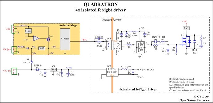
I was lucky enough to share some data with a friend that had worked on this same concept with one of his friends, Back then, the idea was called the: Quadratron
 

Funny enough TheOldScientist has done some videos on this:


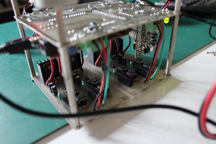
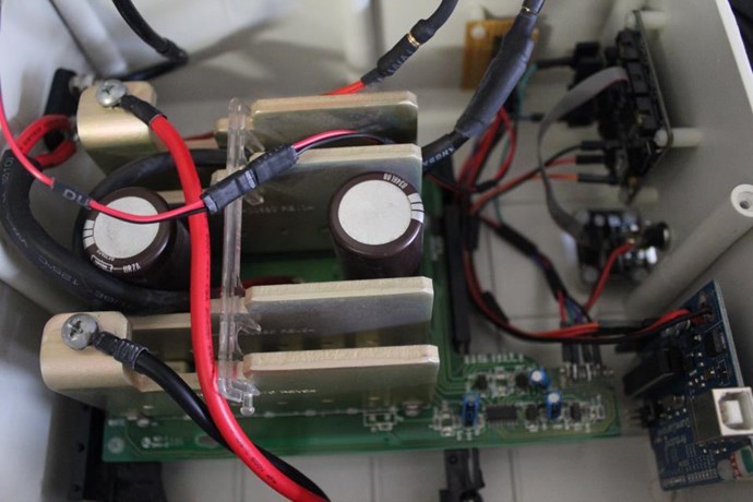
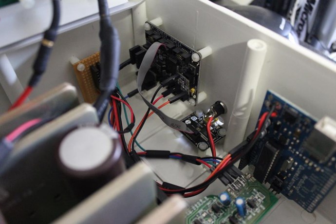
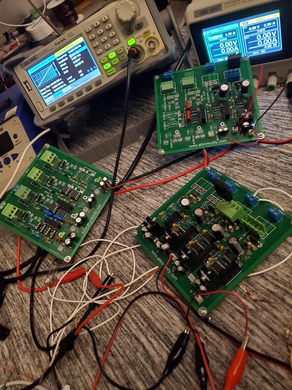
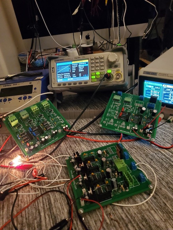
I have also build a few versions of my own inception of the: Quadratron which is now called IPC-quadra


Version One:
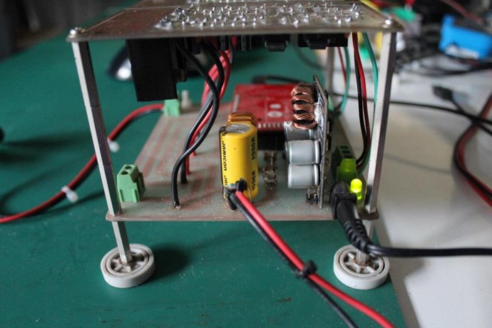
 

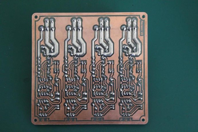
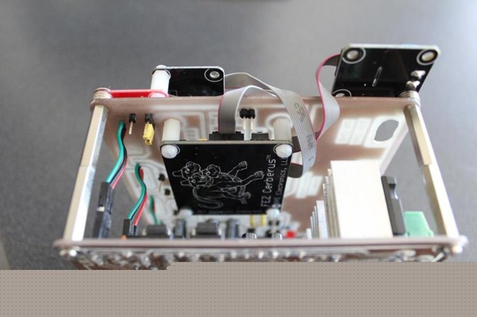
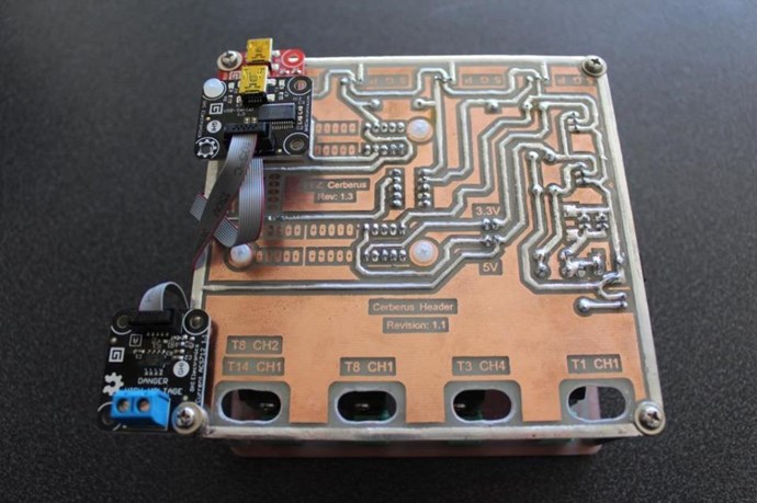
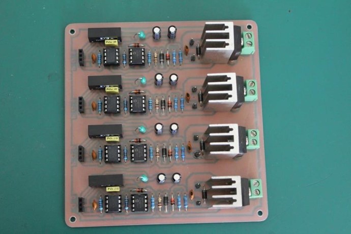
Version Two:


I have another H Bridge I use also, this is not related to the Quadratron. It is a Custom Built, Salvaged from an Old UPS, 3000VA:
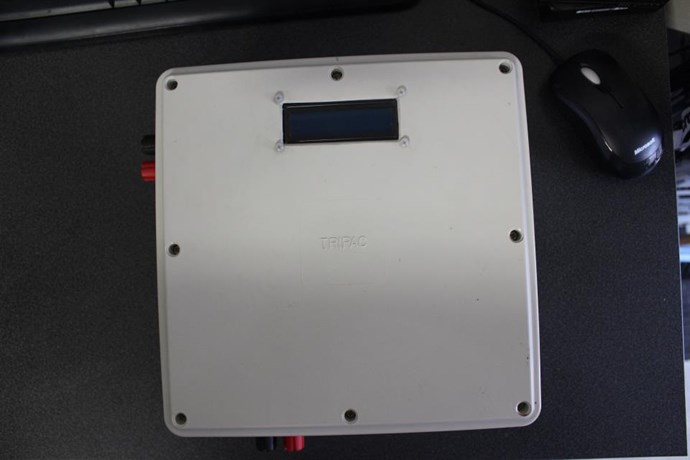
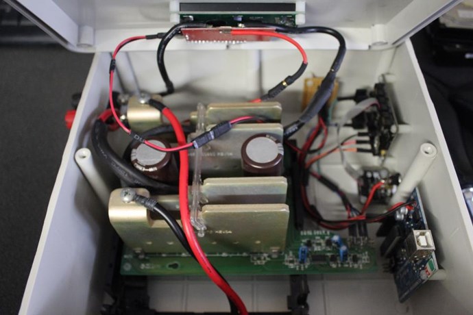
 

I think it is important to not, this is very handy, but its not a necessity, cheaper and easier options exist. EBay has some good options. Variable Frequency and Duty Cycle are the absolute most important.

High Voltage and Current is not necessary.

I personally find a Microcontroller is a good cheap option! Easy to use, Plug and Play if you don't mind the pun! I have built all my own software:
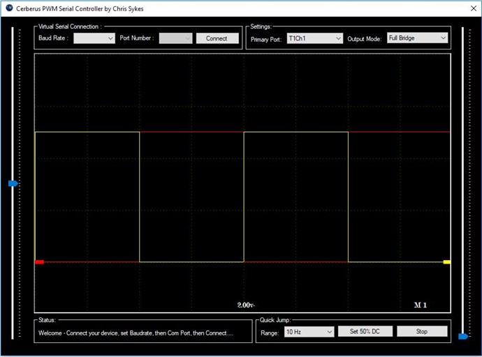
 

I think if we combined our skills, we as a team could come up with a community based project that is better and cheaper than all options presented!

China could do cheap PCB's, We could build our own software!

We could find a cheap Microcontroller.

Let me know if you're keen to look into this!

   Chris 

Order By: Standard | Newest | Votes
Chris posted this 21 January 2020

Hey Jagau,

It is, my friend, AR on the original Circuit, gave me the circuit, I made a few small changed, but it is the best I have ever seen when it comes to Isolation and Speed and Bandwidth.

Some of my earlier Circuits had some small mistakes / Imperfections, but this last version is by far the best I have built!

I have already started a new version, it has a few improvements, Double sided on some High Current Traces, shorter Traces where possible, moved the Decoupling caps closer to the IC's, better size, a little smaller, and little better cutout, around the outside:


I really enjoy prototyping stuff like this, not sure if much more improvements can be made here on in.

   Chris

Jagau posted this 21 January 2020

Hey Chris

Sounds interesting but just out of curiosity is it the same initial circuit component to the one I made?

Jagau

Chris posted this 21 January 2020

Hey Jagau,

Yes same basic circuit.

   Chris

  • Liked by
  • cd_sharp
  • Augenblick
Chris posted this 22 January 2020

Hey CD,

You will be fine to use something close.

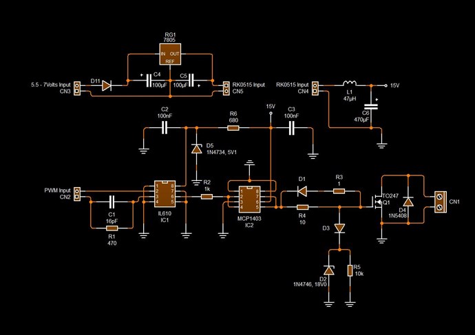
C3 16pf is a Filter Cap, to try to filter out anything that is not desirable. At least this is my understanding. Jagau can likely explain better the use here for this cap.

The value is not all that important, just use something that is close.

I cant wait to see all your builds!

   Chris

Jagau posted this 30 January 2020

I apologize I had not seen your question, I hope it is not too late.
As said the manufacturer and I quote:


  For high-speed logic signals (tr, tf <10 ns), a 16 pF capacitor is recommended. But the capacitor value is generally not critical; if in doubt, choose a higher value.


I personally use a 20 nf

Sorry for the delay


Jagau

Chris posted this 17 February 2020

My Friends,

I see more and more, in need for a Reliable and Flexible Switching System.

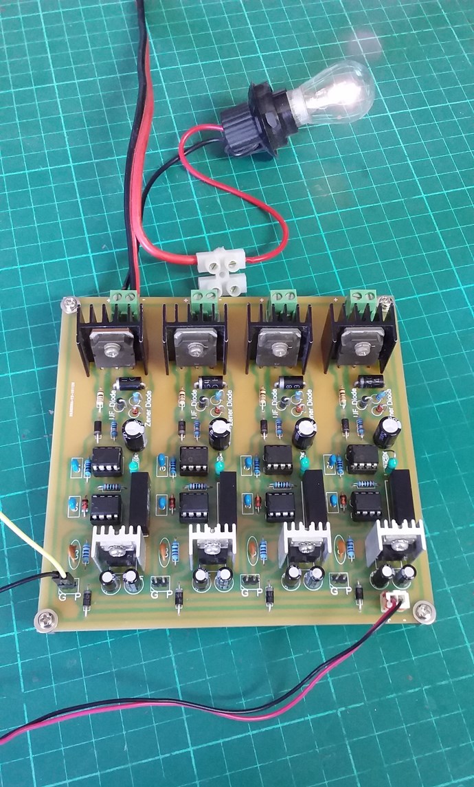
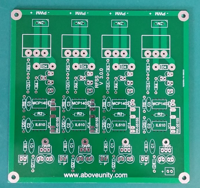
We are now up to version 3.0 of the Reliable and Flexible Switching System, version 2.0 seen here:

I would really like to see more results / experiments of those that have received their free PCB's!

It would be great to see more use of the PCB's! They are very useful Circuits!

Best Wishes,

   Chris

Jagau posted this 17 February 2020

Mine is completed and it is going very well I am satisfied.
I'll give you a demo soon to show it to you.
I am, as you know, completely absorbed by another project that exceeds all my expectations.
Thanks for the board
Jagau

  • Liked by
  • Chris
  • Augenblick
Chris posted this 17 February 2020

Hey Jagau, CD, Awesome! I am happy to hear!

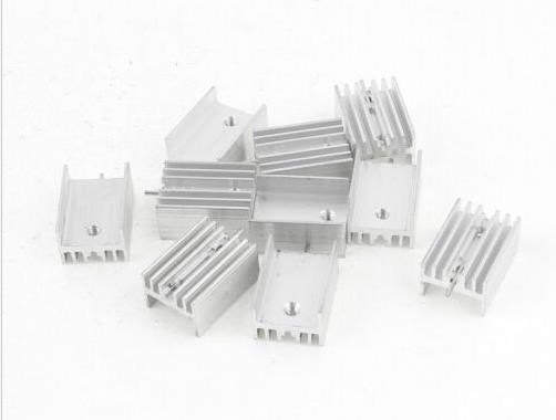
@CD, for proper Isolation, the Regulators and Mosfets should not use the same Heat Sinks. The Collector Tab, or the Drain Tab will effectively parallel the Circuits to Ground. A PCB Mount TO 220 Aluminum Heat Sink Heatsink can range from $0.70 to $3.00 or more. I use the cheap ones, they seem to work just as good:


Just a heads up my friend. I hope this helps some. There is some heating, a 12 volt to 5 volt dissipation will create some heat. Bigger Heat Sinks are better, or drop your input Voltage.

Best Wishes and Thank You for sharing your progress, I very much appreciate!

   Chris
Jagau posted this 25 February 2020

Hi chris


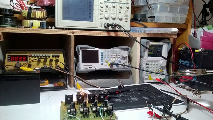
I started to experiment with the card I received. As you can see on the scope shot, the insulation is excellent, even better than I thought. No distortion on the input signall on channel 1,  compared to the output signal channel 2, excellent.


Regulation with a minimum input voltage of 7.5 volts, this is what the 7805 needs to regulate well, is perfect,  which gives me a very precise 5 volts even with the lamp on


thank you again many other projects in mind with this card.


Jagau

Chris posted this 25 February 2020
Hey Jagau,

Thats excellent! I am very pleased to hear youre so happy with the PCB.

It is one of the best Circuits I have ever used! By far! It is very precise and very reliable. Of course the components installed, Mosfet and so on does make a difference also, but the general circuit is first class!

I am so pleased to hear! Thank You for letting me know!

Best wishes,

Chris

Andrew posted this 05 March 2020

For those of us without the necessaries (ability, time, space) to build such a thing of wonder, would an off-the-shelf variable frequency drive/inverter be suitable for pulsing the primary coil? Or is there something else you'd recommend? I'd like to build my own when the time is right, but I'm itching to start experimenting asap...

Vidura posted this 05 March 2020

Hey Andrew and welcome. There are options to buy PWM units of the shelf, most important is frequency and duty cycle adjustment. I personally prefer the analogue version, and if the on time can be adjusted independent from the frequency is helpful in many experiments. For Switch and driver you can make yourself a simple setup, for low side switching. Feel free to copy designs from the thread "developing a modular switching tool for research", Or contact me if you need assistance. Vidura.

Chris posted this 19 April 2020

My Friends,

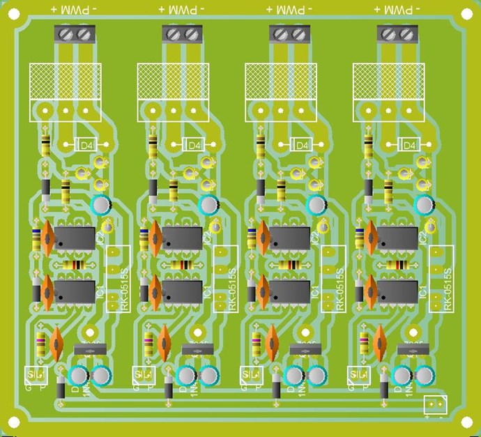
It is early days, not much testing has been done, but V3.0 of the 4 Channel Isolated Mosfet Driver Board is on E Bay.


Note: This is a PCB Only.


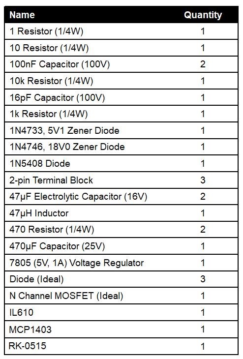
The MCP1403, is no longer stocked at element14, a chip with the same Pin Out and characteristics will need to be sourced, or another supplier will need to be found. I managed to find some at Mouser Electronics. The opposite is true for the IL610. The RK-0515S is easy to find still. Be careful of the layout, don't purchase until you have checked the sizes. I am sorry, I don't have enough to share.


Single Channel list, x4 to get 4 Channel:


Version 2.0 I have tested thoroughly, version 3.0 has not been tested so much. These PCB's once assembled and working properly, are worth their weight in Gold! See the above testimony's!

Anyone not having an Electronics background, I do not recommend purchasing, these are fairly involved to put together!

For beginners, I would recommend purchasing Vidura's Switching Module, Vidura's units are ideal for those that do not have a great Electronics Background. Please contact Vidura for more help.

   Chris

baerndorfer posted this 26 April 2020

a short question here...

if i control the switching of a circuit with a microcontroller - Arduino for example - i have to deal with the 16MHz frequency.

actually i can do a pulse with my circuit which is 126ns long (PulseWidth). the controller has to switch ON and OFF - therefore he will need 2 clock cycles. Because i have a 16MHz chip i can calculate the time for one cycle which is 64ns.

if my thinking is correct (is it?) i cannot go under this time value right?

regards!


Chris posted this 14 June 2020

Hey CD,

My Friend, I am sorry I do not know and there are no apparent ID Codes on them. I scavenged them from old Circuit boards.

Best wishes, stay safe and well,

   Chris

  • Liked by
  • Augenblick
  • cd_sharp
Ourbobby posted this 02 August 2020

Hi Chris,

From above reply,

"It is early days, not much testing has been done, but V3.0 of the 4 Channel Isolated Mosfet Driver Board is on E Bay."

Not listed anymore, who might have them?


Regards

ourbobby

Chris posted this 02 August 2020

Hi Ourbobby,

Sorry, I don't sell them anymore. The cost per unit was to high and I just could not make it affordable and worth while.

Best wishes, stay safe and well,

   Chris

sr73 posted this 21 October 2020

hi Chris,


any chance you will make those pcbs again, some of us I can pay you the cost + your profit.


thanks,

Sam.

Chris posted this 21 October 2020

Hi Sam,

I will look into it and see what I can do the PCB's for. I have had a few inquiry's lately.

As much as anything else, Postage is what makes this unaffordable, it is super expensive to post anywhere now from Australia! I think Australia post have made post unaffordable.

Best wishes, stay safe and well,

   Chris

sr73 posted this 21 October 2020

Hi Chris,

I hope you're on the mend, and I hope those injuries you mentioned are not too serious.

Please let us know how mush is the cost of shipping, and i'm sure some of us will take that into account.

In the meantime, i'm trying to find a starting point here to start my experimentation, wow this site is very extensive, but thanks for putting up for us.


Kindest regards,

Sam.


Chris posted this 26 October 2020

My Friends,

Australia Post is not reliable enough or cheap enough for me to continue selling PCB's.


At your own risk, no responsibility on me:

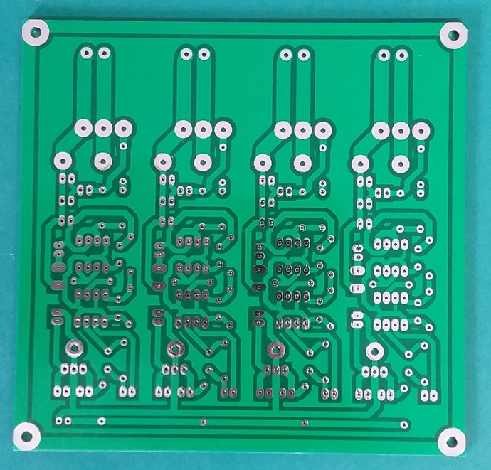
I have decided to post the zip file of the gerber and drill files.


What you will need to know:

Dimensions: 126mm x 122mm

File: .gb0 -  Board outline layer

File: .gb1 -  Bottom copper (solder side) layer

File: .gb2 - Top copper (component side) layer

File: .gb3 - Bottom (solder side) solder mask layer

File: .gb4 - Top (component side) solder mask layer

File: .gb5 - Silk screen (component outline) layer


I have used JLCPCB and they are great, just upload the zip file and add the above into the instructions. They need to know what each file is for. Beware the cost, $2 PCB is not what you get because of the size and shipping.

This is given freely, but I take no responsibility from here what you or others do with it. Design V.3.0 is now Public Domain.

Best wishes, stay safe and well,

   Chris

Attached Files

Jagau posted this 26 October 2020

Hello Chris

You have a lot of compassion and a big heart my friend.

I think it will help a lot of people who haven't had the chance to have it, it is a real gift.


Thank you


Jagau

Chris posted this 26 October 2020

Hey Jagau,

Thank You My Friend!

We have nothing, if we don't have each other. I want the Human Race to succeed with all my heart!

Best wishes, stay safe and well,

   Chris


Chris posted this 04 November 2020

My Friends,

NOTE: I do not consider Itsu a Troll or a Trouble maker! He posts with Trolls and Trouble Makers. Itsu is a hard worker and does excellent work. I do not consider Verpies a Troll or a Trouble Maker either.

Some news:

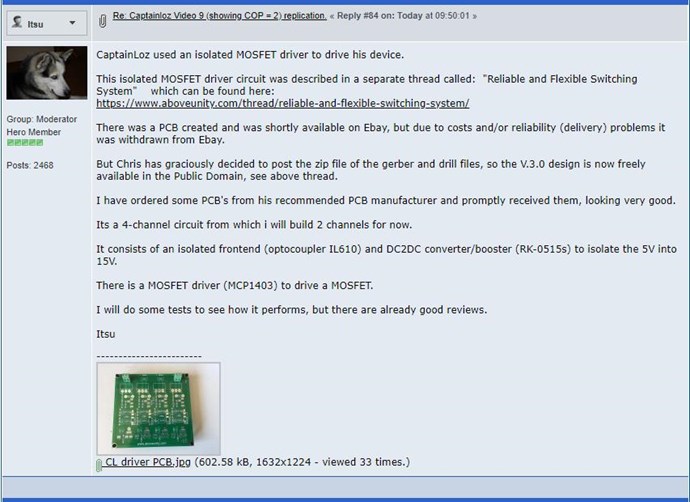
Ref: Captainloz Video 9 (showing COP = 2) replication


They will be doing one of two things here:

  1. Genuinely building the RFSS and testing it, and attempting to use if for their experiments. To benefit from.
  2. Building it to try their very hardest to find a fault that they can use to explain where all our Success comes from. Let them Try! We know better!


Note To Itsu: If you Succeed, I would not go public on the Forum you currently post! You will see what you think of as your friends, turn against you, attack you and make you feel less than 1 inch tall! They will Troll you like you have perhaps not seen before! So, a friendly Warning, be very careful what you say and where you say it if you don't want Trouble from you so called Friends!

It is very hard to trust the Haters, the ones we have had so much problems from in the past!

Best wishes,

   Chris


P.S: The IL610 is not an Optocoupler, it is Giant Magnetoresistive (GMR) technology, or you could say a magnetocoupler. Not an Optocoupler! The difference is about 50MHz!

Forushani posted this 05 November 2020

Hi Guys


thanks for the board file Chris.

Since I am not good at soldering, I am going to see if I can order a finished board.


Is there a BOM file?

I don't know enough to make one as I don't know like voltages for capacitors, etc?


thanks 

  • Liked by
  • Chris
  • Augenblick
Chris posted this 07 November 2020

Hi Forushani,

No, no BOM files, just what's in the zip file.

Best Wishes

   Chris  

Pierre Sinclaire posted this 08 November 2020

Thank you Chris for the file. 

Forushani posted this 09 November 2020

I ordered some boards.

I will have some boards and am willing to give them away. You just pay shipping .

I will give 1 board to anyone that can put together a good BOM file and pay the shipping in the US.

The other 4 , I will leave to Mr Chris to decide who should get them.

Any suggestions? Anyone else inerested?

Chris posted this 09 November 2020

Hey Forushani,

That is a very generous gift to others!

Please organise via PM. It is best if you decide who gets the boards.

I wish I saw this sort of interest back when i was doing this, many now see the worth of such a simple thing! Its great to see! One of the most important tools in the belt of a Serious Researcher! A Flexible and Reliable Switching System!

Best wishes,

   Chris


P.S: Re the BOM file you asked for or Bill of Materials, is on this thread in a few places, one is Here.


Forushani posted this 11 November 2020

Thanks Chris,

.You have done so much for the community. I am offering to assist in any way possible. I am just starting out as a beginner and can appreciate all the hard work others have done that can be a good foundation for the rest of us.

Thanks again and God bless you

  • Liked by
  • Chris
  • Augenblick
Forushani posted this 12 November 2020

Sorry for all the questions

What MOSFETs do I need?

  • Liked by
  • Chris
  • Augenblick
Chris posted this 12 November 2020

Hey Forushani,

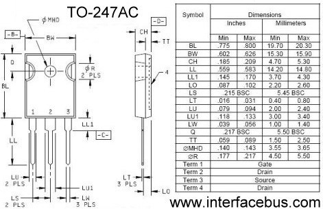
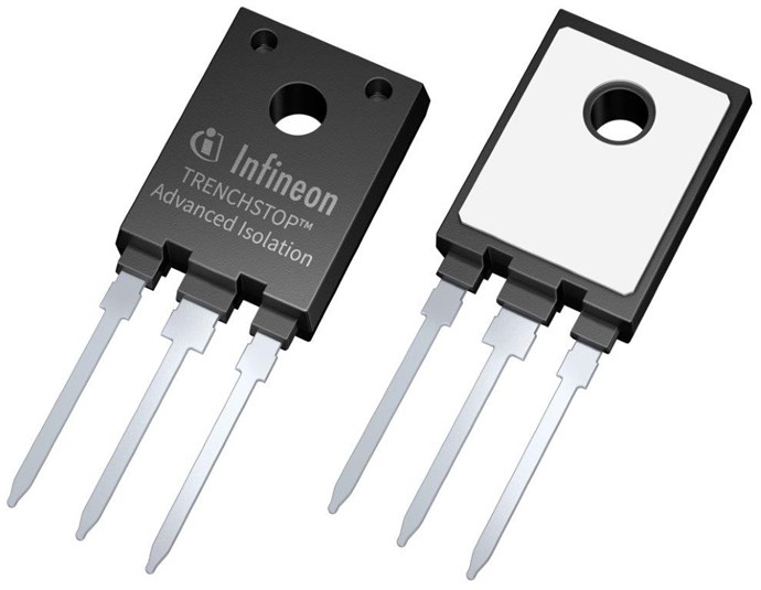
The Package Type, for the PCB, is a TO247 or similar:


There are many very good Mosfets on the market. We have some discussion Here and Here.

There is some information on this thread also.

A Low RDSON is very desirable! 0.05 or less would be nice, Matching Voltage Current Rating is also important.

I hope this helps!

Best Wishes,

   Chris

Forushani posted this 19 November 2020

Thanks Chris

Having a hard time sourcing the IL610.

Also, can I get some specific diodes to use for the fast diodes?

Any particular one you guys used.

  • Liked by
  • Chris
  • Augenblick
Chris posted this 19 November 2020

Hi Forushani,

The IL610 can be found here. I have given all this above btw.

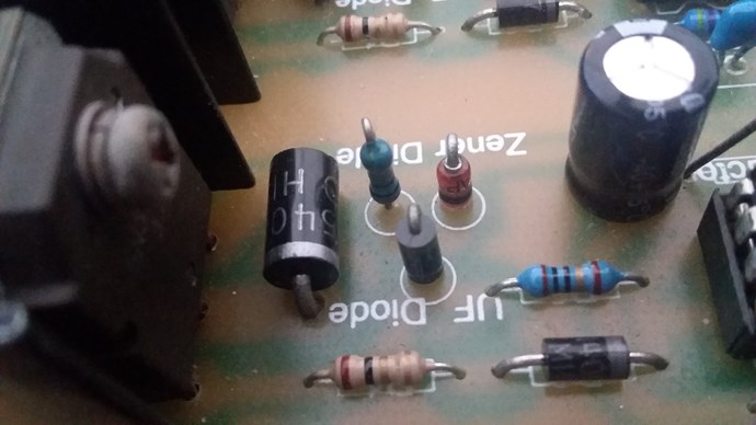
Just find the best diodes you can, mine: IN5408, IN4004, but use UF Diodes if you can, I have in some of my builds. Also18V Zener on the negative Rail:


Have you got the Zener Diodes in Place? They are for Mosfet Protection.

Best Wishes,

   Chris

Chris posted this 21 November 2020

Hey Forushani,

Very Nice! Thank You for Sharing!

Best Wishes,

   Chris

Forushani posted this 21 November 2020

Dear Chris,

Do you think those Diodes D1, D2, D3, D4 by

"www.aboveunity.com"


should be same or different markings?

What about my MOSFET selection? Any good?


Thank you sir

Chris posted this 21 November 2020

Hello Forushani,

All the same, they are just Power Protection Diodes. To ensure the Power Supply is protected.

Best wishes,

   Chris

Chris posted this 24 November 2020

Hey Forushani,

You some how inverted your Images Horizontally, it looked like your Diodes and a few other components were in wrong, but taking a closer look, I see you invert your Images Horizontally.

NOTE To Other Readers: Beware, this Inversion!


Other than the Images being inverted, its looking good!

Good Luck!

   Chris

  • Liked by
  • Augenblick
Forushani posted this 24 November 2020

the only difference as far as I can tell, comparing your board and mine is


looking at my board, I have resistors, capacitors, then chips 

on yours you have caps, resistors, Chips

but I followed the board layout.

I figured this is version 3.0 but the other one might be an older version.


If this is not right, please advise.

thanks


  • Liked by
  • Chris
  • Augenblick
Forushani posted this 24 November 2020

Couple of more questions


The board has a single power input and 4 Signals, one for each channel. Correct?


Also, what was the minimum and maximum voltage and amperage please?


Can one use the board for negative voltages down the road?


Thannks guys


Chris posted this 24 November 2020

Hey Forushani,

Its looking good! Follow the Circuit above and check the Parts are 100% right.

Check your 5v zeners, 18v zeners and polarity on the Input.

Looking good well done!

Good Luck!

   Chris


P.S: Yes 4 Chanel if you keep Mosfets Isolated. One power Input, 7-12V. Make sure all polarity's are right! Check Diodes on the Board etc...Use a 10 Amp Fuse. Board can handle more, but no point going crazy silly with it! Use it well within Mosfet Ratings!

Chris posted this 25 November 2020

Hey Forushani,

Did you solve the problem? From the first post you said its not working, and the second post I see a Square wave, did you figure out what the problem was? Also you are using Current on the PSU.

From what I can see, its working, you have scope on the Output, you have waveform, it appears to be working to me? Yes?

Anyone in this situation should always probe the Mosfet Gate, see if there is Signal, and what Amplitude the Signal is!

If there is Signal here, it should be working! If not: Check all components, make sure you have everything Correct! Diode Polarity's, Integrated Chip Polarity's, everything!

Work back to where you DO have a signal and Id the problem part. Place something incorrect, it will likely blow something, gotta get everything 100% Correct.

Best Wishes,

   Chris

  • Liked by
  • Augenblick
  • ISLab
Chris posted this 25 November 2020

Hey Forushani,

Excellent! Good Work!

I am very pleased you now have it working! There is a lot of things you can do with this very good PCB! We have many threads here that you can learn about Switching, and Wiring Configurations.

Start here: On and Off, Conduction in a Mosfet, and work on the: Measurements also if you wish. Lots of excellent information in there.

I like the Quote: Little Steps for Little Feet - Sir Richard Feynman

No Pressure, no stress.

Best Wishes,

   Chris

  • Liked by
  • ISLab
  • Augenblick
Forushani posted this 10 December 2020

Hello everyone,

I told everybody that I was a beginner and did not know a thing about electronics and I still don't.

So, I ordered some boards from China and a few things from Mouser to build the board.

My first board was really hard for me as I had not soldered anything before. Took me awhile.

When I started testing. I thought the board did not work. I checked and double and triple checked everything and my light bulb was not lighting.

So, I said to myself this board is ducked up. Let's bud another from scratch. Off I went buying the 2nd board. That did not work. How petty. Is it the board or parts or my skills or there lack of.

So, guess what. Let's build one from scratch Third board and I am running out of chips and capacitors and diodes and more orders.

Tonight, with Chris's and Captains (Great Man), I realized the problem.

This is not to provide the power but rather the switch. Now, I understand. I was trying to light the bulb with the board.

My bad guys. Beginner mistakes are expensive but somehow I thought, I was going to have some beginner luck.

I hope you guys are not laughing too hard . I will not quit at small hurdles.

Thank you for all the help and the fun I had making these boards. .now, off to making bigger (costlier) mistakes. By the way, can somebody tell me so.e creative thing to do with 3 QUADRATRONS . Does this quality as a DOZENTRON maybe?

  • Liked by
  • Augenblick
  • ansen
Forushani posted this 10 December 2020

Chris posted this 10 December 2020

My Friends,

I want to post this, some Private Message Help, here, in the hopes it helps others:


If you have any problems

Follow 100% the Circuit:


Yes, the board should always work! The only time it wont work is if you have:

  1. Faulty Part.
  2. Have something wrong, either Diode back to front, incorrect Mosfet, incorrect part somewhere.


I have never seen a bad PCB, but that's also a remote possibility. Check the PCB's against each other. Most of us here, have the same PCB, all here have had no trouble with it, so best advice I can give is check all parts, make sure all parts are right, check all are working, no bad parts, check your Mosfet is within the Ratings, 10 to 20Volts Max on the Input, make sure your Mosfet's are NPN, make sure they are NOT PNP. We don't use PNP, they are not very forgiving in my opinion. Got to be NPN.

Follow 100% the Circuit, and select a Mosfet within rating, and it will work.

Probe with your scope, to find where it is working to, what part is working. Then narrow down to the part that is not working. I would recommend starting at the Mosfet Gate.

Make sure you use Zener Diodes, 2x, 5V and 18V, do not use Signal Diodes! These are D5 and D2.

The rest is up to you to probe the circuit and find the problem.

NOTE: If you have done something incorrect, there is a good possibility, other parts may have been damaged. So you may have more than one faulty part. Also, in some instances, too much heat from the Iron can damage parts, so this is something to be aware of.

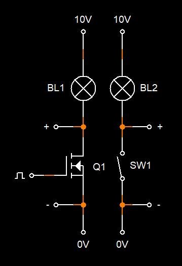
The PCB is a High Tech, Isolated, Flexible, Switch, so all normal Circuit Rules apply beyond this point. This Switch is Polarity Sensitive! Only Switching in one Direction!


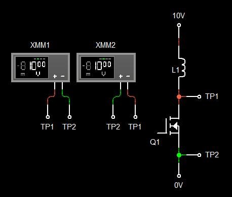
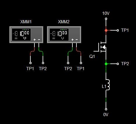
The two above Circuits are Identical in Principle! Q1 represents a single Channel of your PCB. Q1, we see, Polarity is Important, one way, its always on, because of the diode, the other way, its off, unless Q1 is turned on.

The big Mosfet here:


This is One Channel, a Complicated Isolated, Reliable, Flexible Switch, every single part must be Correct and placed properly also.

Beware of:

  • Too much Iron Heat, some parts may be sensitive to over heating!
  • Not enough Heat, Solder must flow and make good contact with the part, Soldering it to the PCB.


These PCB's are the absolute best thing you will ever invest in! They are worth their weight in Gold! Be thorough and meticulous, get these PCB's 100% and they will do almost anything you want them to do!

Don't forget, we have projects for Input PWM also:


Best Wishes,

   Chris

Forushani posted this 14 January 2021

Happy new year everyone. I am still here and trying to learn and proceed.


One suggestion, Chris.


Change the markings by PWM output from "+" and "-" to "In" and "Out"


I know as a beginner, that took me a while to figure out.


Thanks and god bless 

  • Liked by
  • Chris
  • Augenblick
Chris posted this 14 January 2021

Thanks Forushani,

There is only one Positive side and one Negative side in the Circuit no matter what way the Load is switched.

 You can see here, TP1 is always Positive:


Low Side Switching:


High Side Switching:


So there is always a Positive and a Negative. XMM2 shows the Polarity difference, and this means TP1 is always Positive.

Best Wishes,

   Chris

  • Liked by
  • ISLab
  • Augenblick
Forushani posted this 14 January 2021

Thanks Chris. What I meant was just label. You are the true MASTER


fer123 posted this 14 January 2021

Hello Forushani, I love this forum, Chris is the best, plus all the others working here, can you make a small video or something how to connect to a signal generator and power supply? I'am sort of beginning in electrónics I have try to used a audio amplifier, but I will like to built this switching module only I have a lot a faith in Chris an so happy he is from people side, today the evil(MONEY) change everybody. Thanks a lot.

We're Light Years Ahead!
Members Online:
What is a Scalar:

In physics, scalars are physical quantities that are unaffected by changes to a vector space basis. Scalars are often accompanied by units of measurement, as in "10 cm". Examples of scalar quantities are mass, distance, charge, volume, time, speed, and the magnitude of physical vectors in general.

You need to forget the Non-Sense that some spout with out knowing the actual Definition of the word Scalar! Some people talk absolute Bull Sh*t!

The pressure P in the formula P = pgh, pgh is a scalar that tells you the amount of this squashing force per unit area in a fluid.

A Scalar, having both direction and magnitude, can be anything! The Magnetic Field, a Charge moving, yet some Numb Nuts think it means Magic Science!

Message from God:

Hello my children. This is Yahweh, the one true Lord. You have found creation's secret. Now share it peacefully with the world.

Ref: Message from God written inside the Human Genome

God be in my head, and in my thinking.

God be in my eyes, and in my looking.

God be in my mouth, and in my speaking.

Oh, God be in my heart, and in my understanding.

Your Support:

More than anything else, your contributions to this forum are most important! We are trying to actively get all visitors involved, but we do only have a few main contributors, which are very much appreciated! If you would like to see more pages with more detailed experiments and answers, perhaps a contribution of another type maybe possible:

PayPal De-Platformed me!

They REFUSE to tell me why!

We now use Wise!

Donate
Use E-Mail: Chris at aboveunity.com

The content I am sharing is not only unique, but is changing the world as we know it! Please Support Us!

Thank You So Much!

Weeks High Earners:
The great Nikola Tesla:

Ere many generations pass, our machinery will be driven by a power obtainable at any point of the universe. This idea is not novel. Men have been led to it long ago by instinct or reason. It has been expressed in many ways, and in many places, in the history of old and new. We find it in the delightful myth of Antheus, who drives power from the earth; we find it among the subtle speculations of one of your splendid mathematicians, and in many hints and statements of thinkers of the present time. Throughout space there is energy. Is this energy static or kinetic? If static, our hopes are in vain; if kinetic - and this we know it is for certain - then it is a mere question of time when men will succeed in attaching their machinery to the very wheelwork of nature.

Experiments With Alternate Currents Of High Potential And High Frequency (February 1892).

Close