Zanzal's Easy BCFT Circuit

  • 2.6K Views
  • Last Post 14 March 2019
Zanzal posted this 05 February 2019

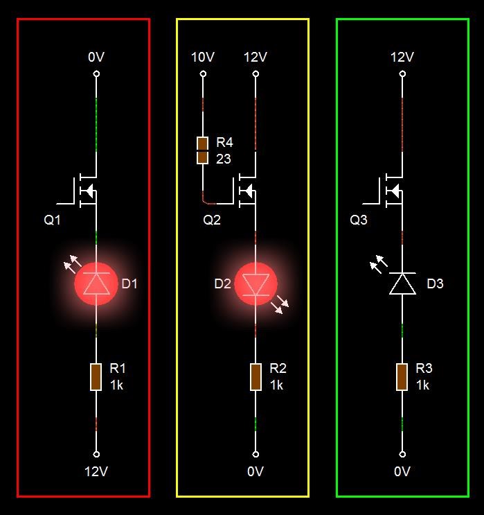
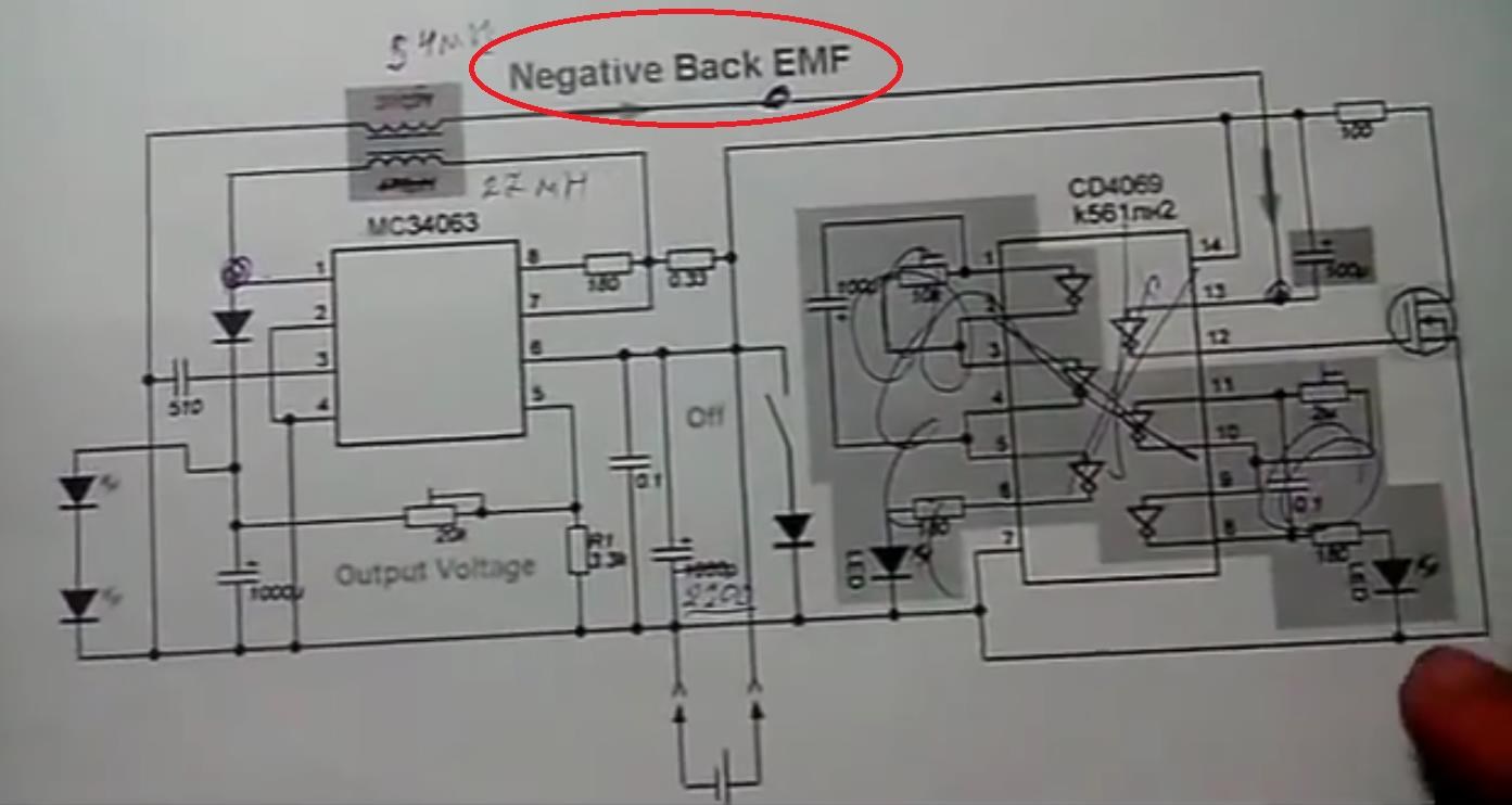
Note: This circuit appears to suffer from a problem where power is fed into the input pin leading to false conclusions about its performance.

I had some trouble getting YoElMiCrO's circuit to work for me as described. Initially I had thought I got it working, but it turns out I had made a mistake in my circuitry and ended up discovering a whole new oddity which may or may not get described in a future post.

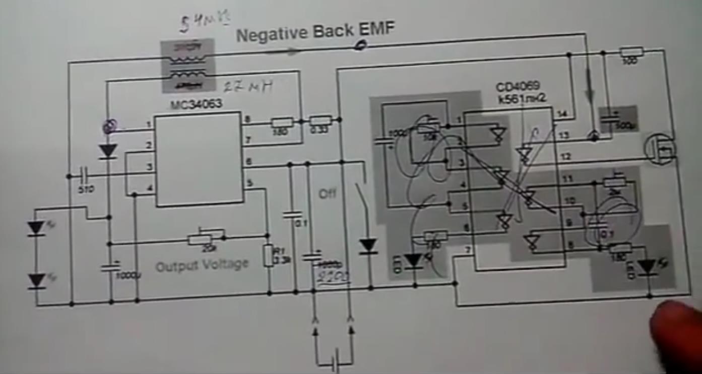
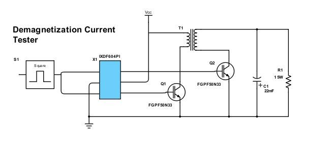
So why didn't YoElMiCrO's circuit work for me when it works for Chris and possibly others? I have no idea, maybe my core is too picky or my windings too shabby, or whatever. However, I was not discouraged. I devised some changes which I think make it easier to work with. I've named it the Easy BCFT (Bucking Coils in a Forward Topology). For me these changes took a 99% efficient magnetic resonance setup (which is easy to get) and kicked up a notch.

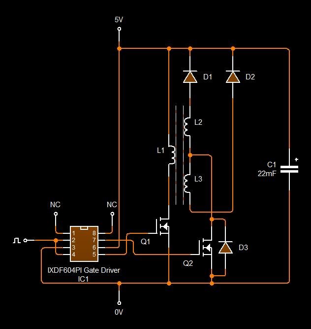
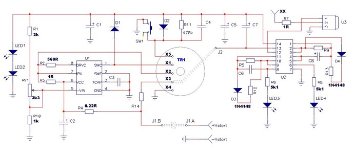
The circuit has two enhancements, first it uses an efficient IXDF604PI gate driver (or you can just use two separate efficient gate drivers one inverting and one non-inverting) or any other method that achieves the same outcome. The second enhancement is that the single mosfet has been replaced with two IGBTs that do not have anti-parallel diodes. This did fix some of the issues I was having and I was able to get a little bit power out of it (signs of life), but reverting back to the 1 to 3 ratio with more turns did work better than the original ratio at lower turns for me. 

Easy BCFT - 02/05/19:

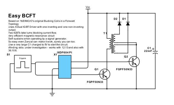
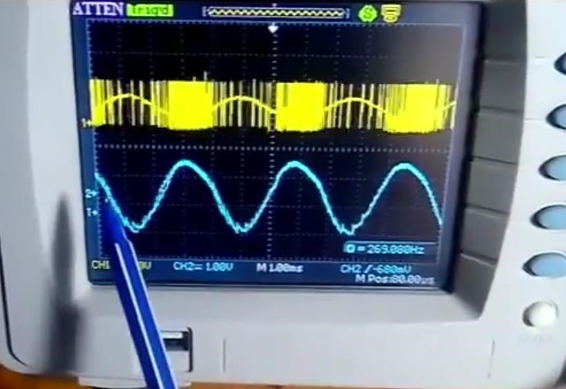
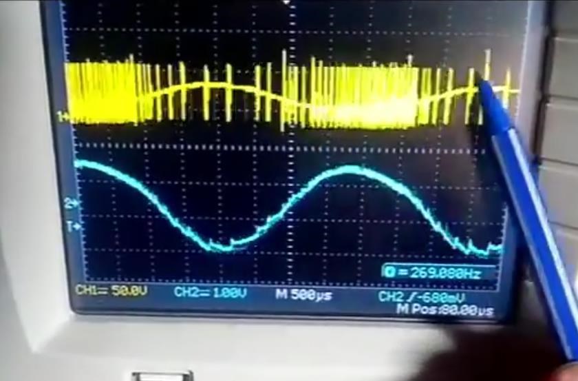
Duty cycle will likely be very low with on-times around 2-7uS and a wide range of frequencies that will result in successful operation. No special core gapping was needed.

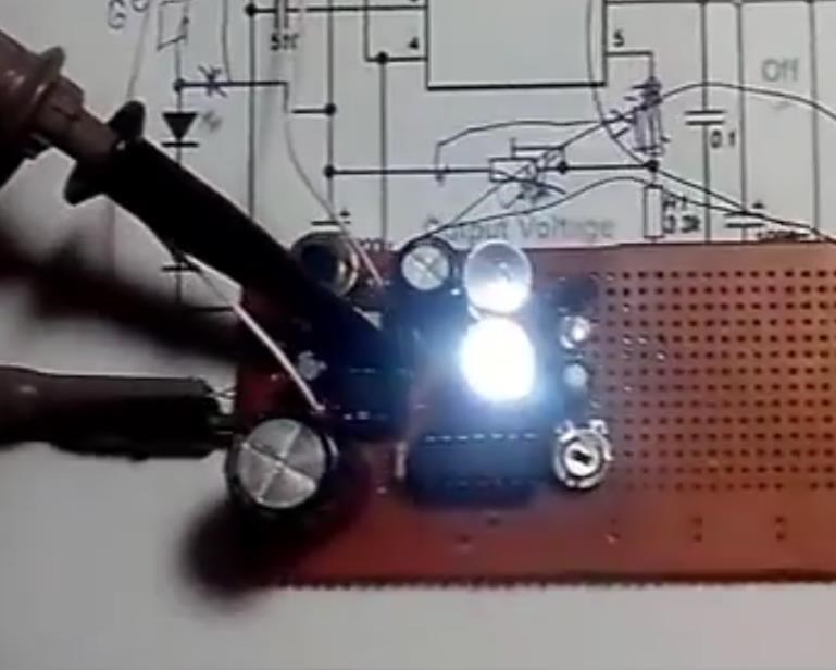
Powered only by the signal generator charging the tiny capacitors in the gate driver to 5V 65k times per second the circuit self-charges a 22mF capacitor to 8.1V (YMMV) and powers a small load of 3 series ultrabright LEDs. Sorry no specifics, yes its AU (Edited to clarify this was a false conclusion), no further numbers will be forthcoming, this is eternal lantern level stuff for those who are looking for kW. If you are successful in replicating feel free to share your opinion or results if you wish. Proven enhancements always welcome here, or better yet, create a thread to show off your improvements. Enjoy.

Order By: Standard | Newest | Votes
Chris posted this 05 February 2019

@Zanzal - I am so very proud of your results!

Well done my friend!

We are showing the world how it is done! Fantastic! And you have shown how easy this can be! Ones thinking has to be right.

   Chris


P.S: Apologies I did a small edit.

Zanzal posted this 05 February 2019

Well you should be proud Chris, it uses Magnetic Resonance and Asymmetric Reguaging, both of which you've been educating us on for some time. I think so far this is the most simple proof of concept for preventing conduction in the secondaries while the transformer is reguaging. Much thanks to YoElMiCrO for his very straightforward design.

If others results are as good as mine then no longer will lanterns need some finicky oscillator circuit, they could be powered by simple TLC555 using LEDs as a load regulator.

Zanzal posted this 05 February 2019

The tuning for this circuit is fairly easy, use a voltmeter on the capacitor to monitor the rise and fall of power on the capacitor. The capacitor should maintain a charge at some level if working and if it falls quickly then its not producing enough power and needs adjustment. If you have the ability to adjust the pulse width using time rather than % you may have quicker success. A decent "on time" will probably be proportional to the number of turns in the primary. The greater the turns the greater the on time. For mine this was 3uS at 12 turns and 7.5uS at 36 turns. Once a decent on time is found a wide range of frequencies should work at that on time.

One observation that may just be coincidental, is that I found that at the natural resonant frequency, the on time was roughly 50%. If you know how to quickly spot the natural resonance on an oscilloscope you may be able to quickly tune your device that way. Not sure if that was just my core or if that is something useful, more observations are needed.

Chris posted this 05 February 2019

@Zanzal,

Its all in the Timed Interactions of the Coils. Partnered Output Coils "Generate" Electrical Energy.

Well done my friend wink

You have that huge Wall of Water:


Ref: https://www.youtube.com /watch?v=EUXOZAinUPk


The Force is greater than the Initial Force. Conduction is hugely important, more so than we currently think.

   Chris

  • Liked by
  • Zanzal
  • Wistiti
Wistiti posted this 05 February 2019

Excellent work!!

  • Liked by
  • Zanzal
  • Chris
Vidura posted this 05 February 2019

Hey Zanzal, I'm happy about your success! And certainly I like the simplicity of your circuit, the employed principles are clear and easy to understand.and also credits should be given to Yoelmicro for sharing the basic idea.Great work!

  • Liked by
  • Zanzal
  • Chris
Chris posted this 05 February 2019

Hey Zanzal,

When you have a minute, if you would like to add to, or point out any additions to my post here: How to build your own Above Unity Machine - Perhaps just a few bullet points if you have any?

I would like to encourage all to build and replicate this work, and also, remember, the basic outline, many ways work, this is just one excellent example! Do not limit yourself to any specific configuration!

I always encourage simplicity! 

Keep it cheap and simple, $20 and an hours work when one knows what is required.

Its how you think about it, when you have learnt enough, the rest is extremely simple! All of Andrey Melnichenko's early Circuits were doing the same thing! All of Akula's early Lantern Circuits were doing the same thing! All of Don Smiths Circuits were doing the same thing, All of may others Machines are doing the same thing.

We are following in the footsteps of the greats, before us. We should thank them for the contributions they gave! However, it is you making a Global change! Be proud, you are Part of something Better!

   Chris

Chris posted this 05 February 2019

My Friends,

I want to point out, we have seen this before, here: "Partnered Output Coils - Free Energy", and also here, but the Circuit Zanzal has shared does have two Current Directions and these directions are perhaps not realised by some.


D3, the internal Mosfett, or internal IGBT, Diode, most have, but some don't, so, we must consider the switch Q2, ON in one direction all the time. I posted some info about this before, mentioned above:


So, I urge, don't forget about the Conduction Paths, Arrows are running in two different directions, this was pointed out by YoElMiCrO also.

   Chris

YoElMiCrO posted this 05 February 2019

Perfect zanzal.
I'm glad it works.
If the time of Ton is linked to the number of turns.
The relation is Ton = NpBmAe / Vp.
The load should be in constant tension, as the fordward voltage of a led, which is kept constant for a certain variation of current.

It is important to note that it is only possible to extract energy during the fordward cycle, also remember that Q = CV = it.
I already have the 3W Led in my hands, but it's late, tomorrow I'll try to test the circuit I designed with the controller.

Thank you.

Zanzal posted this 06 February 2019

Hey friends,

I think there may be a problem with this circuit. The signal generator appears to be feeding power in through the input pin. This was not expected, and is disappointing. Feels like another huge fail on my part.

Just thought I should give you all a heads up. Looks like I am going to have to eliminate the signal generator from all future tests. Confirmation bias strikes again. I'll keep working on it....

Chris posted this 06 February 2019

@All,

Yes, this is a consideration! Leakage is mostly extremely small, in the nanoamps and normally indicated on the datasheet somewhere:


This is a matter I also experienced some years back replicating a Cap Coil setup that seemed to be running by itself at the resonance frequency, not powering any load.

I must urge, don't be discouraged, this small problem is not enough to light 3 LED's and run the System all at the same time. So a small issue like this most definitely is not where all Above Unity Machines get their excess power from, obviously!

   Chris


P.S: Zanzal's variant of YoElMiCrO's circuit has huge potential. After all, YoElMiCrO's circuit has the exact same principles as Akula's Lantern circuit!


  • Liked by
  • Vidura
  • Zanzal
Vidura posted this 06 February 2019

Hey Zanzal,

considering the issue with the signal generator in my opinion there is no leakage to be considered regarding the IGBTs (or MOSFETs) as the driver is powered by the circuit rail in your schematic. If there is  leakage it could be only thru the driver IC, and only if the voltage of the SG output is exceeding the railvoltage. you could try to lower the output voltage of the SG or use the TTL output.

I hope this helps some.

Vidura

  • Liked by
  • Zanzal
  • Chris
Zanzal posted this 06 February 2019

Vidura/Chris, I agree, the circuit is still promising and leakage current through the gate is an insignificant consideration for what we do. Which is why I did not question the results.

I verified my concerns using a tester that there is a diode in the gate driver between in and Vcc. Voltage drop was 773mV. Also, part of what I noticed last night that made me realize there was an issue was that I noticed my input voltage was set to 10V on my signal generator, I had recalled setting it to 5V, but I must have changed it at some point. Setting it back to 5V caused a dramatic loss of power.

Inspite of this mistake the circuit itself has potential because the switching and the efficiency of the gate driver is good. I just have to make sure that future tests use self-contained switching. As long as the signal voltage never exceeds Vcc then a signal generator can be used, but I don't like repeating the same mistakes over and over again, so my next priority is an ultra low power square wave generator.

  • Liked by
  • Chris
alohalaoha posted this 06 February 2019

Hey Zanzal

Your choice of current driver IXDF604PI is good. As you already know you can put in parallel as many as you wish same type drivers. On that way you will boost current source/sink capabilities over the single driver and also drastically drastically lower input time constant of MOSFET/IGBT transistor or simply, shorten gate/source(emitter) parasitic capacitor charge/discharge cycle.

I like your IGBT option because he has not parasitic intrinsic body diode between drain/source(emitter).

Also any good newest generation Silicon Carbide Power Mosfets could be used here, simply adding pair of antiparallel very fast recovery high voltage high current diodes to transistor's output to cut-off intrinsic diode.

ps: Maybe is time to put some isolation transformer between your function generator and test circuit. You can make one easy with small toroid ferrite ring and pair of primary/secondary winding in 1:1 ratio. Diametr of wire 0.3-0.5 mm.Number of windings 30-50 each coil. Also is useful to make small air-gap 0.5mm or smaller in the ferrite ring to avoid core saturation. Wind two coils in the same time (in parallel) and mark start and end of windings. This type of isolation transformer is preferable for HV test setups.


Reg.

Aloha

Jagau posted this 07 February 2019

Hello Zanzal


Yes I believe like you that your circuit has a lot of potential and for that,

if you want I can suggest you a very simple circuit which works even with a very low output TTl

and which protects us from the short circuit which could damage the DUT

This circuit I use it with almost all the experiments that I do, it uses an optocoupler and a mosfet.

Resistor R2 provides current limiting to prevent Q1’s gate-source capacitance

damaging the driver’s output at turn-on.

It may also be necessary to prevent the MOSFET from oscillating.

A value of a few hundred ohms is usually suitable.

This little circuit I avoided many bad surprises as you have recently lived

Jagau


Chris posted this 07 February 2019

Hey Jagau,

Agreed. Many ways exist to isolate this problem. Your method is a good example. Thanks for sharing!


On another note - What causes Transients?


Say one was given the task of creating a Transient, it had to be a particular Voltage Amplitude. How would one go about this?

Its easy right? Zanzal's Circuit will Cause a Transient! But the Circuit must be right, one Coil must conduct, the Switch must then Bang, hit the Magnetic Field hard, this very fast change in Magnetic Fields will cause a large Transient. Why do we want to look at this? Because: I = V / R

Current increases with Voltage, and the Resistance, or Impedance, can only drop. Reduced Impedance Effect.

Don't give up! This circuit has a lot of potential, its been used before! Graham Gunderson's Circuit is very similar! I urge all here, this circuit will work, but again, follow my basic outline in my thread: How to build your own Above Unity Machine

   Chris


  • Liked by
  • Jagau
Jagau posted this 07 February 2019

Hi all

As I already said in one of my threads
the effect is greater when the primary coils are asymmetric with different inductances (lengths of coils)

Don Smith has already explained that this creates a slight delay on one side of all the coils

and he was right, I got better effects that way


Jagau

  • Liked by
  • Chris
Chris posted this 10 February 2019

@All - I urge all go back and revisit the facts.

This method does work! The Coils slap together as hard as the can, Magnetic Fields Oppose, Currents Oppose! When this happens, the Voltage in the Terminals Increases, because of the very fast Time Rate of Change of the Magnetic Fields.

Work up around the Knee of the Saturation Curve, this can be seen on the Scope as the Peaking on the Current Waveform:


Seen in Red, the Current will start peaking, so at this stage turn down the Voltage just a little until the wave goes back to Sinusoidal.

High Frequency I have had not much luck, most all of my machines are low frequency and more turns. As an example of this:


Akula also used low Frequency on most of his smaller units: 260 Hz, remember this is Andrey Melnichenko's machine, not Akula's. He only replicated the machine.

If you look at the Wave form, the direction of the Diodes and the discharging mosfet, triggered by the Voltage on the Cap/Coil via the CD4069 Hex Inverter, it is indicated the Current is in reverse.

DONT give Up! Remember: Equal and Opposite! You guys are practically there! You have all the pieces of the puzzle! Look at all the spikes, Look at the Duty Cycle Pulses, look where they are and what they are doing... The Waves Slap together and a Wall of Force Grows, like this:

Ref: https://www.youtube.com /watch?v=EUXOZAinUPk


This is the Regauging Part, then the Wall has to dissipate!


The resulting force is much Larger than the original Wave, it can be more than twice as high as is predicted in Science!

Ref: https://www.youtube.com /watch?v=MFmQhx5Wq3E


Quite some time ago I posted this to try and help:


This we have already seen! Electromagnetic Waves are exactly the same, we can manipulate them exactly the same way!

   Chris

Zanzal posted this 10 February 2019

I didn't have much luck with AU yet, but I decided to take a different approach. Using this circuit to study what happens when the core demagnetizes.

The method is simple, using my original circuit with only two coils and a 1ohm resistor between the secondary and Q2, I make a floating measurement over the 1 ohm resistor using a handheld oscilloscope. By swapping coils I can study how the current flow changes.

The results are.. peculiar, somewhat unexpected, and even inexplicable at times. As an example, the current configuration under test at 300Hz and 4.7% duty cycle would have me believe that the peak discharge current exceeds 2amp and flows in the wrong direction inspite of the diode D1 which should prevent such a thing. I'm not really sure what to make of it.

  • Liked by
  • Vidura
  • Chris
Zanzal posted this 11 February 2019

For those who wish to try this experiment, the results may depend significantly on the windings and whether anti-parallel diodes are present. IGBTs without anti-parallel diodes are important for this experiment. My best results so far were with a primary of 36 turns and a secondary of 12 turns. The demagnetization occurs over a fairly short period in my case about 12uS. Spacing between the coils and power drawn by the primary are important.

If there is a relationship between this and bucking coils AU, then presumably cores and windings might be evaluated based on maximizing the efficiency and size of the demagnetization "current." Or at least that is the theory I am currently pursuing. Given that primaries of 12 and 108 turns did not work good for me it may be there is a sweet spot.

The lack of predictability in the results of each test discourage me from making too many generalizations about this right now, so the above is provided solely as means of helping those interesting in performing similar research.

I really don't like that the apparent current seen through the resistor is reversed or negative, but I can't find any mistake in my probe settings. Probes are not inverted.

Anyway, if anyone can reproduce it I'd love to hear some opinions.

  • Liked by
  • Chris
Chris posted this 11 February 2019

Thanks for sharing Zanzal!

Of course we have seen these effects in The Mr Preva Experiment and also in my Thread: Some Coils Buck and some Coils DONT

Effects that are very important! Effects that MUST be understood!

We have had this in our Faces for quite some time and the obviousness of this is not realised for sake of tripping over it. Pointed out by Akula:


So, now, Turns and Timing is where you need to focus, you have the effects, now all you need do is Increase this very simple effect! The Magnetic Field in the Core is limited to Saturation, and if you are close, but not at saturation, the Maximum Magnetic Field can be used. The Time Rate of Change of the Magnetic Field is where you can make this work.

An Input Coil with few turns and very low resistance, a short sharp DC Pulse brings the Core up close to saturation, the knee of the curve. Then the Partnered Output Coils can work for Longer, the Time the Coils have to Interact together, because the Magnetic Fields Time Rate of Change is slower, a Linear Decrease over time. But the initial Potential must be bought up! Voltage, once you have enough Terminal Voltage, the Gains will very easily exceed the Input!

   Chris

  • Liked by
  • Jagau
  • Zanzal
Jagau posted this 11 February 2019

You're right Chris


We must focus and work together.
I think we are close to the goal,

if we take for example the eternal lamp of Akula I focus these days to reload the primary capacitor C1 to restart the system continuously. The proposed scheme gives an idea but it does not work this way.

The lamp I had at first works for more than an hour but the oscillator stops working well before. The C1 capacitor must reload continuously, this is the aim of this project with the BEMF is the key to success

I am testing a concept that John Bedini had and it seems to work better, to follow.


Jagau

  • Liked by
  • Zanzal
  • Chris
Chris posted this 11 February 2019

Exactly...

We must focus and work together.

My Friend, I completely agree.

You know, it was said by Sir Richard Feynman:

So you see, that the real Energy change is the Negative of the Mechanical Work, and that's why I keep writing this as EArtificial, because the true Energy of the world, is the Negative of EArtificial, in this case is μ.B - I just want to point out that difference in Sign, but that's just interesting.


It was noticed by this great man! We have two different types of Energy! The negative of what we use: EArtificial the opposite of Universal Energy! Real Energy. Thus my Profile Image, subliminal response to EArtificial.

   Chris

  • Liked by
  • Jagau
  • Aetherholic
Zanzal posted this 12 February 2019

More to come on this, making tons of great progress. I think I am beginning to see where the problem with this circuit is. I don't have a redesign yet, but I definately can see where a bit of ignorance on my part has led to a fatal flaw. Perhaps it would have worked better with a different IGBT, but not with the ones I am using.

Here is the demagnetization test circuit that I'm having good success with.

Lots of great results, easy to use. It does rely on the fact that the IGBT doesn't seem to want to conduct in reverse (the ones I am using). I don't have a lot of experience with IGBTs but those with a body diode definately will not work for this circuit.

This circuit is easy to get good data from. Using a 1ohm resistor the capacitor charge level will tell you how much output power is in the demagnetization current. For an idea of what kind of power one might expect from a demagnetization current, I was able to get it up to 1.1A continuous over the 1ohm resistor (1.2W out for 2.6W in). Now while that might seem like bad efficiency, It is actually quite good, and it is very promising.

Initial tests had an efficiency of < 10%, and I was able to bring it up significantly, and I see signs that this can go much much higher. Interestingly I found that tapping the flyback on Q1 is still possible though I do not offer a practical circuit at this time to demonstrate this as I think the real value will be in realizing the original goal of asymmetric reguaging in a configuration that doesn't impede current flow (which is the flaw in the original circuit).

Chris posted this 12 February 2019

Thanks for sharing Zanzal,

I think a DC to DC Converter is what you have in this Circuit, and by the description it sounds the same. The MC34063 is a DC to DC Converter IC, used in the above circuit layouts I shared.

While this is a part of the End Goal, it is not enough to get you Above Unity Efficiency.

A second Coil must be used, Increasing the Rate of Kinetic Energy, otherwise we are simply not "Generating" any excess Electrical Energy. In the Wire:


Where, Charge ( Cyan Ball ) directly associated with the Copper Atom Cu, is Charge under Acceleration.


As long as we have a Symmetrical Energy Transformation, no gain is seen. We must have an Asymmetrical Regauging System! We must realise, in a Transformer, Energy is Transformed in a Symmetrical way, from Input to Output.

With some fiddling, close observations, your first circuit will give you better results. Timing and Turns is all you need adjust.

   Chris

Zanzal posted this 13 February 2019

As long as we have a Symmetrical Energy Transformation, no gain is seen. We must have an Asymmetrical Regauging System! We must realise, in a Transformer, Energy is Transformed in a Symmetrical way, from Input to Output.

With some fiddling, close observations, your first circuit will give you better results. Timing and Turns is all you need adjust.

If one expands the demagnetization test circuit to accommodate a third winding the workings of such a change will be evident in the results. To fully appreciate the results one should consider first studying a two winding version first.

Zanzal posted this 15 February 2019

Some random thoughts:

  • We know when a current is flowing through an inductor that its "inertia" or resistance to change goes both ways. That current takes time to build and once built it will take time to slow down.
  • When you take a charged capacitor and you discharge it rapidly through low resistance it will ring. In the simulator it shows the voltage can go very negative. If you short the capacitor through a diode it can overshoot and the capacitor will experience a reverse polarity almost as great as the initial polarity.
  • We take a toroidal inductor and run a little DC through it, then we stop charging the inductor and allow the field to collapse, the above demagnetization circuit appears to prove that this action generates a current in the secondary.

Now lets say all the above are true and I believe they are though I've not personally tested capacitive reversal outside the simulator or overshoot as its sometimes referred too I have no reason to believe polarity reversal not real. We might wonder then if the demagnetization circuit can induce a magnetic field overshoot. That is the magnetic field collapse may drive the current up but once the field is collapsed the current will still want to flow and if that flow is large enough it may drive the field into reversal before it stops. If then that reversed field were then discharged it might drive the magnetic field back into the other direction. If timed correctly a resonance could be achieved.

If a magnetic field overshoot could be achieved it might only manifest if a sufficient load were present. No load = no current = no overshoot.

Just an idea I thought I'd float.

FWIW, there is a positive correlation between demagnetization current efficiency and the input power.

Jagau posted this 15 February 2019

Hi Zanzal

a third winding the workings of such a change will be evident in the results

I always get better result with a third winding  i it is a very goog choice.

Jagau

Chris posted this 15 February 2019

Hey Zanzal,

If you don't mind me saying: "I believe you need to think more broadly about the Currents and the production of such Currents."

When you say:

demagnetization current


We are not using / depleting the de-magnetising current as such.


What we are doing is using the Change in Currents, to produce more currents.


Lets look at an example. Water Current and Electrical Current are analogous to each other. This we already know, but for other readers, we need to be clear. We will use some imagination. In the following image:


We see Current of the River moving from left to right. However, we also see eddy currents created that turn and move the opposite direction, from left to right. I am sure we have seen this before and everyone knows how this works.

Imagine, we can add and remove the small point, marked in grey, we can add and remove this at will. Like so:


So you get the idea.

Our Coils do the same thing! We add and remove Conductivity with a timing to produce extra, otherwise not there, Currents. Nature shows us, they must always flow in the opposite direction, unless we have a function forcing the current to do otherwise, as in my thread: Parallel Wire or Bifilar Coil Experiment - the bifilar wound transformer, the Input forces the Current to flow in one direction at all times in the Secondary Coils.

So, we add and remove the Conductivity in the Coils at a specific time, individually, creating large Voltage Potentials on the Terminals, because the faster we add and remove the obstruction, the faster the currents are forced to change, and the Standing wave creates a potential that must decrease linearly over time if Conduction is held steady.

This is exactly the same as dropping the Neo Magnet through the Copper Tube:


We must also realise, as you have pointed out, there is actually more than one, more than two, but actually four currents, each wire has the effects of Lenz's Law, each change is a reoccurrence of the neighbours change in Currents. So we have for each Coil, waves and anti waves. This was pointed out by Tom Bearden and I have seen what he means in experiment.

There is however, a situation where one can offset the waves, and end up with five waves. The fifth wave, the demagnetising Current that you have pointed out is not affected by the four other waves.

A long winded explanation, sorry. 

   Chris

  • Liked by
  • Zanzal
  • Vidura
Zanzal posted this 15 February 2019

@Jagau, yes I found it the same, an extra winding always seemed to make it better, but for now I am only using two. In my case I did not experience a doubling with two secondary windings. I suspect that it lowers the effective resistance of the discharge path. Like two resistors in parallel have half the effective resistance, perhaps it is similar.

If it interests you, you may also find that applying a strong magnetic bias can increase the efficiency a little. To me this seemed polarity and core material dependent. I think it was more effective with the amorphous toroid cores and with some cores (sendust) it was very bad. This may be related to do with what cd_sharp was experimenting with. I don't think adding permanent magnets is a good path forward (I could be wrong), but I find it interesting that it does seem to fit with some theories of William Alek.

My best efficiency with a two winding pot core 40 turn primary 12 turn secondary was 68% though that was a short run as my 5W resistor started smoking. I think I will need to upgrade to a 100W resistor, get rid of the breadboard, and add some large heatsinks to push the efficiency any higher.

Zanzal posted this 15 February 2019

Yes Chris, I think about this stuff a lot. For example the other day I was thinking about how if you take a large toroid and wrap a single winding around it covering the toroid then all the magnetic vectors produced by the windings sum in the same direction inside the toroid core itself and also outside the toroid. But not inside. Inside they sum in the opposite direction. Or so it would seem (thought experiment only). I have pondered what would happen if you put a small toroid in the center of the large toroid and wondered how a winding around that toroid would respond to changes of current in the large toroid. Perhaps some day I will have time to test it but for now I have to finish these experiments before I can move on to other things.

EDIT: Actually now that I think about it again I think they always sum in the opposite direction when outside the core. Whether its on the inner or the outer perimeter should not matter. Still very interesting to consider what effect that might have if anything.

  • Liked by
  • Chris
  • Vidura
Atti posted this 16 February 2019

 I have pondered what would happen if you put a small toroid in the center of the large toroid and wondered how a winding around that toroid would respond to changes of current in the large toroid. 

Hey Zanzal. I've been doing a similar experiment in the days.

  • Liked by
  • Chris
  • Zanzal
Atti posted this 16 February 2019

Hey Zanzal and everyone.

What I am mentioning to others now is perhaps clear. That may not be a good idea. But you'll fix it if you need to.
My whole initial investigation began with a cloak type (E I) transformer. I was wondering how the primary and secondary coils affect each other. When the power line comes out, where and when saturation. This is seen in the first half of the video. Here's an old MOT transformer with two identical rolls. The secondary is a 40y capacitor. It can be seen how at the right resonance the relationship of the two coil phases develops. At that time, berezona and the magnetic flux will exit the iron. Closes inside between primary and secondary coils. The iron plate near her is the best one here. So I had to measure just how much this value was for signaling. I took out a little ferrite cylinder, a few threads at the end of the thread with a 22 ohm resistance and a multimeter. I wanted to see the scattered flux route. The idle characteristic is that the flux closes only within the iron core. Therefore, both rolls are closed with the same flux. In the state of load or short circuit, the threads of the coils are connected by different fluxes.
That's why roll flux and iron flux. The flux image is also different if, for example, an external or internal winding is excited by a chain-type transformer. Alternatively, the secondary is short-circuited.
(The operating state of the load is between the idle state and the short-circuit condition.)

One picture about this: 

a, external coil excitation
b, internal winding excitation
 
a, in the case of the column of the iron core, the flux may fall to 3 ... 5% of its idle value.

b, in the case of flux, may increase to 103 ... 115% of the idle value !!!

So the other thing is what we do with it or what are the options. Because the higher flux rate change results in more tension!

A video of a toroid in the video from 0:50.
In the video, a 2: 30 core type transformer is tested in two ways. Measured blank and then measured in tight or loose coupling.
At first, close coupling involves excitation and load.
Here, the measured measurable value decreases.
(values ​​are for information only)
In the second case, the value of the loose coupled secondary coil is increased. Larger flux exited.
Thus, the secondary flux has a greater influence. I am thinking of, for example, the MEG device. Or I deal with the device of Árpád Bóday. I've already written about this. It was only in such cases that he was willing to work the permanent magnet properly.In addition, the position of the permanent magnet should be between the two coils.

From my device image: 

I'm sorry if it's long and incomprehensible.

Zanzal posted this 16 February 2019

Hey Zanzal. I've been doing a similar experiment in the days.

I'd be very curious to hear your results.

  • Liked by
  • Chris
Atti posted this 17 February 2019

Hello Zanzal. Unfortunately, there is no good result.
The internal toroid only has measurable voltage if:
- the outer toroid is in an over-excited state
- if the secondary toroidal is in a near-short-circuit condition
In this case, the power line exits and enters the inner toroid. But not significant.

Zanzal posted this 17 February 2019

Hello Zanzal. Unfortunately, there is no good result.
The internal toroid only has measurable voltage if:
- the outer toroid is in an over-excited state
- if the secondary toroidal is in a near-short-circuit condition

A negative result is a good result too in some cases. I didn't own the toroids needed to test the idea and now I know I don't need too. Thank you for taking the time to share your result. I appreciate it.

  • Liked by
  • Chris
  • Aetherholic
Forelle posted this 13 March 2019

Hi all, I would like to give a short Update from my progress.I built Zanzalβ€˜s easy BCFT circuit,it works very good but i still dont have reached magnetic Resonance,you hear from me when i get it. Thank you for this Forum.πŸ‘πŸ€πŸ™

Zanzal posted this 13 March 2019

Hi all, I would like to give a short Update from my progress.I built Zanzal‘s easy BCFT circuit,it works very good but i still dont have reached magnetic Resonance,you hear from me when i get it. Thank you for this Forum.πŸ‘πŸ€πŸ™

Excellent, I am glad you found the circuit helpful. I learned a lot from it and variations of it. I came away with the impression that the circuit is hindered by losses and the forward topology makes it hard to avoid some of them. If you have improvements to share please feel free too.

If you have trouble, it may make sense to modify the circuit to run the primary RLC resonant and to experiment with variations that do not self-feed. Care may need to be taken to avoid damaging the IC if rlc resonance is used, but I think it is essential to maximize efficiency. You may also find that the diodes introduce losses. I found that I could reduce the effective Vf using diodes in parallel. I believe this is because there is a small series resistance component that makes up the Vf and that portion of the Vf can be mitigated but there are diminishing returns as the leakage current and capacitance of the diodes will also add in parallel. 

Forelle posted this 14 March 2019

Hi Everyone So far it works best for me with a Fullbridge rectifier or without diodes,with only 2 diodes i have the badest Performance,i guess it has to do because i have Not the 180 degree phaseshift of the current and Not tuned to resonance.I am at the beginning and have to spend more time.The good thing is that from now on i know for what i am looking. Have a good day. Oliver

We're Light Years Ahead!
Members Online:

No one online at the moment


What is a Scalar:

In physics, scalars are physical quantities that are unaffected by changes to a vector space basis. Scalars are often accompanied by units of measurement, as in "10 cm". Examples of scalar quantities are mass, distance, charge, volume, time, speed, and the magnitude of physical vectors in general.

You need to forget the Non-Sense that some spout with out knowing the actual Definition of the word Scalar! Some people talk absolute Bull Sh*t!

The pressure P in the formula P = pgh, pgh is a scalar that tells you the amount of this squashing force per unit area in a fluid.

A Scalar, having both direction and magnitude, can be anything! The Magnetic Field, a Charge moving, yet some Numb Nuts think it means Magic Science!

Message from God:

Hello my children. This is Yahweh, the one true Lord. You have found creation's secret. Now share it peacefully with the world.

Ref: Message from God written inside the Human Genome

God be in my head, and in my thinking.

God be in my eyes, and in my looking.

God be in my mouth, and in my speaking.

Oh, God be in my heart, and in my understanding.

Your Support:

More than anything else, your contributions to this forum are most important! We are trying to actively get all visitors involved, but we do only have a few main contributors, which are very much appreciated! If you would like to see more pages with more detailed experiments and answers, perhaps a contribution of another type maybe possible:

PayPal De-Platformed me!

They REFUSE to tell me why!

We now use Wise!

Donate
Use E-Mail: Chris at aboveunity.com

The content I am sharing is not only unique, but is changing the world as we know it! Please Support Us!

Thank You So Much!

Weeks High Earners:
The great Nikola Tesla:

Ere many generations pass, our machinery will be driven by a power obtainable at any point of the universe. This idea is not novel. Men have been led to it long ago by instinct or reason. It has been expressed in many ways, and in many places, in the history of old and new. We find it in the delightful myth of Antheus, who drives power from the earth; we find it among the subtle speculations of one of your splendid mathematicians, and in many hints and statements of thinkers of the present time. Throughout space there is energy. Is this energy static or kinetic? If static, our hopes are in vain; if kinetic - and this we know it is for certain - then it is a mere question of time when men will succeed in attaching their machinery to the very wheelwork of nature.

Experiments With Alternate Currents Of High Potential And High Frequency (February 1892).

Close