My Friends,
This Thread needs more Focus, but the Melnichenko threads also need attention...
The Magnetic Field of POCOne is the place to focus because, we have a Source of Energy that is normally ignored, lost, and thrown away.
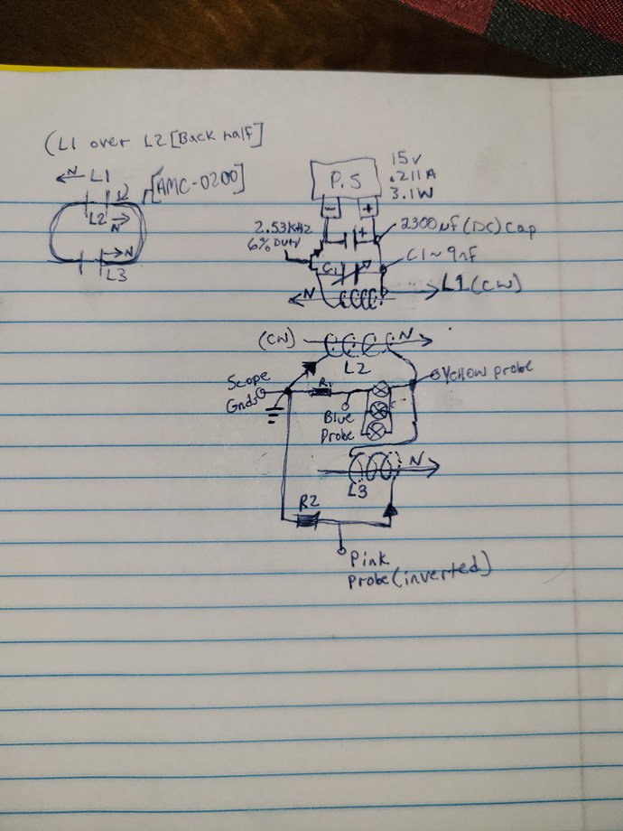
In Faradays Law Equation:
E.M.F = -N dΦb / dt
POCOne provides the: dΦb part of the Equation for POCTwo, which is the Voltage "Generated" in POCTwo! If dΦb of POCOne was 0.5 Gauss to 5000 Gauss, this is the Delta from BMax to BMin, then this is a very good Source of Energy! Right?
POCOne dΦb = 5000 Gauss - 0.5 Gauss = 4,999.5 Gauss.
POCTwo, has turns N, and this again is seen in the Equation. Of course the Sine Opposite ( - Negative Sign ) gives us the Bucking Field we need!
POCTwo, has a Magnetic Field that is In Phase with the Input Coil, it Assists the Input Coil, and as a Result, the Input Coils Impedance increases and the Input Current Drops as a Result of the Impedance Z going Up!
The End result is: POCTwo assists the Input Coil, but Opposes POCOne. Think about it, if: POCOne Opposes POCTwo, then one of the Coils MUST Assist the Input Coil! Right?
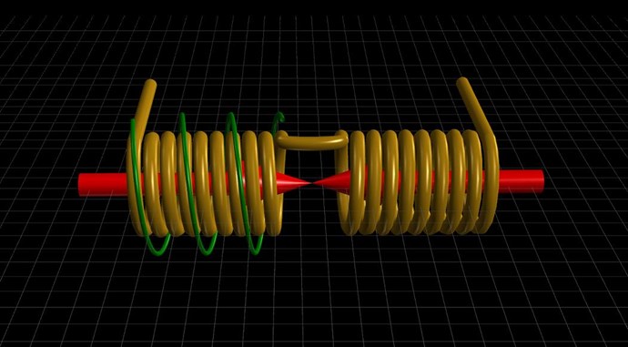
This is Asymmetrical Electromagnetic Induction! An area Science has entirely Neglected and Ignored! A new and proven area of Science that AboveUnity.com has introduced to the World!
Best Wishes,
Chris


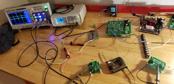
.jpg?width=690&upscale=false)
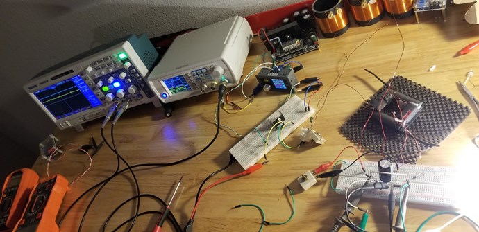


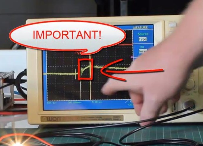


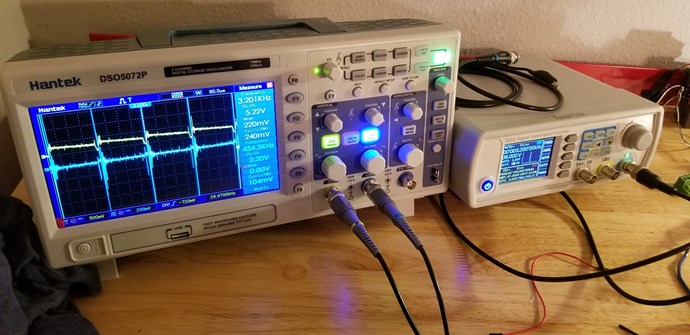
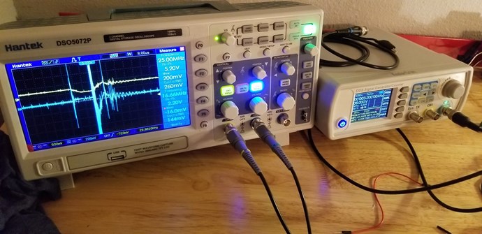
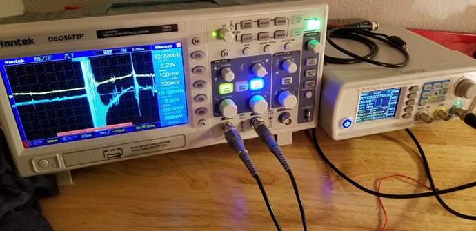
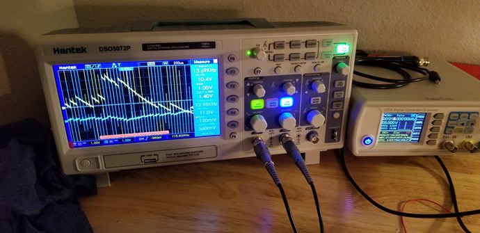
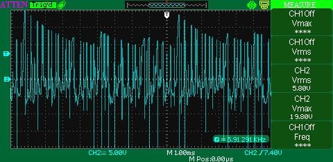
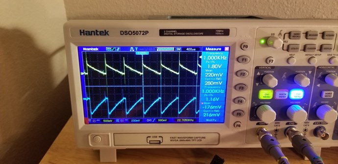
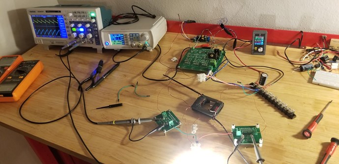
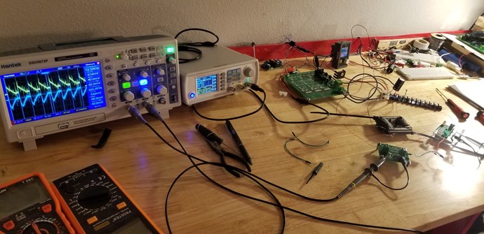
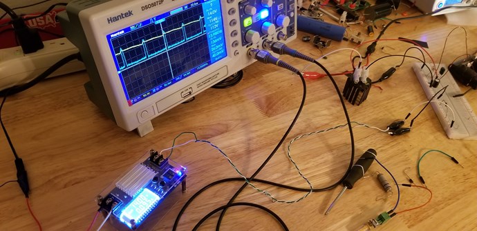
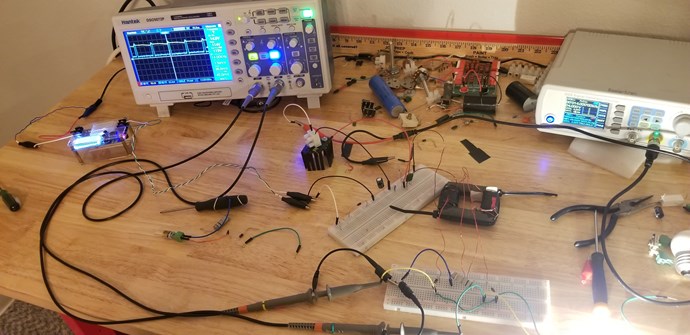
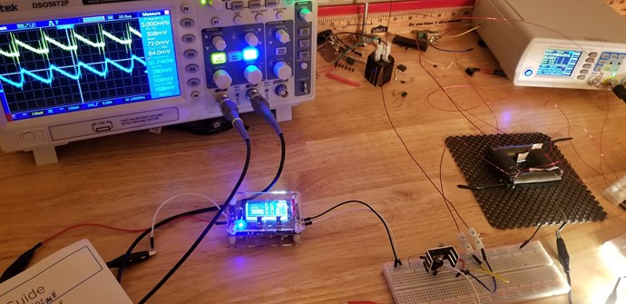
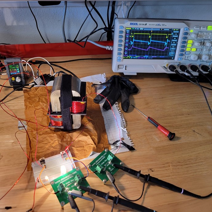
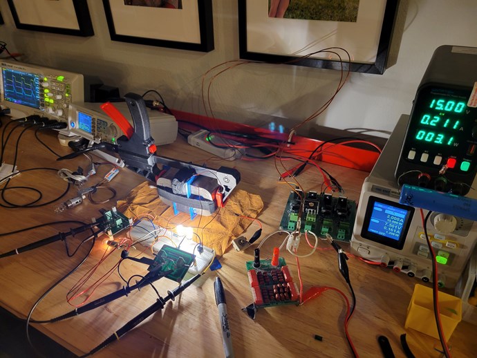
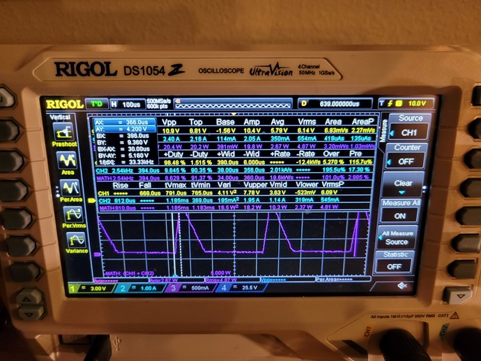
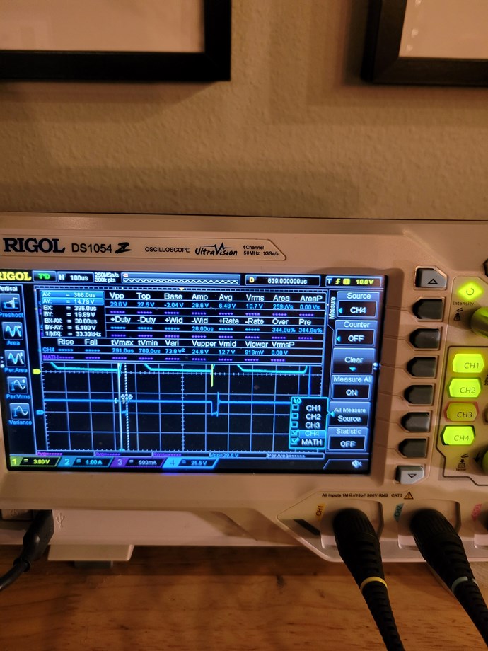
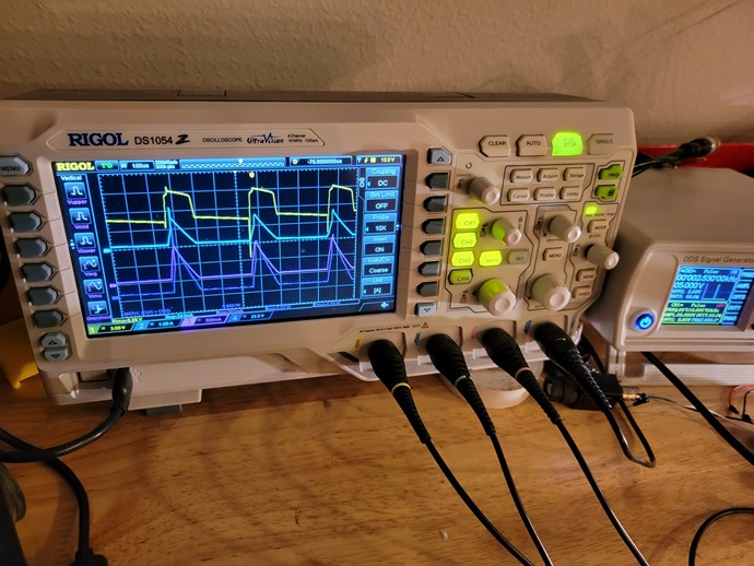
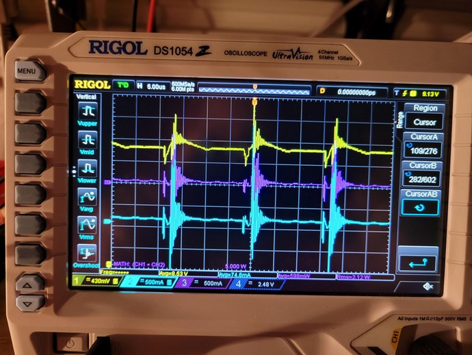
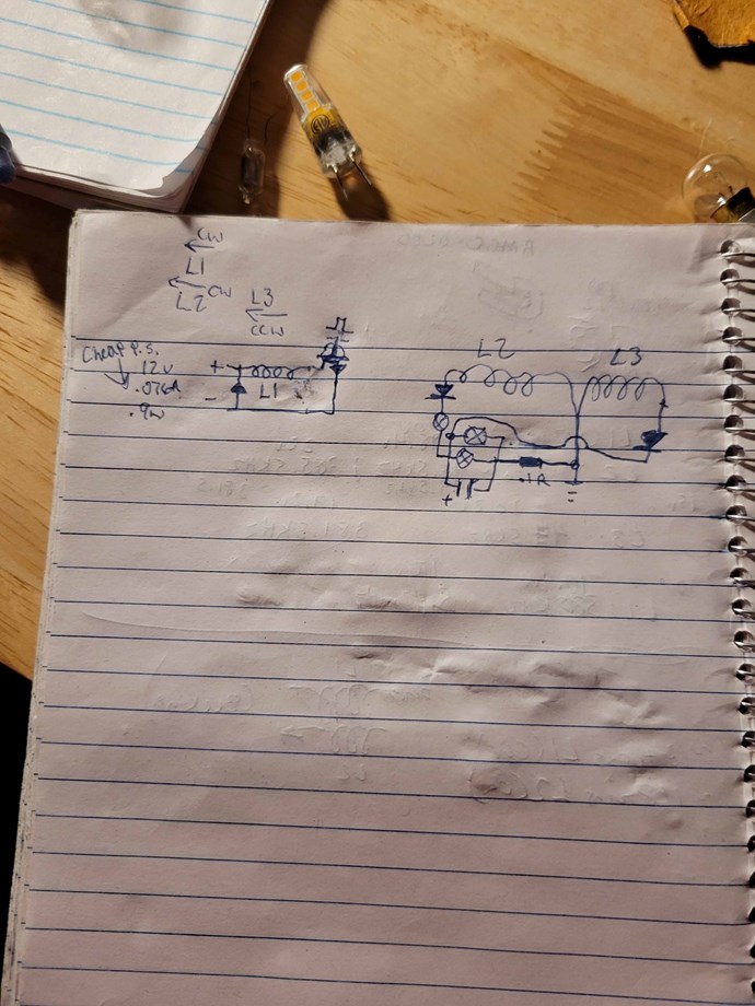
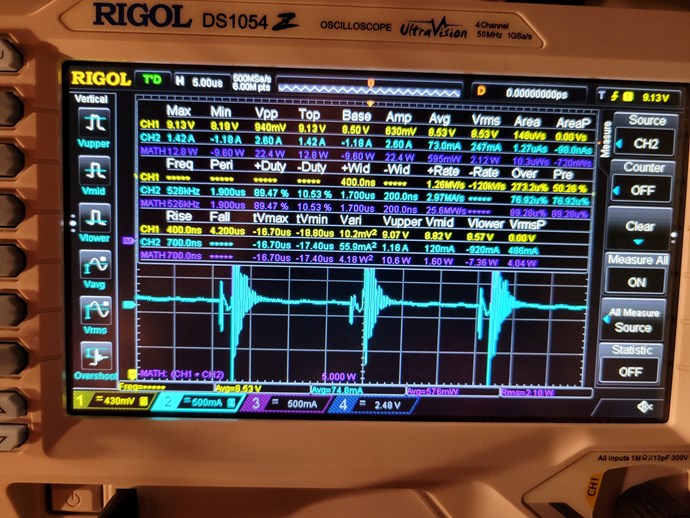
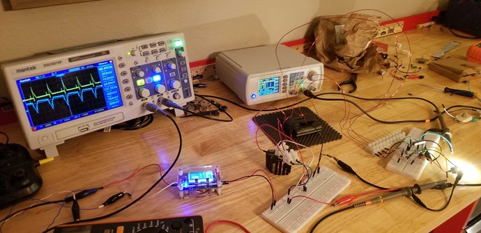
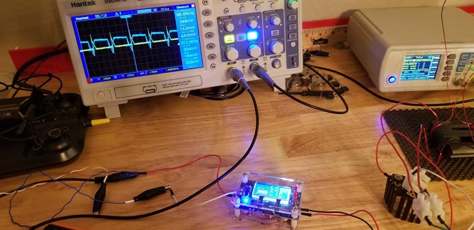
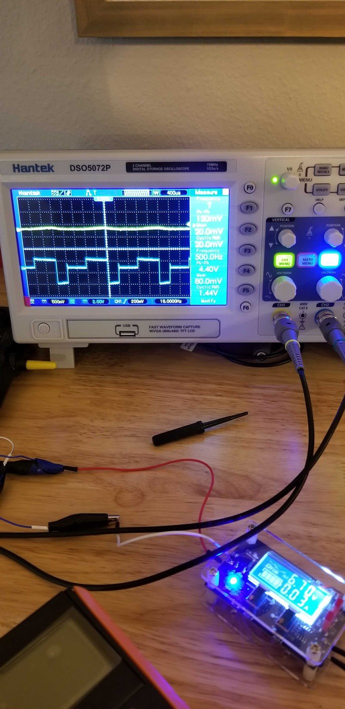
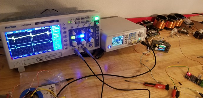
 The following pics are at 3.2khz with 6% duty cycle. The last picture, while slowly sweeping frequency, I hear a small click and my scope went haywire, but still got sawtooth forms in there haha. Unfortunately I didnt have time to change or add loads, but I know theres room for improvement, figured I'd try thicker primary, step voltage up, add load to L3 etc.