My Friends,
Today, I want to go through, and explain how to setup the Mega Wemos WiFi Arduino Clone for a Web Server. Yes, I have done this before, some time ago: Here.
Recently I built a Small Incubator with My Kids, we want to raise our Chickens and Ducks in the Incubator because the Mums are not very dedicated to their Eggs, and they wanted to help, of course I had to make it complicated, and they quickly lost interest, but are very much enjoying seeing the progress!
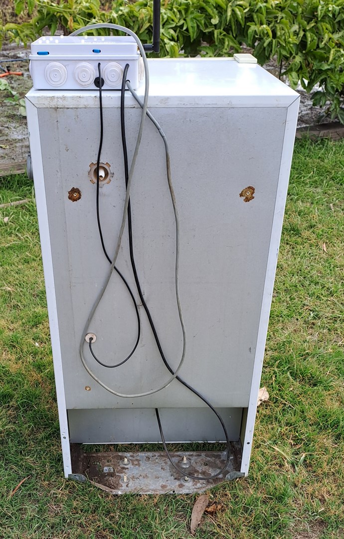
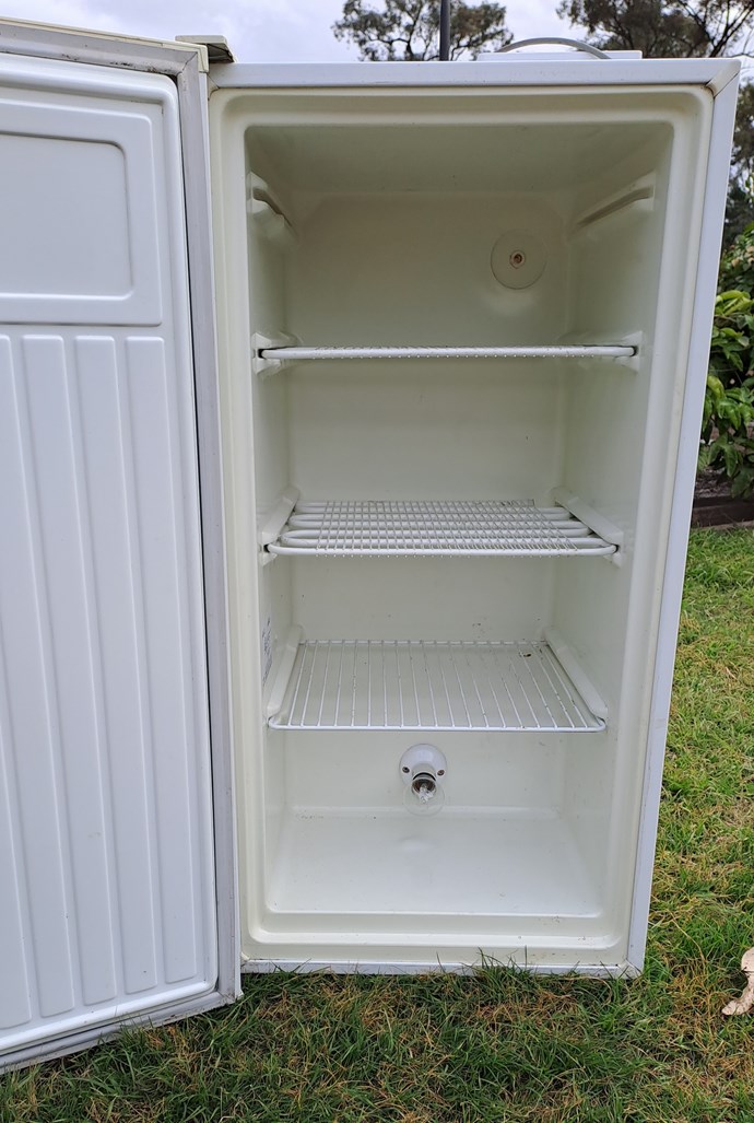
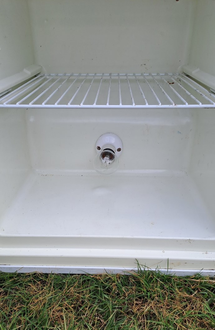
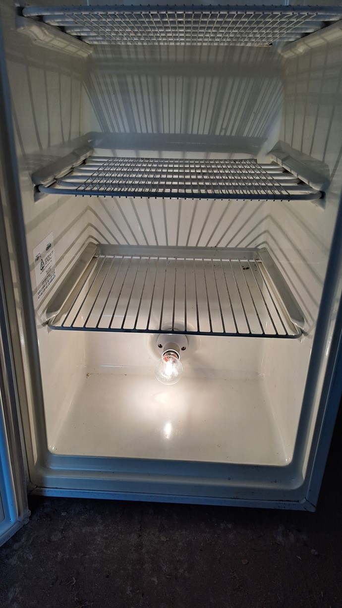
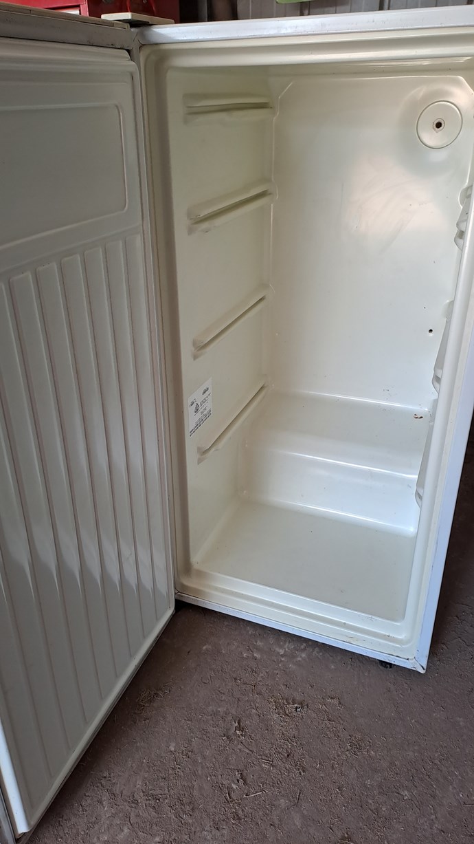
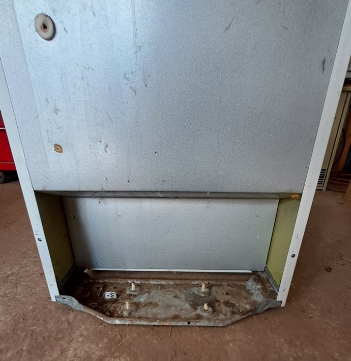
We are Re-Purposing a small Freezer, one that was still working, but was giving us a few problems, so re retired it, Stripped it out and cleaned it up a little:
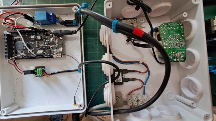
The Shelves have been cleaned up and will go back in. We will have an Incandescent Light Bulb as a Heating Element, and a Temperature Sensor, controlling a small Relay:
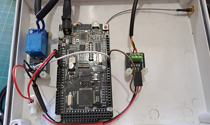
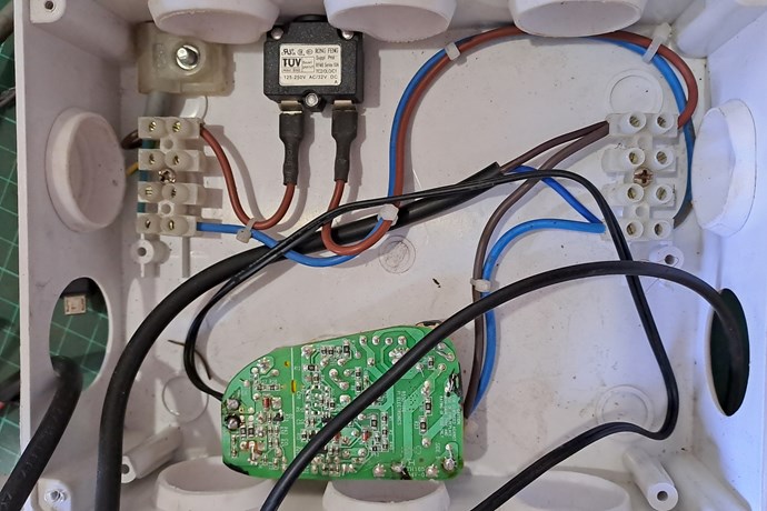
All this, the completed Controller Box will go in where the Compressor used to be, after a clean up:
The Arduino Clone, Mega Wemos:
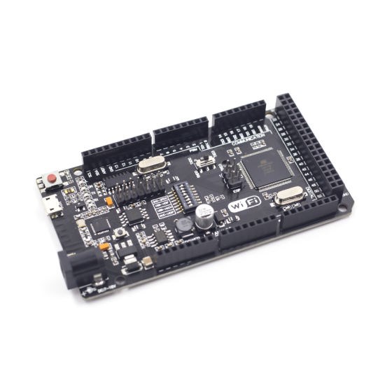
Is a fantastic Board, but it is a bit finicky to get going, 100% It takes some time, and some knowledge to figure out some of the problems associated with it.
Approach
There are several ways we can approach this subject:
- Use the ESP8622 as its own Web Server - Runs its own Web Server Code.
- Run the Code from the Mega 2560 as a By-Pass Web Server.
We will test the second option, run a Web Server as a By-Pass Web Server on the Mega 2560, and see how we go. The First option will be next.
Step 1 - Update the Firmware
Its up to you, you can skip this step and move to step 2, and see if you have any problems? Try it and see!
![]() AI Thinker is the Company that has put this Configuration together and made it available for use, Thanks AI Thinker.
AI Thinker is the Company that has put this Configuration together and made it available for use, Thanks AI Thinker.
FYI: See the NodeMCU Website for a very good tutorial on Firmware Updates.
First, you need to update the Firmware! The Firmware you need to update, is for the ESP8266 WiFi Chip on board.
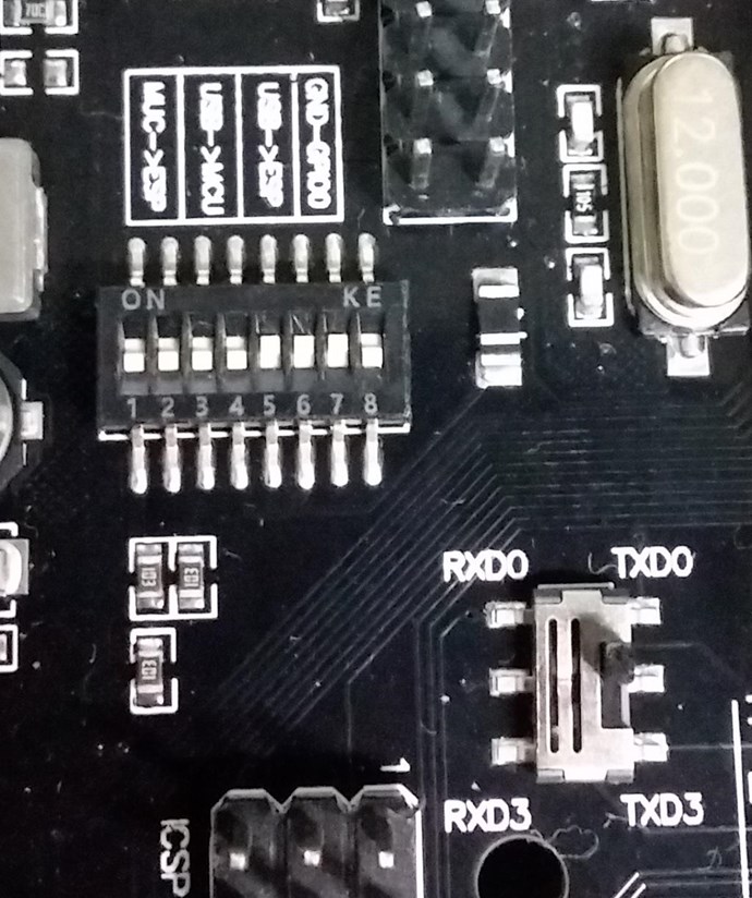
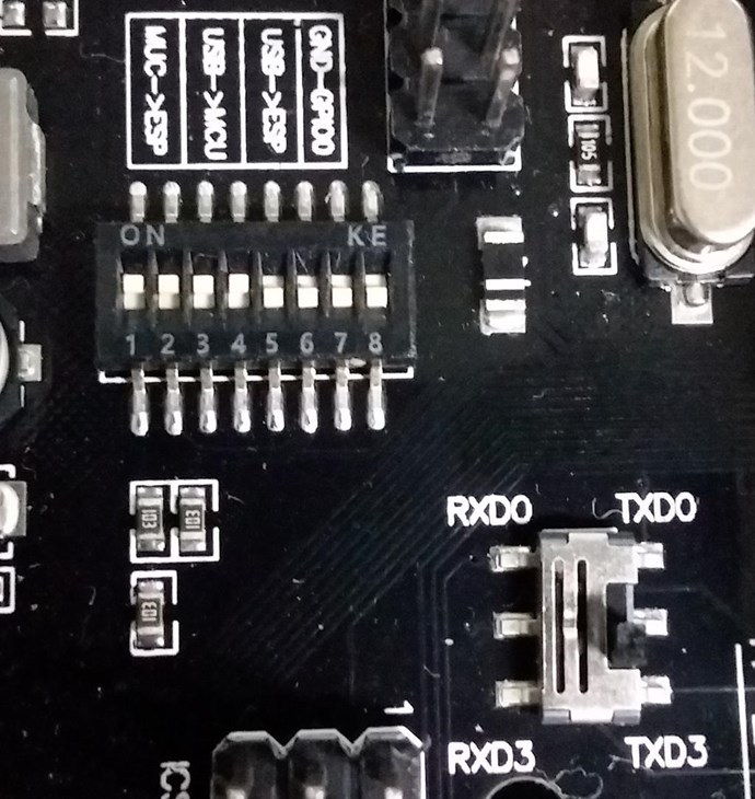
To do this, your "Mega +WiFi R3 Module ATmega2560+ESP8266 32Mb Memory USB-TTL CH340G Mega NodeMCU ESP8266" board, needs to have the Jumper buttons set:
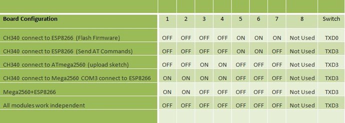
Switch your Jumper Buttons, and the RX/TX Switch, to:
Luckily this is very easy, the best method I found was following this video:
Firmware Download:
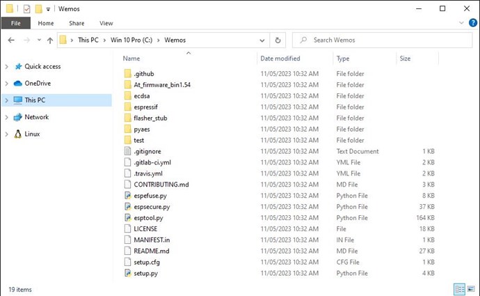
- Firmware and ESPTool Firmware is inside the "At_firmware_bin1.54" directory.
Extract all your Zip Contents to: 'C:\Wemos\' like this:
Install Python 3.0 or above onto your PC if it is not already. Here is the Python Download Link.
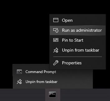
Open a Command Prompt as Administrator, Elevated Permissions:
- Right Click the Command Prompt.
- Go to Run as Administrator.
- Click Yes.
At the Command Prompt, type in: cd C:\Wemos\
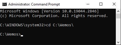
As you can see, this changes the Directory to C:\Wemos\
From the Command Prompt, type in:
python esptool.py --port <YOURCOMPORT> write_flash 0x0000 "At_firmware_bin1.54\AiThinker_ESP8266_DIO_32M_32M_20160615_V1.5.4.bin"
Where your Com Port may be com11:
python esptool.py --port com11 write_flash 0x0000 "At_firmware_bin1.54\AiThinker_ESP8266_DIO_32M_32M_20160615_V1.5.4.bin"
Of course, you need to check what Com Port your "Mega +WiFi R3 Module ATmega2560+ESP8266 32Mb Memory USB-TTL CH340G Mega NodeMCU ESP8266" board is connected on, and replace with your Com Port!
If you get an error:
ModuleNotFoundError: No module named 'serial'
Them just run:
C:\Wemos>pip install pyserial
And then try again.
You should see:
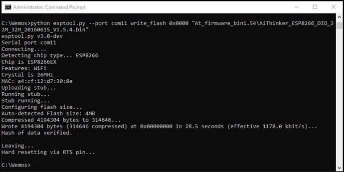
NOTE: On some boards, you may have to do this step several times, I have had one board, that just would not take the Update! Even though it said it was successful! Test and if your WiFi does not work, ESP Not Initialised, repeat this step.
Step 2
When you're done, finished the firmware Flash, set your Jumper Switches back to: "CH340 connect to Mega2560 COM3 connect to ESP8266" mode, so you can use the ATMega and the ESP8266 like a normal Arduino.
After you have this done, plug in your Mega and upload the following Code:
///////////////////////////////////////////////////////////////////////////////////////////////////////////////////////////////////////
// Header: //
//////////////////////////////////////// //
// Includes: // //
#include <Wire.h> // I2C Protocol... //
#include "WiFiEsp.h" // ESP8266 WiFi Library... //
#include <OneWire.h> // OneWire Library DS18B20 Dallas Temperature Sensor... //
#include <DallasTemperature.h> // DS18B20 Dallas Temperature Sensor Library... //
///////////////////////////////////////////////////////////////////////////////////////////////////////////////////////////////////////
///////////////////////////////////////////////////////////////////////////////////////////////////////////////////////////////////////
// WiFi Esp Client: //
//////////////////////////////////////// //
// Initialize WiFi Client: // //
WiFiEspClient client; // A Client that makes a Connection. //
// //
WiFiEspServer server(80); // Init the WiFi Web Server on Port 80. //
// //
int status = WL_IDLE_STATUS; // The Wifi radio's status //
// //
// WiFi Credentials: // //
char ssid[] = "YourSSID"; // Your Network SSID (name) //
char pass[] = "YourPassword"; // Your Network Password //
// //
///////////////////////////////////////////////////////////////////////////////////////////////////////////////////////////////////////
///////////////////////////////////////////////////////////////////////////////////////////////////////////////////////////////////////
// WiFi Esp Client: //
//////////////////////////////////////// //
IPAddress LocalIP(192,168,1,15); // Set the Local Static IP Address. //
IPAddress Gateway(192,168,1,1); // Set the Local Static IP Address. //
IPAddress Subnet(255,255,255,0); // Set the Local Static IP Address. //
IPAddress PrimaryDNS(192,168,1,1); // Set the Local Static IP Address. //
IPAddress SecondaryDNS(192,168,1,1); // Set the Local Static IP Address. //
///////////////////////////////////////////////////////////////////////////////////////////////////////////////////////////////////////
///////////////////////////////////////////////////////////////////////////////////////////////////////////////////////////////////////
// DallasTemperature Temperature Init: //
//////////////////////////////////////// //
// Temperature Sensor Init: // //
bool Reading = false; // Reading Sensor Boolean. //
int SensorPin = 10; // The Temprature Sensor Pin. //
OneWire wire(SensorPin); // One Wire Reference, set the pin to your Digital Pin. //
DallasTemperature DS18B20(&wire); // The DS18B20 DallasTemperature Sensor Reference... //
///////////////////////////////////////////////////////////////////////////////////////////////////////////////////////////////////////
///////////////////////////////////////////////////////////////////////////////////////////////////////////////////////////////////////
// Relay Control Init: //
//////////////////////////////////////// //
// Temperature Sensor Init: // //
int RelayPin = 12; // The Temprature Sensor Pin. //
///////////////////////////////////////////////////////////////////////////////////////////////////////////////////////////////////////
///////////////////////////////////////////////////////////////////////////////////////////////////////////////////////////////////////
// The optimum incubation temperature of wild fowl eggs is within a wide range of values, varying from 33ºC to 39ºC, //
// whereas a narrower range (37ºC to 38ºC) is considered as optimum for domestic poultry (Visschedijk, 1991). //
//////////////////////////////////////// //
float Celsius = 0; // Current Temp. //
float TMin = 37.0; // Min Temp. //
float TMax = 38.0; // Max Temp. //
// Normal ale fermentation temperatures range from 68 to 72 °F (20 to 22 °C) and lager fermentation temperatures from 45 to //
// 55 °F (7 to 13 °C). Also keep in mind that the heat generated by an active fermentation can warm a typical 5-gallon (19-L) //
// batch of beer by 10 to 15 degrees Fahrenheit (5.5 to 8.3 degrees Celsius). //
///////////////////////////////////////////////////////////////////////////////////////////////////////////////////////////////////////
///////////////////////////////////////////////////////////////////////////////////////////////////////////////////////////////////////
// The Server Response Header: //
////////////////////////////////////////////////// //
const String Header = "HTTP/1.1 200 OK\r\n" // //
"Content-Type: text/html\r\n" // //
"Connection: close\r\n" // the connection will be closed after completion of the response //
"Refresh: 30\r\n" // refresh the page automatically every 30 sec //
"\r\n"; // //
///////////////////////////////////////////////////////////////////////////////////////////////////////////////////////////////////////
///////////////////////////////////////////////////////////////////////////////////////////////////////////////////////////////////////
// Home Page Template Init: //
/////////////////////////////////////////////////////////////////////////////////////// //
const String HomePageTemplate = // //
"<!DOCTYPE HTML>\r\n" // //
"<html>\r\n" // //
"<head>\r\n" // //
"<style>body " // //
"{ background-color: linen; } " // //
"h1 " // //
"{ color: maroon; margin-left: 40px; }" // //
"p { color: green; margin: 0px; padding-top: 3px; margin-left: 10px; } " // //
" </style>\r\n" // //
"</head>\r\n" // //
"<body>\r\n" // //
"<h1>Our Home Built Incubator!</h1>\r\n" // //
"<p>Welcome to our home built Incubator's webpage!</p>\r\n" // //
"<br>\r\n" // //
"<p>Incubator Temperature: " // //
"<b>%Celsius%</b>" // //
"℃</p><br>\r\n" // //
"<p>Light is: " // //
"<b>%PinState%</b></p>" // //
"<br>\r\n" // //
"</body>\r\n" // //
"</html>\r\n"; // //
///////////////////////////////////////////////////////////////////////////////////////////////////////////////////////////////////////
///////////////////////////////////////////////////////////////////////////////////////////////////////////////////////////////////////
// Setup the Board: //
///////////////////////////////////////////////////////////////////////////////////////////////////////////////////////////////////////
void setup() {
// Sets the digital pin 10 as output
// pinMode(SensorPin, OUTPUT);
// Sets the digital pin 12 as output
pinMode(RelayPin, OUTPUT);
// Initialize Debugging Serial:
Serial.begin(115200);
// Initialize serial for ESP module: COM3 = Srial3
Serial3.begin(115200);
// Initialize ESP8266 Module:
WiFi.init(&Serial3);
// Initialize DS18B20 DallasTemperature Sensor:
DS18B20.begin();
// Check ESP8266 Status:
if (WiFi.status() == WL_NO_SHIELD) {
Serial.println("[Mega 2560] WiFi shield not present");
// don't continue
while (true);
}
// Attempt to connect to WiFi network:
while (status != WL_CONNECTED) {
Serial.print("[Mega 2560] Attempting to connect to WPA SSID: ");
Serial.println(ssid);
// Connect to WPA/WPA2 Network:
status = WiFi.begin(ssid, pass);
}
// Start the Web Server on Port: 80
server.begin();
// You're connected:
Serial.println("[Mega 2560] You're connected to the network");
// Print the SSID of the Network:
Serial.print("[Mega 2560] SSID: ");
Serial.println(WiFi.SSID());
// Print your ESP8266 WiFi IP Address:
IPAddress ip = WiFi.localIP();
Serial.print("[Mega 2560] IP Address: ");
Serial.println(ip);
// Print Signal Strength:
long rssi = WiFi.RSSI();
Serial.print("[Mega 2560] Signal strength (RSSI):");
Serial.print(rssi);
Serial.println(" dBm");
}
///////////////////////////////////////////////////////////////////////////////////////////////////////////////////////////////////////
// Board Main Loop: //
///////////////////////////////////////////////////////////////////////////////////////////////////////////////////////////////////////
void loop() {
// Listen for incoming Clients:
client = server.available();
// If we have a Client:
if (client) {
// A http request ends with a blank line:
boolean currentLineIsBlank = true;
// While Connected:
while (client.connected()) {
// If Client Avaliable:
if (client.available()) {
// Read Client Request:
char ClientRequest = client.read();
// Write to the Serial Port:
Serial3.write(ClientRequest);
// Delay to let ESP8266 Read and process the Data:
delay(70);
// If you've gotten to the end of the line (received a newline
// character) and the line is blank, the http request has ended,
// so you can send a reply
if (ClientRequest == '\n' && currentLineIsBlank) {
// Init State Variable:
String PinState = "";
// Get the Pin State:
int state = digitalRead(RelayPin);
// Check Pin State:
if (state == 1)
PinState = "On";
else
PinState = "Off";
// Prepare the Html Document, Home Page:
String HomePage = HomePageTemplate;
HomePage.replace("%Celsius%", String(Celsius));
HomePage.replace("%PinState%", PinState);
// Mega 2560 Send Response:
Serial.println("[Mega 2560] Sending Response");
// Send a standard Http Response Header:
client.print(Header);
// Send the Html Document, Home Page:
client.print(HomePage);
// We are done:
break;
}
if (ClientRequest == '\n') {
// You're starting a new line:
currentLineIsBlank = true;
}
else if (ClientRequest != '\r') {
// You've gotten a character on the current line:
currentLineIsBlank = false;
}
}
}
// Give the Web Browser time to Receive and Process the Data:
delay(100);
// Close the connection:
client.stop();
}
// Read DS18B20 Temperature: Incubator
ReadDS18B20Sensor();
// Regulate Temperature:
if (Celsius < TMax)
digitalWrite(RelayPin, HIGH);
else
digitalWrite(RelayPin, LOW);
// Get the Pin State:
int state = digitalRead(RelayPin);
// Secondary Check Pin State:
if (state == 1 && Celsius > TMax)
digitalWrite(RelayPin, LOW); // Maybe Impliment a Fan to cool down if Over Temp Occurs?
}
///////////////////////////////////////////////////////////////////////////////////////////////////////////////////////////////////////
// Read DS18B20 Dallas Temerature Sensor: //
///////////////////////////////////////////////////////////////////////////////////////////////////////////////////////////////////////
void ReadDS18B20Sensor() {
// Size: 23 x 20mm
// Chip: DS18B20
// Voltage: 3.3V, 5V
// Port: Digital two-way single bus
// Temperature range: -50 ℃ to + 125 ℃
// Applicable sensor: Waterproof DS18B20 temperature sensor
// Port: DAT (18B20 data) VCC (18B20 positive) GND (18B20 negative)
// Suitable platform: and Raspberry Pi
// Get Temperatures:
DS18B20.requestTemperatures();
// Get Celsius:
Celsius = DS18B20.getTempCByIndex(0);
// Get Fahrenheit:
float Fahrenheit = DS18B20.toFahrenheit(Celsius);
// We use the function ByIndex, and as an example get the temperature from the first sensor only: for the device 1 (index 0) is
//Serial.print("Temperature: ");
//Serial.print(Celsius);
//Serial.println("C");
}
Your Arduino IDE Should give you a message in the Serail Monitor:
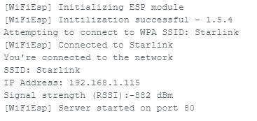
Of course, your details will be different, your IP Address and SSID will be different! No doubt.
Step 3
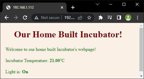
After a Reboot, and a little bit of Patience, you will get a Web Page:
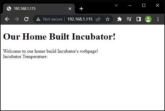
And of course, when I connect the Sensor:
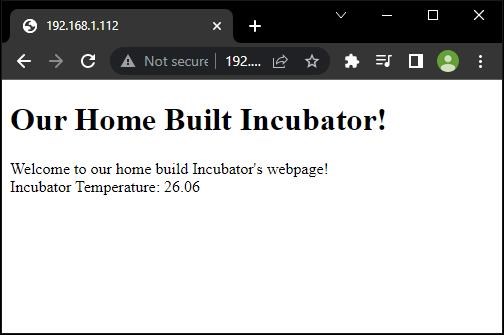
Of course, this is a very simple start to our project, and more can be done to make this more stable, and much more exciting to use, setting a Fixed IP Address would be a start, maybe adding a camera to the inside of the Incubator at a later stage, to see any chicks hatch may be fun!
Come Spring, 1st of September, I hope we might have some Baby Chicks.
Best Wishes,
Chris