Chris
posted this
06 December 2022
- Last edited 06 December 2022
Hey BMW,
All very good questions!
First Question:
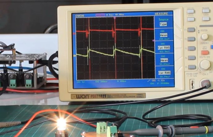
what is this ring down im seeing and why does it go through my diodes like they weren't there, the bottom picture shows that half the wave below midpoint, its gone through two diodes to create that reverse current, How?
Diodes have a specific operating condition, the conduction of the diode is controlled by Voltage right?
If one has a Positive Voltage, but a Negative Current, then the Diode will Conduct at it's Operating Condition, but the Power the Diode "see's" is different. So, under specific conditions, the Diode will conduct, but the Power is different, so it appears unusual.
Second:
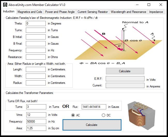
If i measure the inductance of the two output coils in series i get zero uH, so the frequency would be very high! higher than im seeing here in the ring on the top picture, are these waves in the core material?
We covered the Inductance issue in the Thread: Non-Linear Inductance
The Inductance of any Coil is defined by the amount of Current that can Flow in the Coil:
L = ε / di / dt
My opinion, Inductance is a very badly understood subject in general, across the board. Even experienced Electrical Engineers do not understand Inductance very well. They may be able to do all the math, but if they are asked the hard questions, like we see every day in these machines, they are totally lost!
In any Energy Machine, we want, ideally, the Lowest Possible Inductance, this allows for a much greater Volume of Current to Flow! In any "Generator" we see the Inductance drop, with Current Draw!
No one ever covers the fact that Magnetic Effects vary on the Square of the Current. This means, if the Current changes, then the Inductance must have also changed! This is why we see Inductance Meters operate at a specific Frequency mostly!
Floyd Sweet said:
These measurements indicate that field intensity is directly proportional to the square of the current required by the load placed on the device. This is due to its proportional relationship with the virtual value of the magnetic field which theory states is proportional to the current.
This means, the Energy Density of the Magnetic Field is:
Energy Density = uB = B2 / 2μ
The Energy Stored in a Magnetic Field is E = 1/2 LI2
However, Floyd Sweet is saying that the Magnetic Field Strength H, is proportional to the Current Squared, I2, for a given Inductance, which is the same as saying: H = L / I2. Now do we see this theory anywhere? No, its a very illusive and mostly ignored subject! Theory says L = N ΦB / I. We see a hint of this in the Ohms Law equations for AC:
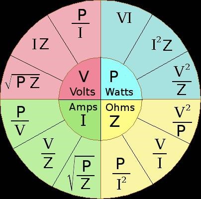
In this diagram, we see: Power P = Current I2 x Impedance Z. With some creative math, we no doubt will see some more direct relationships! If anyone wants to step in and point these equations out?
The unit of Magnetic Field Strength ( H ) is A / m or Amperes per meter. Another equation is: H = I / 2 π raverage. Thus the Radius r, becomes another factor for the Field Strength H.
Sorry for this Rant, its mostly not relevant!
Best Wishes,
Chris